Subscribe to Our Youtube Channel
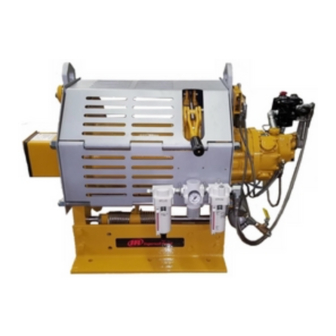
Summary of Contents for Ingersoll-Rand FORCE 5i Man Rider FA150KGi
- Page 1 Product Information ® Model FA150KGi Save These Instructions Form MHD56470 Edition 4 January 2011 45925013 2011 Ingersoll-Rand Company ©...
-
Page 2: Product Description
Only allow trained technicians to perform maintenance on this product. For additional information contact factory or nearest Ingersoll Rand Ingersoll Rand Distributor. For additional supporting documentation refer to Table 1 ‘Product Information Manuals’ on page 2. Manuals can be downloaded from www.ingersollrandproducts.com. The use of other than genuine Ingersoll Rand replacement parts may result in safety hazards, decreased performance and increased maintenance and will invalidate all warranties. -
Page 3: Specifications
SPECIFICATIONS Model Code Explanation Example: FA150KGiMR12A1-CE 150KGi Series: = Force 5 Infinity Air Powered Capacity: 150KGi = 330 lbs (150 kg) Man Rider Rating Designation: = Man Rider Drum Length: = 12 inch (305 mm) standard Brakes: = Automatic drum band brake and disc brake Controls: = Winch mounted lever throttle (standard) Design Temperature:... -
Page 4: Capacity Information
Wire Rope Storage Capacity ** Line Speed @ 150 kg (330 lb) Load Minimum Load for Emergency Lowering Layer 12 inch (305 mm) Drum 26.5 27.7 28.3 28.6 8 (1) ** Wire rope storage capacity based on DNV and NMD standards of 2.5 times wire rope diameter below drum flange. Wire rope storage capacities listed may vary from figures stated elsewhere. -
Page 5: Air Supply
When considering wire rope requirements the actual working load must include not Air line lubricator should be replenished daily and set to provide 6 to 9 drops per only the static or dead load but also loads resulting from acceleration, retardation minute of ISO VG 32 (SAE 10W) oil. -
Page 6: Operation
4. Check Limit Switch operation. Refer to “OPERATION” section on page 6. n Initial Winch Operating Checks For winches that have been in storage the following start-up procedures are required. Winches are tested for proper operation prior to leaving the factory. Before the winch 1. -
Page 7: Winch Motor
Adjustments to cylinder clevis can be made to compensate for normal brake lining wear. The drum brake must be kept properly adjusted to hold the required load. Refer n Emergency Lowering to ‘Adjustments’ in the “MAINTENANCE” section of Product Maintenance Information Manual. -
Page 8: Frequent Inspection
WARNING CAUTION • The line used to pull down the Man Riding device must be attached in such • Any additional weight should be sent in small, easily handled bundles and a manner as to NOT pull on the suspended person or tip the Man Riding device. only enough to cause person to lower. - Page 9 n Winches Not in Regular Use n Storing The Winch 1. Equipment which has been idle for a period of one month or more, but less than 1. Always store the winch in a no load condition. six months, shall be given an inspection conforming to the requirements of 2.
-
Page 10: Air Line Lubricator
3. Add oil slowly until oil is level with level plug port. NOTICE 4. Install level plug. • Always drain oil into a suitable container and inspect drained oil for evidence of damage, metal shavings, dirt, water, etc. Dispose of oil in an n Air Line Lubricator environmentally safe manner. - Page 11 PRODUCT INFORMATION GRAPHICS Main Air Supply Rotate handle to use in normal condition Drum Emergency Lowering Inlet (Dwg. MHP2288) (Dwg. MHP3143) Air Out Regulator 0° 30° Air In Adjust slack arm prior to use, for wire rope take-off angle. Lubricator Filter (Dwg.
- Page 12 PRODUCT INFORMATION GRAPHICS (CONTINUED) Auto Band Brake Auto Cylinder Disc Brake Cylinder Winch Control Emergency Valve Brake Torque Release Emergency Winch Motor Limiter Valve Optional Emergency Brake Valve Lowering System Release Air Source Relief Valve Payout Haul-in Slack Line 125 psi Drain Haul-in Payout...
- Page 13 PRODUCT INFORMATION GRAPHICS (CONTINUED) Push Button to Release Brake Lift Slider Handle UP to Unlock Payout Haul-in Remove Plug and Connect Auxiliary Air to Port 1/4” NPT (Dwg. MHP2289) (Dwg. MHP2976) Fill Plug Reduction Gear Drum Position Assembly Disengage slowly Inboard Upright Install release...
-
Page 14: Service Notes
SERVICE NOTES Form MHD56470 Edition 4... - Page 15 DECLARATION OF CONFORMITY (CS) PROHLÁŠENÍ O SHODĚ (DA) OVERENSSTEMMELSESERKLÆRING (DE) KONFORMITÄTSERKLÄRUNG (EL) ∆ΗΛΩΣΗ ΑΝΑΓΝΩΡΙΣΗΣ (ES) DECLARACIÓN (HU) MEGFELELŐSÉGI NYILATKOZAT DE CONFORMIDAD (FI) VAKUUTUS NORMIEN TÄYTTÄMISESTÄ (FR) CERTIFICAT DE CONFORMITÉ (IT) DICHIARAZIONE DI CONFORMITÀ (LT) ATBILSTĪBAS DEKLARĀCIJA (LV) ATITIKTIES DEKLARACIJA (NL) SCHRIFTELIJKE VERKLARING VAN CONFORMITEIT (NO) KONFORMITETSERKLÆRING (PT) DECLARAÇÃO DE CONFORMIDADE (PL) DEKLARACJA ZGODNOŚCI (SK) PREHLÁSENIE O ZHODE (SL) IZJAVA O SKLADNOSTI...
- Page 16 www.ingersollrandproducts.com...


Need help?
Do you have a question about the FORCE 5i Man Rider FA150KGi and is the answer not in the manual?
Questions and answers