
Related Manuals for Ingersoll-Rand Rider MR150K Series


Summary of Contents for Ingersoll-Rand Rider MR150K Series
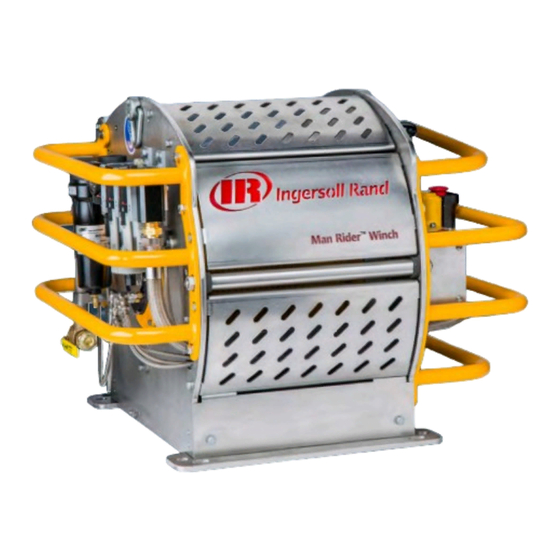
- Page 1 Air Powered Man Rider™Winch MR150K Series Product Information Save These Instructions Form MHD56490 Edition K November 2021 CCN 45957115...
- Page 2 Only allow Ingersoll Rand trained technicians to perform maintenance on this product. For additional information contact Ingersoll Rand factory or nearest Distributor. For additional supporting documentation refer to Table 1, p. Manuals can be downloaded from www.irmhdocs.skysite.com The use of other than genuine Ingersoll Rand replacement parts may result in safety hazards, decreased performance and increased maintenance and will invalidate all warranties.
-
Page 3: Table Of Contents
Table of Contents Product Description and Intended Use ............5 Description and Intended Use . - Page 4 Table of Contents Storing the Winch ................17 Inspection .
-
Page 5: Product Description And Intended Use
Product Description and Intended Use Description and Intended Use This product is an air power-driven winch that has a gear motor. The winches intended use is only for lifting a person (Man Rider™) in a lifting harness and shall not be used for any other purpose. The design life of the winch is based on the environment and amount of use. -
Page 6: Specifications
Specifications Model Code Explanation Example: MR150KA-1CE-B 150K = Man Rider = Capacity 150 kg / 330 lbs 150K = Air Power Source = Lever Throttle Control = Remote Pilot Pendent (xx hose in m) Certification: = Standard (European Standards) = CE and ABS Certified = CE and DNV Certified Options (Other): = Manual Wire Rope Guide... -
Page 7: Capacity Information
S S p p e e c c i i f f i i c c a a t t i i o o n n s s Table 3. Minimum and Maximum Wire Rope Size Cumulative Wire Rope Capacity Drum Barrel Wire Rope Length... -
Page 8: Installation
Installation Prior to installing the product, carefully inspect it for possible shipping damage. Products are supplied fully lubricated from the factory. Check oil levels and adjust as necessary before operating product. Refer to “Lubrication,” p. 24 for recommended oils and lubrication intervals. W W A A R R N N I I N N G G Product not installed properly may fall or cause a load to fall resulting in sever injury or death. -
Page 9: Air Supply
I I n n s s t t a a l l l l a a t t i i o o n n Table 5. Winch Foundation Bolt Forces (Calculated for 1st layer stall load) Vertical Wire Rope Entry Force Acting on Bolt Maximum Shear Force at One Foundation Bolt Connection Winch... -
Page 10: Air Line Filter
I I n n s s t t a a l l l l a a t t i i o o n n C C A A U U T T I I O O N N Shut off air supply before filling air line lubricator. Air Line Filter An air line filter is installed as standard on the winch. -
Page 11: Installing Wire Rope
I I n n s s t t a a l l l l a a t t i i o o n n Installing Wire Rope Refer to Figure 7, p. 1. Cut wire rope to length in accordance with wire rope manufacture’s instructions. 2. -
Page 12: Rigging - Harness (Riding Belt)
I I n n s s t t a a l l l l a a t t i i o o n n Rigging – Harness (riding belt) N N O O T T I I C C E E Harnesses shall be selected in accordance with local or other regulations. -
Page 13: Motor
I I n n s s t t a a l l l l a a t t i i o o n n 4. Hold cam adjustment screw in position and tighten screw. Do not over tighten. 5. Reset the control valve to allow air supply to flow back into the motor. Refer to “Emergency Stop and Reset,”... -
Page 14: Operation
Operation It is recommended that the user and owner check all appropriate and applicable regulations before placing this product into use. Refer to Product Safety Information Manual before operating product. The four most important aspects of product operation are: 1. Follow all safety instructions when operating the product. 2. -
Page 15: Training
O O p p e e r r a a t t i i o o n n Training Program The employer shall provide and implement a training program for all supervisors and employees engaged in the operation of raising, lowering or suspending personnel using proper suspension devises from a winch load line so that they are familiar with the requirements of the hoisting system and are able to recognize the associated hazards and take appropriate measures. -
Page 16: Overload Device
O O p p e e r r a a t t i i o o n n Overload Device W W A A R R N N I I N N G G This overload protection device is factory set at 125% maximum of the SWL at rated layer. Refer Specifications, p. -
Page 17: Alternate Lifting/Lowering
O O p p e e r r a a t t i i o o n n N N O O T T I I C C E E After each use of the emergency lowering device, reset the Emergency Stop Valve and verify the main air supply is in proper working condition and able to fulfill its task. -
Page 18: Inspection
Inspection Inspection information is based in part on American Society of Mechanical Engineers Safety Codes (ASME B30.7). W W A A R R N N I I N N G G All new or repaired equipment should be inspected and tested by Ingersoll Rand trained Technicians to ensure safe operation at rated specifications before placing equipment in service. -
Page 19: Maintenance Interval Chart
I I n n s s p p e e c c t t i i o o n n Maintenance Interval Chart Refer to Table 9, p. 19 for recommended maintenance schedule. N N O O T T I I C C E E Winch Load Test! Do an annual winch load test for all applications. -
Page 20: Daily Inspection
I I n n s s p p e e c c t t i i o o n n Daily Inspection Complete inspections prior to start of daily tasks. Conduct visual inspections during regular operation for indications of damage or evidence of malfunction (such as abnormal noises). 1. -
Page 21: Quarterly Inspection
I I n n s s p p e e c c t t i i o o n n Quarterly Inspection Complete a ‘Quarterly Inspection’ on a recurring basis to provide regular winch monitoring. In addition to the requirements of ‘Daily Inspection’ also inspect the following: 1. -
Page 22: Inspection Report
Inspection Report Make a photo copy of this form and use as an inspection record. Ingersoll Rand MR150K Series Air Winches Model Number: Date: Serial Number: Inspected by: Reason for Inspection: (Check Applicable Box) Scheduled Periodic Inspection: (_____ Months _____ Years) Operating Environment: Discrepancy(s) noted during Frequent Inspection Normal ____ Heavy____ Severe ____... -
Page 23: Adjustments
Adjustments Overload Device W W A A R R N N I I N N G G Overload is factory set and sealed with red paint and should not be adjusted without consulting an Ingersoll Rand trained technician. Figure 2. MHP2683 Securing Screw Adjustment... -
Page 24: Lubrication
Lubrication To ensure continued satisfactory operation of winch, all points requiring lubrication must be serviced with correct lubricant at proper time intervals as indicated for each assembly. Use only those lubricants may affect product performance. Approval for use of other lubricants must be obtained from your Ingersoll Rand distributor. -
Page 25: General Lubrication
L L u u b b r r i i c c a a t t i i o o n n General Lubrication W W A A R R N N I I N N G G Pneumatic Winches use oil to prevent excessive heat build up and to prevent wear that could cause sparks. -
Page 26: Product Information Graphics
Product Information Graphics Figure 4. MHP3378 10° -20° -5° -5° 10° 30° -20° -60° -60° -100° Roller and Weight S ta rting Rop e End ing Rop e Ang le (de gree ) Ang le (de gree ) Positions -- - -- - - 20 -- -... - Page 27 P P r r o o d d u u c c t t I I n n f f o o r r m m a a t t i i o o n n G G r r a a p p h h i i c c s s Figure 5.
- Page 28 P P r r o o d d u u c c t t I I n n f f o o r r m m a a t t i i o o n n G G r r a a p p h h i i c c s s Figure 8.
- Page 29 P P r r o o d d u u c c t t I I n n f f o o r r m m a a t t i i o o n n G G r r a a p p h h i i c c s s Figure 12.
-
Page 30: Air Schematics (For Mk2 Before 11/19/2021)
Air Schematics (For MK2 before 11/19/2021) MHD56490... -
Page 31: Air Schematics (For Mk3 After 11/19/2021)
Air Schematics (For MK3 after 11/19/2021) MHD56490... -
Page 32: Torque Chart
Torque Chart Standard Coarse Thread Torque SAE Grade 5 SAE Grade 8 Size Lubricated PTFE Lubricated PTFE 1/4-20 8-10 12-14 9-10 5/16-18 17-20 13-15 25-28 18-21 11-13 3/8-16 31-35 23-26 14-16 44-49 33-37 20-22 7/16-14 49-56 37-42 22-25 70-79 52-59 31-36 1/2-13 75-85... - Page 33 T T o o r r q q u u e e C C h h a a r r t t Metric Fine Thread Torque Class 8.8 / 9.8 Class 10.9 Size Lubricated PTFE Lubricated PTFE M8x1 22-25 17-19 10-11 28-32 21-24...
-
Page 34: Warranty
Warranty Ingersoll Rand Limited Warranty Ingersoll Rand Company (“IR”) warrants to the original user its material handling products (“Products”) to be free of defects in material and workmanship for a period of one year from the date of purchase. IR will, at its option either (1) repair, without cost, any Product found to be defective, including parts and labor charges, or (2) replace such Products or refund the purchase price, less a reasonable allowance for depreciation, in exchange for the Product. - Page 35 N N o o t t e e s s MHD56490...
- Page 36 i i n n g g e e r r s s o o l l l l r r a a n n d d p p r r o o d d u u c c t t s s . . c c o o m m ©2021 Ingersoll Rand...
Need help?
Do you have a question about the Rider MR150K Series and is the answer not in the manual?
Questions and answers