
Related Manuals for Ingersoll-Rand FORCE 5i Man Rider FA2i-MRA


Summary of Contents for Ingersoll-Rand FORCE 5i Man Rider FA2i-MRA
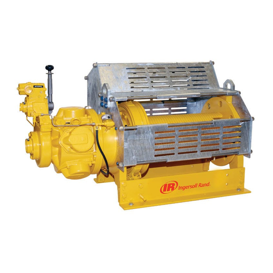
- Page 1 Product Information ® Model FA2i-MRA (ANSI) Man Rider Save These Instructions Form MHD56331 Edition 1 September 2005 71468110 © 2005 Ingersoll-Rand Company...
-
Page 2: Product Description
Parts Information. Manuals can be downloaded from www.winchandhoistsolutions.com The use of other than genuine Ingersoll-Rand replacement parts may result in safety hazards, decreased performance, increased maintenance and may invalidate all warranties. The original language of this manual is English. Refer all communications to the nearest Ingersoll-Rand Office or Distributor. -
Page 3: Specifications
** Remote throttles are provided with 6 feet (2 metres) of hose. Specify hose lengths greater than 10 feet. For lengths greater than 66 ft (20 m) please contact your Ingersoll-Rand distributor or the factory for control acceptability. Metric lengths are provided for reference only, order lengths in feet. -
Page 4: Installation
Table 1: Specifications Air System Minimum Air Air Motor Pipe Drum Drum Flange System Hose Size Net Weight * Air Consumption Inlet Size Barrel Diameter Diameter Model Rated Operating (inside diameter) (at rated pressure and load) Pressure scfm cu.m/min inch inch inch inch... -
Page 5: Electrical Grounding
Table 7: Bolt Hole Dimensions Drum Length Dimension 12 in. (305 mm) 16 in. (406 mm) 24 in. (610 mm) 30 in. (762 mm) 36 in. (914 mm) “A” 9.00* 7.50 10.00 “B” Contact Factory 229* 0.6875 “C” 17.5 Table 8: Winch Foundation Bolt Forces Drum Length Force Acting on Bolt 12 in. -
Page 6: Operation
Mufflers Winch Guard Ensure muffler is installed in winch piped away exhaust manifold and control valve exhaust port. Check mufflers periodically to ensure they are functioning correctly. Use of a winch guard is recommended on all winches. WARNING Motor • Do not allow wire rope to come in contact with winch guard panels during winch operation. - Page 7 Voice communication must be established and maintained between winch NOTICE operator, personnel being lifted and personnel located at each landing (as applicable). • Refer to Product Safety Information Manual for Man Rider Winches Form Winch operators must maintain at least 4 tight wraps of wire rope on the MHD56251 for essential safety information not covered in this manual.
- Page 8 To adjust the limit switch set points, refer to “INSTALLATION” section on page 4. * For distances greater than 66 feet (20 metres) contact Ingersoll-Rand Technical Sales for control suitability.
-
Page 9: Winches Not In Regular Use
• All new, altered or modified equipment should be inspected and tested by covers. Replace worn or damaged parts. Clean, lubricate and reassemble. Ingersoll-Rand trained technicians to ensure safe operation at rated 8. SUPPORTING STRUCTURE (WEEKLY). Check for distortion, wear and continued specifications before placing equipment in service. -
Page 10: General Lubrication
NOTICE wire rope manufacturer. • Do NOT use synthetic lubricants in air motor. Synthetic lubricants will result 2. Apply a wire rope lubricant, Ingersoll-Rand LUBRI-LINK-GREEN® or ISO VG 100 in oil blowing by piston rings. (SAE 30W) oil. 3. Brush, drip or spray lubricant weekly, or more frequently, depending on severity of service. - Page 11 PRODUCT INFORMATION GRAPHICS DRUM (Dwg. MHP0133) (Dwg. MHP2398) Fill Plug Drum Position Reduction Gear Assembly Level Plug Position (Dwg. MHP2686) Inboard Upright (Dwg. MHP0140) (Dwg. MHP0191) Form MHD56331 Edition 1...
- Page 12 PRODUCT INFORMATION GRAPHICS CONTINUED (Dwg. MHP2688) View: Facing Air Motor Counterclockwise Clockwise Direction: Direction: Wire Rope Wire Rope Haul-In Payout (Dwg. MHP1892) 1-1/4 inch 90° Fill Plug With lever at neutral position, fold down to prevent accidental winch operation. (Dwg. MHP0447) Level Plug Drain Plug (Dwg.
- Page 13 PRODUCT INFORMATION GRAPHICS CONTINUED Winch Foundation Bolt Forces Calculated for 1st layer stall load (9,000 lbf) 1st Layer Line Radius - 5.6” Rear Front 14” 20” Total tensile Maximum shear load which force at one is shared boundation bolt by the rear connection foundation bolts (Dwg.
-
Page 14: Service Notes
SERVICE NOTES Form MHD56331 Edition 1... -
Page 15: Declaration Of Conformity
PREHLÁSENIE O ZHODE IZJAVA O SKLADNOSTI (SK) (SL) (SV) FÖRSÄKRAN OM ÖVERENSSTÄMMELSE Ingersoll-Rand 529, Avenue Roger Salengro, 59450 Sin Le Noble, France Declare under our sole responsibility that the product: Pneumatic Winches Prohlašujeme na svou zodpovědnost, že produkt: Pnematické Navijáky (CS) (DA) Erklærer som eneansvarlig, at nedenstående produkt: Pneumatiske spil (DE) Erklären hiermit,... - Page 16 www.winchandhoistsolutions.com...
Need help?
Do you have a question about the FORCE 5i Man Rider FA2i-MRA and is the answer not in the manual?
Questions and answers