
Related Manuals for Shuttle MK35


Summary of Contents for Shuttle MK35
- Page 1 MK35/MK35N Socket A AMD Athlon XP / Duron Processor Based DDR Main Board User's Manual...
- Page 2 WARNING Thermal issue is highly essential for processors with a speed of 600MHz and above. Hence, we recommend you to use the CPU fan qualified by AMD or motherboard manufacturer. Meanwhile, please make sure CPU and fan are securely fastened well. Otherwise, improper fan installation not gets system unstable but also could damage both CPU and motherboard because insufficient thermal dissipation.
- Page 3 MK35/MK35N SocketA AMD Athlon/ Duron Processor based DDR Mainboard Manual Version 1.0 Disclaimer This company shall not be liable for any incidental or consequential damages resulting from the performance or use of this product. This company makes no representations or warranties regarding the contents of this manual.
-
Page 4: Table Of Contents
TABLE OF CONTENTS WHAT'S IN THE MANUAL ..............5 Quick Reference ....................5 About This Manual.................... 5 1 INTRODUCTION ................6 1.1 TO DIFFERENT USERS ................6 First-Time DIY System Builder ..............6 Experienced DIY User ................6 System Integrator ..................6 1.2 ITEM CHECKLIST .................. - Page 5 3.2 JUMPER SETTINGS ................. 23 JUMPER & CONNECTOR GUIDE ............24 Jumpers BIOS Write Protection(JP3) ..............27 Clear COMS (JP1) ................27 CPU Frequency (JP5)................28 Back-Panel Connectors PS/2 Keyboard & PS/2 Mouse Connectors ..........29 COM1 Port Connector ................29 VGA Connector..................
- Page 6 Other Connectors ATX Power Supply Connector (ATX1) ............ 34 Cooling FAN Connectors for CPU (CPUFAN1) and Case (CASFAN1) Fans ................. 34 COM2 Connector (COM2) ..............35 Front-Panel Microphone and Line-Out Header (AUDIO1) ....... 35 Audio CD-IN Connector (CD1) ............... 36 IR Header (IR1) ..................
- Page 7 5 BIOS SETUP ................... 46 5.1 ENTER THE BIOS ..................46 5.2 THE MAIN MENU ..................47 STANDARD CMOS FEATURES ............... 49 ADVANCED BIOS FEATURES ..............53 ADVANCED CHIPSET FEATURES............57 INTEGRATED PERIPHERALS ..............62 POWER MANAGEMENT SETUP .............. 66 PNP/ PCI CONFIGURATION ..............
-
Page 8: What's In The Manual
WHAT'S IN THE MANUAL Quick Reference Hardware Installation >> Step-by-Step ..........Page 11 Jumper Settings >> A Closer Look ............Page23 Software Utility >> How to Install ............Page 38 BIOS Setup >> How to Configure ............Page 46 About This Manual For First-Time DIY System Builder ............ -
Page 9: Introduction
It integrates the most advanced functions you can find to date in a compact Micro ATX mainboard. This manual adopted in MK35 and MK35N mainboards at the same time. The difference between MK35 and MK35N is that MK35N equips with onboard LAN Controller. -
Page 10: Item Checklist
1.2 Item Checklist Check all items with you MK35/MK35N mainboard to make sure nothing is miss- ing. The complete package should include: CA SF AN1 CP UF A N1 DIM 1 DIM 2 CO M2 CO M2 CO M2 ! One piece of MK35/MK35N Mainboard... -
Page 11: Features
2 FEATURES MK35/MK35N mainboard is carefully designed for the demanding PC user who wants high performance and maximum intelligent features in a compact package. 2.1 Specifications - CPU Support Support Socket462 package CPU AMD Athlon Processor with 200/266 MHz FSB... - Page 12 - IO Interface Provides a variety of IO interfaces: Ø 1* Floppy interface for 3.5-inch FDD with 720KB, 1.44MB, or 2.88MB format or for 5.25-inch FDD with 360K or 1.2MB format. Ø 1* PS/2 mouse connector. Ø 1* PS/2 Keyboard connector. Ø...
- Page 13 - System BIOS Provides licensed Award BIOS V6.0 PG on 2Mb Flash EEPROM and supports Green PC, Desktop Management Interface (DMI). - Micro ATX Form Factor System board conforms to the Micor ATX specification. Board dimension: 244mm*230mm. - Advanced Features Ø...
-
Page 14: Hardware Installation
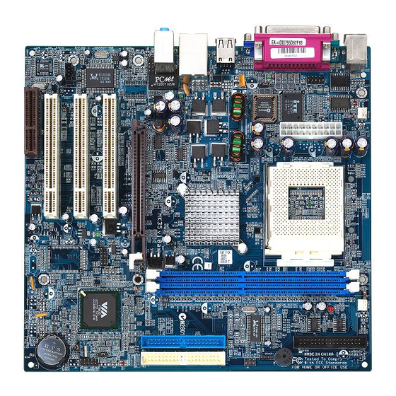
Before removing or installing any of these devices including CPU, DIMMs, Add-On Cards, Cables, please make sure to unplug the onboard power connector. This section outlines how to install and configure your MK35/MK35N mainboard. Refer to the following mainboard layout to help you identify various jumpers, connectors, slots, and ports. -
Page 15: Step 1 Install The Cpu
Step 1 Install the CPU: 1. Locate the CPU ZIF (Zero Insertion Force) socket on the upper-right sector of your mainboard (between the back-panel connectors and the DIMM memory slots). 2. Pull the CPU ZIF socket lever slightly sideways away from the socket to unlock the lever, and then bring it to an upwardly vertical position. -
Page 16: Step 2 Set Jumpers
Step 2. Set Jumpers The default jumper settings have been set for the common usage standard of this mainboard. Therefore, you do not need to reset the jumpers unless you require special adjustments as in any of the following cases: 1. -
Page 17: Step 4 Install Internal Peripherals In System Case
Step 4 Install Internal Peripherals in System Case Before you install and connect the mainboard into your system case, we recommend that you first assemble all the internal peripheral devices into the computer housing, including but not limited to the hard disk drive (IDE HDD), floppy disk drive (FDD), CD-ROM drive, and ATX power supply unit. -
Page 18: Step 5 Mount The Mainboard On The Computer Chassis
Step 5 Mount the Mainboard on the Computer Chassis 1. You may find that there are a lot of different mounting hole positions both on your computer chassis and on the mainboard. To choose a correct mounting hole, the key point is to keep the back-panel of the mainboard in a close fit with your system case, as shown below. -
Page 19: Step 6 Connect Front-Panel Switches/Leds/Speaker/Usb
Step 6 Connect Front-Panel Switches/LEDs/Speaker/USB connectors You can find there are several different cables already existing in the system case and originating from the computer's front-panel devices (HDD LED, Power LED, Reset Switch, PC Speaker, or USB devices etc.) These cables serve to connect the front-panel switches, LEDs, and USB connectors to the mainboard's front-panel connectors group (PANEL1), as shown below. -
Page 20: Step 7 Connect Ide & Floppy Disk Drives
Step 7 Connect IDE & Floppy Disk Drives 1. IDE cable connector IDE1 IDE2 2. FDD cable connector Step 8 Connect Other Internal Peripherals 1. CD1 and Front-Panel AUDIO1 connectors AUDIO1 CD 1 - 17 -... -
Page 21: Step 9 Connect Power Supply
2. IR connector(IR1) Step 9 Connect Power Supply 1. System power connector - 18 -... -
Page 22: Step 10 Install Add-On Cards In Expansion Slots
Step 10 Install Add-on Cards in Expansion Slots 1. AGP Card 2. PCI Card 3. CNR Card Step 11 Connect External Peripherals to Back-Panel You are now ready to put the computer case back together and get on to the external peripherals connections to your system's back-panel. - Page 23 PS/2 Mouse 1. PS/2 Mouse and Keyboard Ports PS/2 keyboard Parallel Port 2. Prallel Port foxconn 3. COM1 Port COM1 Port 4. VGA Port VGA Port 5. USB0 / USB1 Port Connectors USB Port 0 USB Port 1 - 20 -...
- Page 24 6. USB2 / USB3 Port Connectors USB Port 2 USB Port 3 7. LAN Port(MK35N only) LAN Port 8. Line-In Port , Line-out Port and Mic-In Port Line-In Port Line-Out Port Mic-In Port - 21 -...
-
Page 25: Step 12 Install Driver & Software Components
2000/ME/NT operating systems . Make sure your operating system is already installed before running the drivers installation CD-ROM programs. 1. Insert the MK35/MK35N bundled CD-ROM into your CD-ROM drive. The auto-run program will display the drivers main installation window on screen. -
Page 26: Jumper Settings
3.2 Jumper Settings Several hardware settings are made through the use of jumper caps to con- nect jumper pins to the mainboard. Pin #1 could be located at any corner of each jumper; you just find a location marked with a while right angle, which stands for pin1#. -
Page 27: Jumper & Connector Guide
Jumper & Connector Guide Use the mainboard layout on page 11 to locate CPU socket, memory slots, expansion slots, jumpers and connectors on the mainboard during installation. The following list will help you identify jumpers, slots, and connectors along with their assigned functions: B2~B4 B5~B6 B7~B9... - Page 28 Jumpers : BIOS Flash Protect Jumper : Clear CMOS Jumper : CPU Frequency Jumper Back-Panel Connectors PSKBM1 : PS/2 Keyboard PSKBM1 : PS/2 Mouse COM1 : Serial Port 1 Connector(DB9 male) VGA1 : VGA Port (DB15 female) PRINTER : Parallel Port (DB25 female) B5~B6 : 2 USB Ports B7~B8...
- Page 29 Other Connectors: ATX1 : ATX Power Header (20-pin header) CPUFAN1 : CPU Fan Power CASFAN1 : Case Fan Power COM2 : On board Serial port 2 header. E3 E4 E3 E5 Audio 1 : Front-oriented microphone/line-out port header : On board audio Header : IR Header - 26 -...
-
Page 30: Jumpers
Jumpers BIOS Write Protection (JP3) JP3 is used to protect BIOS from abnormal writing. You may choose to place mini jumper on pins 2-3 for BIOS write protection; however, please place mini jumper on pins 1-2 if you need to reflash BIOS. To enable reflashing the BIOS Pin 1-2 (Default) -
Page 31: Cpu Frequency (Jp5)
CPU Frequency (JP5) JP5 is set the CPU frequency (100MHz or 133 MHz) according to the CPU. You may choose to place mini jumper on pins 1-2 for 100MHz; however, please place mini jumper on pins 2-3 if you need to run 133MHz. 100MHz Pin 1-2 133MHz... -
Page 32: Back-Panel Connectors Ps/2 Keyboard & Ps/2 Mouse Connectors
Back-Panel Connectors PS/2 Keyboard & PS/2 Mouse Connectors Two 6-pin female PS/2 keyboard & Mouse connectors are located at the rear panel of the mainboard. PS/2 Mouse Depending on the computer housing you use (desktop or tower), the PS/2 Mouse connector is situated at the top of the PS/2 Keyboard connector when the mainboard is laid into a desktop, as opposed to a tower where the PS/2... -
Page 33: Line-Out
USB Port 2 USB Port Connectors B7~B8 This mainboard offers USB port. Plug each USB device jack into an available USB2/ USB3 connectors. USB Port 3 LAN Port Connector(MK35N only) LAN Port This mainboard can accommodate one device on LAN. Attach a 10/100 baseT cable to the RJ45 at the back-panel of your computer. -
Page 34: Front-Panel Connectors
Front-Panel Connectors HDD LED Connector (HD LED) Attach the connector cable from the IDE device LED to the 2-pin HD LED header. The HDD LED lights up whenever an IDE device is active. PANEL1 9 10 Green LED Connector (GRN LED) The Green LED (GRN LED) indicates that the system is currently in one of the power saving mode (Doze//standby/Suspend). -
Page 35: Atx Power On/Off Switch Connector (Power Switch)
ATX Power On/Off Switch Connector (PWRSW) The Power On/ Off Switch is a momentary-type switch used for turning on or off the system's ATX power supply. Attach the connector cable from the Power Switch to the 2-pin Power Switch header on the mainboard. PANEL1 9 10 Speaker Connector (SPEAKER1) -
Page 36: Internal Peripherals Connectors Enhanced Ide Ports And Floppy Connectors
Internal Peripherals Connectors Enhanced IDE Ports and Floppy Connector The MK35/MK35N mainboard features two 40-pin dual-channel IDE device connectors (IDE1/IDE2) providing support to up to four IDE devices, such as CD- ROM and Hard Disk Drives (H.D.D.). This mainboard also includes one 34-pin floppy disk controller to accommodate the Floppy Disk Drive (FDD1). -
Page 37: Other Connectors
Other Connectorrs ATX Power Supply Connector (ATX1) Locate the 20-pin male header ATX power connector (ATX1) on your mainboard. Plug the power cable from the ATX power supply unit directly into (ATX1) ATX power supply connector. Note 1: The ATX power connector is directional and will not go in unless the guides match perfectly making sure that pin#1 is properly positioned. -
Page 38: Com2 Connector (Com2)
COM2 Connector (COM2) This mainboard built in with one 10-pin header for Serial 2 port (COM2). Pin Assignment: 1=DCD 2=RxD 3=TxD 4=DTR COM2 5=GROUND 6=DSR 7=RTS 8=CTS 9=RI 10=KEY Front panel Microphone and Line_out Header (AUDIO1) This header allows the user to install auxiliary front-panel1 microphone and line-out ports for easier access. -
Page 39: Audio Cd-In Connector (Cd1)
Audio CD_IN Connector (CD1) Port CD1 is used to attach an audio connector cable from the CD-ROM drive. CD 1 IR Header (IR1) If you have an Infrared device, this mainboard can implement SIR (Standard IR) transfer function. To enable the IR transfer function, follow these steps: Pins Assignment: 1=NC 2=KEY... -
Page 40: System Memory Configuration
3.3 System Memory Configuration The MK35/MK35N mainboard has two 184-pin DIMM banks that allow you to install from 128MB up to 2GB of system memory. Each 184-pin DIMM (Dual In-line Memory Module) bank can accommodate 128MB, 256MB, 512MB, and 1GB of PC1600/PC2100 compliant 2.5V single or double side 64-bit wide data path DDR SDRAM modules. -
Page 41: Software Utility
4 SOFTWARE UTILITY 4.1 Mainboard CD Overview Note: The CD contents attached in the MK35/MK35N mainboard are subject to change without notice. To start your mainboard CD disc, just insert it into your CD-ROM drive, and the CD AutoRun screen should appear. If the AutoRun screen does not appear, double click or run D:\Autorun.exe (assuming that your CD-ROM... -
Page 42: Install Mainboard Software
If the AutoRun screen does not appear, double click on Autorun icon in My Computer to bring up Mainboard Software Setup screen. Select using your pointing device (e.g. mouse) on the "Install Mainboard MK35 Software"or "Install Mainboard MK35N Software" bar to run into sub-menu. The Mainboard MK35 Software include: [4.2.A] Install VIA Chipset Driver... - Page 43 4.2.A Install VIA Chipset Driver Select using your pointing device (e.g. mouse) on the "Install VIA Chipset Driver" bar to install VIA chipset driver. MK35 MK35N Once you made your selection,a Setup window run the installation automatically. When the copying files is done, make sure you reboot the system to take the installation effect.
- Page 44 4.2.B Install VGA Device Driver Select using your pointing device (e.g. mouse) on the "Install VGA Device Driver" bar to install VGA chipset driver. MK35 MK35N Once you made your selection,a Setup window run the installation automatically. When the copying files is done, make sure you reboot the system to take the installation effect.
- Page 45 4.2.C Install Audio Driver Select using your pointing device (e.g. mouse) on the "Install Audio Driver" bar to install AC'97 Audio driver. MK35 MK35N Once you made your selection,a Setup window run the installation automatically. When the copying files is done, make sure you reboot the system to take the installation effect.
- Page 46 4.2.D Install LAN Driver (MK35N Only) Select using your pointing device (e.g. mouse) on the "Install LAN Driver" bar to install LAN driver. MK35N Once you made your selection,a Setup window run the installation automatically. When the copying files is done, make sure you reboot the system to take the installation effect.
- Page 47 4.2.E Install USB 2.0 Driver Select using your pointing device (e.g. mouse) on the "Install USB 2.0 Driver" bar to install USB 2.0 driver. MK35 MK35N Once you made your selection,a Setup window run the installation automatically. When the copying files is done, make sure you reboot the system to take the installation effect.
-
Page 48: View The User's Manual
Insert the attached CD into your CD-ROM drive, and the CD AutoRun screen should appear. If the AutoRun screen does not appear, double click on Autorun icon in My Computer to bring up Shuttle Mainboard Software Setup screen. Select the item using your pointing device (e.g. mouse) on the "Manual"bar. -
Page 49: Bios Setup
5 BIOS SETUP MK35/MK35N BIOS ROM has a built-in Setup program that allows users to modify the basic system configuration. This information is stored in battery- backed RAM so that it retains the Setup information even if the system power is turned off. -
Page 50: The Main Menu
5.2 The Main Menu Once you enter the AwardBIOS(tm) CMOS Setup Utility, the Main Menu will appear on the screen. The Main Menu allows you to select from several setup functions and two exit choices. Use the arrow keys to select among the items and press <Enter> to accept and enter the sub-menu. - Page 51 Integrated Peripherals Use this menu to specify your settings for integrated peripherals. Power Management Setup Use this menu to specify your settings for power management. PnP / PCI Configurations This entry appears if your system supports PnP/ PCI. PC Health Status This entry shows the current system temperature, Voltage, and FAN speed.
-
Page 52: Standard Cmos Features
Standard CMOS Features The items in Standard CMOS Setup Menu are divided into 10 catego- ries. Each category includes no, one or more than one setup items. Use the arrow keys to highlight the item and then use the <PgUp> or <PgDn>... - Page 53 IDE Secondary Slave Options are in its sub menu. Press <Enter> to enter the sub-menu of detailed options. Drive A Drive B Select the type of floppy disk drive installed in your system. Ø The choice: None, 360K, 5.25 in, 1.2M, 5.25 in, 720K, 3.5 in, 1.44M, 3.5 in, or 2.88M, 3.5 in Video This item defines the video mode of the system.
- Page 54 ****************************************************** IDE Adapters The IDE adapters control the hard disk drive. Use a separate sub-menu to configure each hard disk drive. IDE HDD Auto-Detection Press <Enter> to auto-detect HDD on this channel. If detection is successful, it fills the remaining fields on this menu. Ø...
- Page 55 Precomp Warning: Setting a value of 65535 means no hard disk. Ø Min = 0, Max = 65535 Landing zone Set the Landing zone size. Ø Min = 0, Max = 65535 Sector Number of sector per track. Ø Min = 0, Max = 255 ****************************************************** - 52 -...
-
Page 56: Advanced Bios Features
Advanced BIOS Features This section allows you to configure your system for basic operation. You have the opportunity to select the system's default speed, boot-up sequence, keyboard operation, shadowing, and security. Anti-Virus Protection When enabled, this item provides protection against viruses that try to write to the boot sector and partition table of your hard disk drive. - Page 57 External Cache Most processors that can be installed in this system use external level 2 (L2) cache memory to improve performance. Leave this item at the default value for better performance. Ø The choice: Disabled or Enabled CPU L2 Cache ECC Checking This item enables or disables ECC (Error Correction Code) error check- ing on the CPU cache memory.
- Page 58 Boot Up Floppy Seek Seeks disk drives during boot-up. Disabling speed boots up. Ø The choice: Disabled or Enabled Boot Up NumLock Status This item defines if the keyboard Num Lock key is active when your system is started. Ø The choice: Off or On. Gate A20 Option This entry allows you to select how the gate A20 is handled.
- Page 59 Security Option Select whether the password is required every time the system boots or when you enter setup. System The system will not boot and access to Setup will be denied if the correct password is not entered promptly. Setup The system will boot, but access to Setup will be denied if the correct password is not entered promptly.
-
Page 60: Advanced Chipset Features
Advanced Chipset Features These items define critical timing parameters of the mainboard. You should leave the items on this page at their default values unless you are very familiar with the technical specifications of your system hardware. If you change the values incorrectly, you may introduce fatal errors or recurring instability into your system. - Page 61 DRAM Timing This item allows you to select the value in this field, depending on whether the board using which kind of DDR DRAM. Ø The Choice: By SPD or Manual. DRAM CAS Latency This item enables you to select CAS latency time in HCLKs of 2/2 or 3/ 3.
- Page 62 DRAM Command Rate This item allows you toselect the DRAM executedrate. Ø The Choice: 2T Command or 1T Command . Press <Esc> to return to the Advanced Chipset Features screen. AGP & P2P Bridge Control Options are in its sub-menu. Press <Enter>...
- Page 63 AGP Master 1 WS Read When this item enabled, reading from the AGP (Accelerated Graphics Port) is executed with one wait state. Ø The Choice: Disabled or Enabled . Press <Esc> to return to the Advanced Chipset Features screen. CPU & PCI Bus Control Options are in its sub-menu.
- Page 64 Memory Hole In order to improve performance, some space in memory can be reserved for ISA cards. Ø The Choice: Disabled or 15M-16M. System BIOS Cacheable Selecting Enabled allows caching of the system BIOS ROM at F0000h- FFFFFh, resulting in better system performance. However, if any pro- gram is written to this memory area, a system error may result.
-
Page 65: Integrated Peripherals
Integrated Peripherals VIA OnChip IDE Device Options are in its sub-menu. Press <Enter> to enter the sub-menu of detailed options. OnChip IDE Channel0 The chipset contains a PCI IDE interface with support to two IDE chan- nels. Select Enabled to activate the primary IDE interface; select Disabled to deactivate this interface Ø... - Page 66 Primary/ Secondary / Master/ Slave PIO The four IDE PIO (Programmed Input/ Output) fields let you set a PIO mode (0-4) for each of the four IDE devices that the onboard IDE inter- face supports. Modes 0 through 4 provide successively increased performance.
- Page 67 Onboard Serial Port1/ Port2 Select an address and corresponding interrupt for the first and second serial ports. Ø The choice: Disabled,3F8IRQ4, 2F8IRQ3,3E8IRQ4, 2E8IRQ3 or Auto. Onboard Parallel Port This item allows you to determine onboard parallel port controller IO address setting. Ø...
- Page 68 USB Mouse Support Select Enabled if your system contains a Universal Serial Bus (USB) controller and you have a USB Mouse. Ø The Choice: Disabled or Enabled . Onboard PCI LAN Ø The Choice: Disabled or Enabled . Onboard LAN Boot ROM This item allows you to enable or disable the onboard LAN Boot ROM function.
-
Page 69: Power Management Setup
Power Management Setup The Power Management Setup allows you to configure your system to most effectively saving energy while operating in a manner consistent with your own style of computer use. ACPI Function This item allows you to enabledisable the Advanced Configuration and Power Management (ACPI) Ø... - Page 70 Max Saving Maximum power management. HDD Power Down=Allows you to set each mode individually. Suspend Mode=1 min. User Define Allows you to set each mode individually. HDD Power Down=Disabled or in.~15min. Suspend Mode= Disabled or 1 min ~1 hr. Ø The choice: User Define, Min Saving, or Max Saving. HDD Power Down When this item enabled and after the set up time of system inactivity, the hard disk drive will be powered down while all other devices...
- Page 71 MODEM Use IRQ This determines the IRQ which the MODEM can use. Ø The choice: NA,3, 4, 5, 7, 9, 10, or 11. Soft-Off by PWRBTN Pressing the power button for more than 4 seconds forces the system to enter the Soft-Off state when the system has "hung". Ø...
- Page 72 LPT & COM When LPT & COM stays On, any activity from one of the listed system peripheral devices or IRQs wakes up the system. Ø The choice: NONE, LPT, COM, or LPT/COM. HDD & FDD When HDD & FDD stays On, any activity from one of the listed system peripheral devices wakes up the system.
- Page 73 IRQs Activity Monitoring Primary INTR Press Enter to onoff the wake up ability of a specified IRQ. Ø The choice: OFF, or ON. In the following is a list of IRQ's, Interrupt ReQuests, which can be exempted much as the COM ports and LPT ports above can. When an IO device wants to gain the attention of the operating system, it signals this by causing an IRQ to occur.
-
Page 74: Pnp/ Pci Configuration
PnP/PCI Configurations This section describes the configuration of PCI bus system. PCI or Personal Computer Interconnection is a system which allows IO devices to operate at the speed CPU itself keeps when CPU communicating with its own special components. This section covers some very technical items, and it is strongly recommended that experienced users should make any changes to the default settings. - Page 75 Resource controlled By The Award Plug-and-Play BIOS has the capacity to automatically configure all of the boot and Plug-and-Play compatible devices. However, this capability means absolutely nothing unless you are using a Plug-and-Play operating system such as Windows 95. If you set this field to "manual"...
-
Page 76: Pc Health Status
PC Health Status Shutdown Temperature Enables you to set the maximum temperature the system can reach before powering down. Ø The choice: 60 C/140 F, 65 C/149 F, 70 C/158 F, Disabled. 。 。 。 。 。 。 System Component Characteristics These fields provide you with information about the systems current operating status. -
Page 77: Frequencyvoltage Control
FrequencyVoltage Control Auto Detect PCI/DIMM Clk This item allows you to enable/disable auto detection PCI/DIMM Clock. Ø The choice: Enabled or Disabled. Spread Spectrum This item allows you to enable/disable the spread spectrum modulation. Ø The choice: Disabled or Enabled . CPU Host/AGP/PCI Clock This item is used for overclocking only. -
Page 78: Load Fail-Safe Defaults
Load Fail-Safe Defaults When you press <Enter> on this item, you will get a confirmation dialog box with a message similar to: Load Fail-Safe Defaults (Y/N) ? N Pressing 'Y' loads the BIOS default values for the most stable, minimal performance system operations. Load Optimized Defaults When you press <Enter>... -
Page 79: Supervisor/ User Password Setting
Supervisor/ User Password Setting You can set either supervisor or user password, or both of them. The differences between them are: Set Supervisor Password and User Password The options on the Password screen menu make it possible to restrict access to the Setup program by enabling you to set passwords for two different access modes: Supervisor mode and User mode. -
Page 80: Save & Exit Setup
Password Disable If you select System at Security Option of BIOS Features Setup Menu, you will be prompted in entering the password whenever the system is rebooted or you try to enter Setup. If you select Setup at Security Op- tion of BIOS Features Setup Menu, you will be prompted when you try to enter Setup.
Need help?
Do you have a question about the MK35 and is the answer not in the manual?
Questions and answers