Table of Contents
Advertisement
Shuttle
MV43/MV43N
®
Pentium 4/Celeron , 478-pin processor based DDR Mainboard
Manual Version 1.0
©
Copyright
2002 by Shuttle
No part of this publication may be reproduced, transcribed, stored in a retrieval system, trans-
lated into any language, or transmitted in any form or by any means, electronic,
mechanical, magnetic, optical, chemical, photocopying, manual, or otherwise, without
prior written permission from Shuttle
Shuttle
®
Inc. shall not be liable for any incidental or consequential damages resulting from the
performance or use of this product.
This company makes no representations or warranties regarding the contents of this manual.
Information in this manual has been carefully checked for reliability; however, no guarantee is
given as to the correctness of the contents. In the interest of continued product improvement,
this company reserves the right to revise the manual or include changes in the specifications
of the product described within it at any time without notice and without obligation to notify any
person of such revision or changes. The information contained in this manual is provided for
general use by the customers.
Shuttle is a registered trademark of Shuttle Inc.
Intel Pentium is a registered trademarks of Intel Corporation.
VIA is a registered trademarks of VIA Corporation.
PS/2 is a registered trademark of IBM Corporation.
AMI is a registered trademark of AMI Software Inc.
Microsoft and Windows are registered trademarks of Microsoft Corporation.
General Notice: Other brand and product names used herein are for identification purposes
only and may be trademarks of their respective owners.
Copyright
®
Inc. All Rights Reserved.
®
Inc.
Disclaimer
Trademarks
M672
Advertisement
Table of Contents

Related Manuals for Shuttle MV43


Summary of Contents for Shuttle MV43
- Page 1 The information contained in this manual is provided for general use by the customers. Trademarks Shuttle is a registered trademark of Shuttle Inc. Intel Pentium is a registered trademarks of Intel Corporation. VIA is a registered trademarks of VIA Corporation.
-
Page 2: Table Of Contents
2.1 SPECIFICATIONS ..................8 3 HARDWARE INSTALLATION ............11 3.1 STEP BY STEP INSTALLATION ..............11 Accessories of MV43/MV43N..............11 STEP 1 Install the CPU ................12 STEP 2 Set Jumpers ................14 STEP 3 Install DDR SDRAM System Memory........14 STEP 4 Install Peripherals in System Case .......... - Page 3 3.2 JUMPER SETTINGS ................. 24 JUMPERS & CONNECTORS GUIDE ............ 25 Jumpers Clear CMOS Setting (JBAT1) ............... 28 CPU Clock Setting (JP1A1/JP1B1) ............28 DRAM Voltage Setting (JP1) ..............29 DDR/SDR DRAM Type Selector(J2A/B/C/D,J3A/B/C/D) ....... 29 Keyboard Power On(JP2) ..............30 Back-Panel Connectors PS/2 Keyboard &...
- Page 4 Internal Peripherals Connectors Enhanced IDE and Floppy Connector ........... 36 Other Connectors ATX Power Supply Connector (CN5) ............37 CPU & System Fan Connector .............. 38 Wake-on Lan Connector (WOL1) ............38 Wake-on Modem Connector (WOM1) ............ 39 Serialinfrared Port (SIR1)............... 39 Audio Cable Header (CD1/CD2) ............
- Page 5 ADVANCED SETUP ................. 55 POWER MANAGEMENT SETUP .............. 59 PCI/PLUG AND PLAY SETUP ..............61 LOAD OPTIMAL SETTING ................ 62 LOAD BEST PERFORMANCE SETTING ..........62 FEATUNES SETUP .................. 63 CPU PNP SETUP ..................66 HARDWARE MONITOR ................67 CHANGE PASSWORD ................68 EXIT ......................
-
Page 6: What's In The Manual
WHAT'S IN THE MANUAL Quick Reference Hardware Installation >> Step-by-Step ..........Page 11 Jumper Settings >> A Closer Look ............Page 24 Drivers/Software Utilities >> How to Install ......... Page 42 BIOS Setup >> How to Configure ............Page 50 About This Manual For First-Time DIY System Builder ............ -
Page 7: Introduction
Experienced DIY User Congratulate on your purchase of the Shuttle MV43/MV43N mainboard. You will find that installing your new Shuttle MV43/MV43N mainboard is just easy. Bundled with an array of onboard functions, the highly-integrated MV43/ MV43N mainboard provides you with a total solution to build the most stable and reliable system. -
Page 8: Item Checklist
1.2 Item Checklist: Check all items with you MV43/MV43N mainboard to make sure nothing is missing. The complete package should include: - One piece of Shuttle MV43/MV43N Mainboard K B _ M S U S B C O M 1... -
Page 9: Features
2 FEATURES MV43/MV43N mainboard is carefully designed for the demanding PC user who wants high performance and maximum Intelligent features in a compact package. 2.1 Specifications - CPU Support Intel Pentium 4, 478-pin processors with 400 MHz FSB. - Chipset Features VIA VT8751(P4M266) N.B. - Page 10 - AGP Expansion Slots Provides one 32-bit AGP slot which supports 4X AGP devices. - CNR Expansion Slot Provides one CNR (Communication/ Network Riser) slot. - 6 USB 2.0 Interface Onboard Ø 2 USB connectors on back-panel and two sets of dual USB ports headers on mid-board.
- Page 11 - Advanced Configuration and Power Interface Features four power saving modes: S1 (Snoop), S4 (Suspend to DISK), and S5 (Soft-Off). ACPI provides more efficient Energy Saving Features controlled by your operating system that supports OS Direct Power Management (OSPM) functionality. - System BIOS Provides licensed AMI BIOS 2Mb Flash core and supports Green PC, Desk- top Management Interface (DMI).
-
Page 12: Hardware Installation
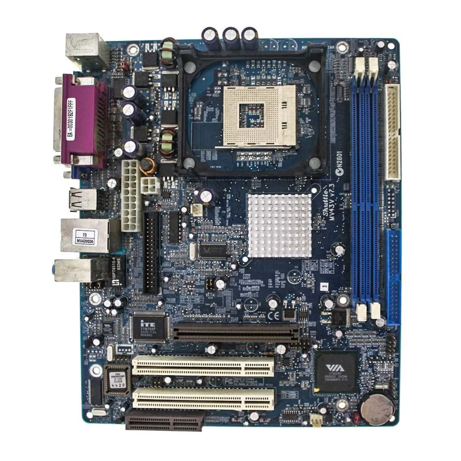
Then follow these steps designed to guide you through a quick and correct installation of your system. 3.1 Step-by-Step Installation Accessories Of MV43/MV43N CPU Clock - JP1A1/ JP1B1 Keyboard Power On- JP2 CPU FAN... -
Page 13: Step 1 Install The Cpu
Step 1 CPU Installation: This mainboard supports Intel Pentium 4, Socket 478 series CPU. Please follow the step as below to finish CPU installation. Be careful of CPU orientation when you plug it into CPU socket. 1. Pull up the CPU socket lever and up to 90-degree angle. CPU socket lever up to 90 degree 2. - Page 14 3. Press down the CPU socket lever and finish CPU installation. Note: If you do not match the CPU socket Pin 1 and CPU cut edge well, it may damage the CPU. 4. The Intel Pentium 4 /Celeron processor requires a set of heatsink/fan to en sure proper cooling of the processor.
-
Page 15: Step 2 Set Jumpers
Step 2. Set Jumpers The default jumper settings have been set for the common usage standard of this mainboard. Therefore, you do not need to reset the jumpers unless you require special adjustments as any of the following cases: 1. Clear CMOS 2. -
Page 16: Step 4 Install Peripherals In System Case
Step 4 Install Internal Peripherals in System Case Before you install and connect the mainboard into your system case, we recommend that you first assemble all the internal peripheral devices into the computer housing, including but not limited to the hard disk drive (IDE/ HDD), floppy disk drive (FDD), CD-ROM drive, and ATX power supply unit. -
Page 17: Step 5 Mount The Mainboard On The Computer Chassis
Step 5 Mount the Mainboard on the Computer Chassis 1. You may find that there are a lot of different mounting hole positions both on your computer chassis and on the mainboard. To choose correct mounting holes, the key point is to keep the back-panel of the mainboard in a close fit with your system case, as shown below. -
Page 18: Step 6 Connect Front Panel Switches/Leds/Speaker/Usb
Step 6 Connect Front Panel Switches/LEDs/USB You can find there are several different cables already existing in the system case and originating from the computer's front-panel devices (HDD LED, Power LED, Reset Switch, Audio Line-out, Microphone-in, or USB devices etc.) These cables serve to connect the front-panel switches, LEDs, and USB connectors to the mainboard's front-panel connectors group , as shown below. -
Page 19: Step 7 Connect Ide And Floppy Disk Drives
Step 7 Connect IDE and Floppy Disk Drives 1. IDE cable connector IDE2 IDE1 2. Floppy cable connector - 18 -... -
Page 20: Step 8 Connect Other Internal Peripherals
Step 8 Connect Other Internal Peripherals 1. CD-IN connectors Step 9 Connect the Power Supply 1. System power connector - 19 -... -
Page 21: Step 10 Install Add-On Cards In Expansion Slots
Step 10 Install Add-on Cards in Expansion Slots 1. Accelerated Graphics Port (AGP) Card 2. PCI Card 3. CNR Card - 20 -... -
Page 22: Step 11 Connect External Peripherals To Back Panel
Step 11 Connect External Peripherals to Back-Panel You are now ready to put the computer case back together and get on to the external peripherals connections to your system's back-panel. 1. PS/2 Mouse and PS/2 Keyboard 2. LAN Port 3. USB1/2 Ports 4. -
Page 23: Step 12 First Time System Boot Up
Step 12 First Time System Boot Up To assure the completeness and correctness of your system installation, you may check the above installation steps once again before you boot up your system for the first time. 1. Insert a bootable system floppy disk (DOS 6.2x, Windows 95/98/NT, or others) which contains FDISK and FORMAT utilities into the FDD. -
Page 24: Step 13 Install Drivers & Software Components
1. Insert the MV43/MV43N bundled CD-ROM into your CD-ROM drive. The autorun program will display the drivers main installation window on screen. 2. Choose "Install Mainboard MV43 Driver" bar to run into sub-menu for MV43 setup. 3. Choose "Install Mainboard MV43N Driver" bar to run into sub-menu for MV43N setup. -
Page 25: Jumper Settings
3.2 Jumper Settings Several hardware settings are made through the use of mini jumpers to con- nect jumper pins on the mainboard. Pin #1 could be located at any corner of each jumper, you just find the location with a white right angle which stands for pin 1#. -
Page 26: Jumpers & Connectors Guide
Jumpers & Connectors Guide Use the mainboard layout on page 11 to locate CPU socket, memory banks, expansion slots, jumpers and connectors on the mainboard during the instal- lation. The following list will help you to identify jumpers, slots, and connec- tors along with their assigned functions: B2~B3 B4~B6... - Page 27 Jumpers JBAT1 : Clear CMOS setting JP1A1/JP1B1 : CPU Clock setting : DRAM Voltage setting J2A/B/C/D : DDR/SDR DRAM Type Selector J3A/B/C/D : Keyboard Power On setting Back Panel Connectors : PS/2 keyboard port : PS/2 mouse port : RJ45 LAN Port (MV43N only) : 2 USB (Universal Serial Bus) ports PRINTER : Parallel port (DB25 female)
- Page 28 Internal Peripherals Connectors : Floppy disk drive interface IDE1 : IDE primary interface (Dual-channel) IDE2 : IDE secondary interface (Dual-channel) Other Connectors : ATX power connector CPU FAN : CPU fan connector SYSTEM FAN : System fan connector WOL1 : Wake-On-LAN connector WOM1 : Wake-On-Modem connector SIR1...
-
Page 29: Jumpers
Jumpers Clear CMOS Setting (JBAT1) JBAT1 is used to clear CMOS data. Clearing CMOS will result in the perma- nently erasing previous system configuration settings and the restoring origi- nal (factory-set) system settings. Pin 1-2 (Default) JBAT1 Pin 2-3 (Clear CMOS) Step 1. -
Page 30: Dram Voltage Setting (Jp1)
DRAM Voltage Setting (VCC) (JP1) & DDR/SDR DRAM Type Selector (J2A/B/C/D, J3A/B/C/D) JP1 is set to select voltage of DRAM. J2A/B/C/D and J3A/B/C/D are set to select the type of DDR or SDR DRAM. J2A/B/C/D J3A/B/C/D Open Pins 1-2 (2.5V DDR) Short Pins 1-2 (3V SDR) Note: You may use SDRAM or DDR SDRAM, but you can't use them simultaneously. -
Page 31: Keyboard Power On(Jp2)
Keyboard Power On(JP2) This jumper enables any keyboard activity to power up a system which is previously in a standby or sleep state. Disabled Short Pins 1-2 (5V) Enabled Short Pins 2-3 (5VSB) - 30 -... -
Page 32: Back-Panel Connectors Ps/2 Keyboard & Ps/2 Mouse Connectors
Back-Panel Connectors PS/2 Keyboard & PS/2 Mouse Connectors Two 6-pin female PS/2 keyboard & Mouse con- nectors are located at the rear panel of the mainboard. Depending on the computer hous- PS/2 Mouse ing you use (desktop or tower), the PS/2 Mouse connector is situated at the top of the PS/2 Keyboard connector when the mainboard is laid into a desktop, as opposed to a tower... -
Page 33: Vga Port Connector
VGA Connector One 15-pin VGA connector is located at the rear panel of the mainboard. VGA Port Line-Out Port Connector Line-Out is a stereo output port through which the combined signal of all internal and external audio sources on the board is Line-Out Port output. -
Page 34: Front-Panel Connectors
Front-Panel Connectors HDD LED Connector (HD_LED) Attach the connector cable from the IDE device LED to the 2-pin (HD_LED) header. The HDD LED lights up whenever an IDE device is active. SP_LED PW-BN HD_LED PANEL2 Note: Please notice all the LED connectors are directional. If your chassis s LED does not light up during running, please simply change to the opposite direction. -
Page 35: Hardware Reset Connector (Rst)
Hardware Reset Connector (RST) Attach the 2-pin hardware reset switch cable to the (RST) header. Pressing the reset switch causes the system to restart. SP_LED PW-BN HD_LED PANEL2 ATX Power On/Off Switch Connector (PW_BN) The Power On/Off Switch is a momentary type switch used for turning on or off the system ATX power supply. -
Page 36: Sleep Switch (J12)
Sleep Switch (J12) This header is connected to the sleep button for suspending the computer's activity if pushing the button. Or,the computer is automatically suspended after passing a period of time. LAN LED Indicator (J16) This connected is attached to LAN device that needs a LED indicator. Pins Assignment: 1,+2=Link LED +3,4=ACT LED... -
Page 37: Internal Peripherals Connectors
Internal Peripherals Connectors Enhanced IDE and Floppy Connectors The mainboard features two 40-pin dual-channel IDE device connectors (IDE1/IDE2) providing support for up to four IDE devices, such as CD-ROM and Hard Disk Drives (H.D.D.). This mainboard also includes one 34-pin floppy disk controller (FDC) to accommodate the Floppy Disk Drive (FDD). -
Page 38: Other Connectors
Other Connectors ATX Power Supply Connector (CN5) This motherboard uses 20-pin Pentium 4 standard ATX power header, CN5 and comes with another headers. A traditional ATX system should remain at power off stage when AC power resumes from power failure. In such case, if there is no an UPS to keep power-on, the kind of design is inconvenient for a network server or worksta- tion. -
Page 39: Cpu & System Fan Connector
CPU and System Fan connectors (CPU-FAN, SYSTEM-FAN) The mainboard provides two onboard 12V cooling fan power connectors to support CPU and System cooling fans. +12V SENSE CPU_FAN CPU FAN with rotate sense. System FAN with rotate sense. SYSTEM_FAN Note: Both cable wiring and type of plug may vary , which depends on the fan maker. -
Page 40: Wake-On Modem Connector (Wom1)
Wake-On-Modem Connector (WOM1) If you have installed a modem, use the cable provided with the modem to plug into the mainboard WOM1 connector. This enables the Wake On Modem(WOM) feature. When you system is in a power-saving mode, any modem signal automatically resumes the system. You must enable this item using the Power Management page of the Setup Utility. -
Page 41: Audio Cable Header (Cd1/Cd2)
Audio CD_IN Headers (CD1/CD2) Use the audio cable provided with the CD-ROM/DVD drive to connect to the mainboard CD-in connector CD1 or CD2. Pins Assignment:(CD1) 1=GND 2=CD IN L 3=GND 4=CD IN R Pins Assignment:(CD2) 1=CD IN L 2=GND 3=GND 4=CD IN R Front-Panel Microphone and Line_out Header (PANEL1) This header allows users to install auxiliary front-oriented microphone and line-... -
Page 42: System Memory Configuration
3.3 System Memory Configuration The MV43/MV43N mainboard has two 184-pin and two 168-pin DIMM slots that allow you to install from 64MB up to 2GB of system memory. Each 184-pin DIMM (Dual In-line Memory Module) slot can accommo- date 64MB, 128MB, 256MB, 512MB, and 1GB of PC1600/PC2100 compli- ant 2.5V single or double side 64-bit wide data path DDR SDRAM modules. -
Page 43: Software Utility
D:\Autorun.exe (assuming that your CD-ROM drive is drive D:) Navigation Bar Description: F Install Mainboard MV43 Driver - Installing VIA Chipset, VGA, Audio, USB2.0 drivers.. F Install Mainboard MV43N Driver - Installing VIA Chipset, VGA, Audio, USB2.0 , LAN drivers.. -
Page 44: Install Mainboard Software Driver
Insert the attached CD into your CD-ROM drive and the CD AutoRun screen should appear. If the AutoRun screen does not appear, double click on Autorun icon in My Computer to bring up Shuttle Mainboard Soft- ware Setup screen. Select using your pointing device (e.g. mouse) on the "Install Mainboard MV43 Driver"... -
Page 45: A Install Via Chipset Driver
4.2.A Install VIA Chipset Driver Select using your pointing device (e.g. mouse) on the “Install VIA Chipset Driver" bar to install VIA chipset driver. M V 4 3 MV43N Once you made your selection, a Setup window run the installation automatically. -
Page 46: B Install Vga Driver
4.2.B Install VGA Driver Select using your pointing device (e.g. mouse) on the “Install VGA Device Driver" bar to install VGA driver. M V 4 3 MV43N Once you made your selection, a Setup window run the installation automatically. When the copying files is done, make sure you reboot the system to take the installation effect. -
Page 47: C Install Audio Driver
4.2.C Install Audio Driver Select using your pointing device (e.g. mouse) on the “Install Audio Driver" bar to install AC'97 Audio driver. M V 4 3 MV43N Once you made your selection, a Setup window run the installation automatically. When the copying files is done, make sure you reboot the system to take the installation effect. -
Page 48: D Install Usb2.0 Driver
4.2.D Install USB2.0 Driver Select using your pointing device (e.g. mouse) on the “Install USB2.0 Driver" bar to install USB2.0 driver. M V 4 3 MV43N Once you made your selection, a Setup window run the installation automatically. When the copying files is done, make sure you reboot the system to take the installation effect. -
Page 49: E Install Lan Driver(Mv43N Only)
4.2.E Install LAN Driver(MV43N Only) Select using your pointing device (e.g. mouse) on the “Install LAN Driver" bar to install LAN driver. MV43N Once you made your selection, a Setup window run the installation automatically. When the copying files is done, make sure you reboot the system to take the installation effect. -
Page 50: View The User's Manual
Insert the attached CD into your CD-ROM drive and the CD AutoRun screen should appear. If the AutoRun screen does not appear, double click on AutoRun icon in My Computer to bring up Shuttle Mainboard Software Setup screen. Select using your pointing device (e.g. mouse) on the “Manual" bar. -
Page 51: Bios Setup
5 BIOS SETUP MV43/MV43N BIOS ROM has a built-in Setup program that allows users to modify the basic system configuration. This information is stored in battery- backed RAM so that it retains the Setup information even if the system power is turned off. -
Page 52: The Main Menu
5.2 The Main Menu Once you enter the AMIBIOS(tm) CMOS Setup Utility, the Main Menu will appear on the screen. The Main Menu allows you to select from several setup functions and two exit choices. Use the arrow keys to select among the items and press <Enter>... - Page 53 Load Best Performance Settings Fail Safe settings load the values required by the system for the O.K. per- formance. However, you can change the parameter through each Setup Menu. Features Setup This setup page includes all items of peripheral features. CPU PnP Setup This setup page includes all items of CPU PnP features.
-
Page 54: Standard Cmos Setup
Standard CMOS Setup The items in Standard CMOS Setup Menu are divided into 8 categories. Each category includes no, one or more than one setup items. Use the arrow keys to highlight the item and then use the <PgUp> or <PgDn>... - Page 55 See Master Options are in its sub-menu. Press <Enter> to enter the sub-menu of detailed options. See Slave Options are in its sub menu. Press <Enter> to enter the sub-menu of detailed options. Floppy Drive A/ Floppy Drive B Select the type of floppy disk drive installed in your system. Ø...
-
Page 56: Advanced Setup
ADVANCED SETUP This section allows you to configure your system for basic operation. You have the opportunity to select the system's default speed, boot-up sequence, keyboard operation, shadowing, and security. Quick Boot If you enable this item, the system starts up more quickly be elimination some of the power on test routines.Quick Power On Self Test (Enabled) Ø... - Page 57 BootUp Num-Lock This item determines if the Num Lock key is active or inactive at system start-up time. Ø The choice: Off or On . Floppy Drive Swap If you have two diskette drives installed and you enable this item, drive A becomes drive B and drive B becomes drive A.
- Page 58 SDRAM Frequency This item determines frequency of SDRAM memory. Ø The choice: Auto, 100MHz, 133 MHz. SDRAM CAS# Latency This item determines the operation of SDRAM memory CAS (column address strobe). It is recommended that you leave this item at the default value.
- Page 59 CLK GEN Spread Spectrum Use this item to set the system bus spread spectrum for the installed processor. Ø The choice: Enabled or Disabled. - 58 -...
-
Page 60: Power Management Setup
Power Management Setup ACPI Aware O/S This item supports ACPI (Advanced Configuration and Power management Interface). Use this item to enable or disable the ACPI feature. Ø The choice: Yes or No. Power Management Use this item to enable or disable a power management scheme. If you enable power management, you can use the items below to set the power management operation. - Page 61 Restore on AC/Power Loss This allow you to set whether you want your system to reboot after power has been interrupted Ø The choice: Power off, Power on or Last state. Resume On RTC Alarm / Date / Hour / Minute / Second The system can be turned off with a software command.
-
Page 62: Pci/Plug And Play Setup
PCI /Plug and Play Setup Plug and Play Aware O/S Enable this item if you are using an O/S that supports Plug and Play such as Windows 95 or 98. Ø The choice: Yes or No. Share Memory Size This item lets you allocate a portion of the main memory for the onboard VGA display application with three options of 8/16/32MB. -
Page 63: Load Optimal Setting
Load Optimal Settings When you press <Enter> on this item, you will get a confirmation dialog box with a message similar to: Load Optimal settings (Y/N) ? N Pressing 'Y' the Setup Utility loads a set of fail-safe default values. These default values are not very demanding and they should allow your system to function with most kinds of hardware and memory chips. -
Page 64: Featunes Setup
Features Setup OnBoard FDC Use this item to enable or disable the onboard floppy disk drive interface. Ø The choice: Enabled,Auto,Disabled . OnBoard Serial PortA Use this item to enable or disable the onboard COM1 serial port, and to assign a port address. Ø... - Page 65 Parallel Port IRQ Use this item to assign IRQ to the parallel port.a port address. Ø The choice: 7,5. Parallel Port DMA Use this item to assign a DMA channel to the parallel port. Ø The choice: N/A. OnBoard GAME Port This item enables or disables the I/O address for the GAME Port.
- Page 66 USB Device Legacy Support This item allows you to enable the USB device, if you have installed a USB device on the system board. Ø The choice: Disabled, No Mice, All Device. ThumbDrive Support for DOS This item allows user to use ThumbDvive under DOS Environment. Ø...
-
Page 67: Cpu Pnp Setup
CPU PnP Setup This page helps you manually configure the mainboard for the CPU. The system will automatically detect the type of installed CPU and make the appropriate adjustments to the items on this page. CPU BRAND This item show the Brand of CPU installed in your system. CPU Type This item show the Type of CPU installed in your system. -
Page 68: Hardware Monitor
Hardware Monitor On mainboards that support hardware monitoring, this item lets you monitor the parameters for critical voltages, critical temperatures, and fan speeds: System Hardware These fields provide you with information about the systems current operating status. You cannot make changes to these fields. The fields include Vcore Vcc2.5V... -
Page 69: Change Password
Change Password If you highlight this item and press Enter, a dialog box appears which lets you enter a Supervisor password. You can enter no more than six letters or numbers. Press Enter after you have typed in the password. A second dialog box asks you to retype the password for confirmation. -
Page 70: Exit
Password Disable If you select System at Security Option of BIOS Features Setup Menu, you will be prompted in entering the password whenever the system is rebooted or you try to enter Setup. If you select Setup at Security Option of BIOS Features Setup Menu, you will be prompted only when you try to enter Setup.
Need help?
Do you have a question about the MV43 and is the answer not in the manual?
Questions and answers