Table of Contents
Advertisement
Quick Links
Advertisement
Table of Contents

Related Manuals for Shuttle MS52


Summary of Contents for Shuttle MS52
- Page 1 MS52/MS52N & MS54/MS54N Pentium 4 Processor Based DDR MAIN BOARD User's Manual...
- Page 2 The information contained in this manual is provided for general use by the customers. Trademarks Shuttle is a registered trademark of Shuttle Inc. Intel, Pentium is a registered trademarks of Intel Corporation. SiS is a registered trademarks of SiS Corporation.
-
Page 3: Table Of Contents
2.1 SPECIFICATIONS ..................8 3 HARDWARE INSTALLATION ...............11 3.1 STEP BY STEP INSTALLATION ................11 Accessories of MS52/MS52N & MS54/MS54N........... 11 STEP 1 CPU Installation ................ 12 STEP 2 Set Jumpers ................14 STEP 3 Install DDR SDRAM System Memory........14 STEP 4 Install Peripherals in System Case .......... - Page 4 3.2 JUMPER SETTINGS ................. 24 JUMPERS & CONNECTORS GUIDE ............ 25 Jumpers Clear CMOS Setting (JP1) ..............28 BIOS Write Protection (JP3) ..............28 Back-Panel Connectors PS/2 Keyboard & PS/2 Mouse Connectors ..........29 COM1 Port Connector ................29 Parallel Port Connector ................29 Line-out port connector .................
- Page 5 ATX Power Supply Connectors (ATX1/ATX2) ........35 Audio CD_IN connectors (CDIN1/CDIN2) ..........35 Wake-on-Modem connector (WOM1) ............. 36 Wake-on-Lan connector (WOL1) ............36 Cooling Fan Connectors for CPU (CPUFAN1), Case (CASFAN1/ PWRFAN1) ................... 36 IR header (IR1) ..................37 3.3 SYSTEM MEMORY CONFIGURATION ............. 38 1.
- Page 6 PNP/PCI CONFIGURATION............... 65 PC HEALTH STATUS ................67 FREQUENCY/VOLTAGE CONTROL ............68 LOAD FAIL-SAFE DEFAULTS ..............69 LOAD OPTIMIZED DEFAULTS ..............69 SET PASSWORD ..................70 SAVE & EXIT SETUP ................71 EXIT WITHOUT SAVING ................71 - 4 -...
-
Page 7: What's In The Manual
WHAT’S IN THE MANUAL Quick Reference Hardware Installation >> Step-by-Step ..........Page 11 Jumper Settings >> A Closer Look ............Page 25 Drivers/Software Utilities >> How to Install ......... Page 39 BIOS Setup >> How to Configure ............Page 46 About This Manual For First-Time DIY System Builder ............ -
Page 8: Introduction
Experienced DIY User Congratulate on your purchase of the Shuttle MS52/MS52N & MS54/MS54N mainboard. You will find that installing your new Shuttle MS52/MS52N & MS54/ MS54N mainboard is just easy. Bundled with an array of onboard functions, the highly-integrated MS52/MS52N & MS54/MS54N mainboard provides you with a total solution to build the most stable and reliable system. -
Page 9: Item Checklist
1.2 Item Checklist: Check all items with you MS52/MS52N & MS54/MS54N mainboard to make sure nothing is missing. The complete package should include: PSKBM1 PSKBM1 CPU FAN1 CPU FAN1 A M P A M P COM1 COM1 LED1 - One piece of Shuttle MS52/MS52N &... -
Page 10: Features
2 FEATURES MS52/MS52N & MS54/MS54N mainboard is carefully designed for the demanding PC user who wants high performance and maximum intelligent features in a compact package. 2.1 Specifications - CPU Support Intel Pentium 4/Celeron, 478-pin processors with 400 MHz FSB.(MS54/ MS54N) Intel Pentium 4/Celeron, 478-pin processors with 400 /533MHz FSB.(MS52/... - Page 11 - CNR Expansion Slot Provides one Communication and Network Riser (CNR) slot. - 6 USB2.0 Interface Onboard Ø 2 USB connectors on back-panel and two sets of dual USB ports header on board. - I/O Interface Provides a variety of I/O interfaces: Ø...
- Page 12 - Advanced Configuration and Power Interface Features four power saving modes: S1 (Snoop), S3 (Suspend to RAM), S4 (Suspend to DISK), and S5 (Soft-Off). ACPI provides more efficient Energy Saving Features controlled by your operating system that supports OS Direct Power Management (OSPM) functionality.
-
Page 13: Hardware Installation
Then follow these steps designed to guide you through a quick and correct installation of your system. 3.1 Step-by-Step Installation Accessories Of MS52/MS52N & MS54/MS54N CPU Fan Two DDR DIMM Slots Connector-CPUFAN1... -
Page 14: Step 1 Cpu Installation
Step 1 CPU Installation: This mainboard supports Intel Pentium 4/Celeron , Socket 478 series CPU. Please follow the step as below to finish CPU installation. Be careful of CPU orientation when you plug it into CPU socket. 1. Pull up the CPU socket lever and up to 90-degree angle. CPU socket lever up to 90 degree 2. - Page 15 3. Press down the CPU socket lever and finish CPU installation. Note: If you do not match the CPU socket Pin 1 and CPU cut edge well, it may damage the CPU. 4. The Intel Pentium4/Celeron processor requires a set of heatsink/fan to ensure proper cooling of the processor.
-
Page 16: Step 2 Set Jumpers
Step 2. Set Jumpers The default jumper settings have been set for the common usage standard of this mainboard. Therefore, you do not need to reset the jumpers unless you require special adjustments as any of the following cases: 1. Clear CMOS 2. -
Page 17: Step 4 Install Peripherals In System Case
Step 4 Install Internal Peripherals in System Case Before you install and connect the mainboard into your system case, we recommend that you first assemble all the internal peripheral devices into the computer housing, including but not limited to the hard disk drive (IDE/ HDD), floppy disk drive (FDD), CD-ROM drive, and ATX power supply unit. -
Page 18: Step 5 Mount The Mainboard On The Computer Chassis
Step 5 Mount the Mainboard on the Computer Chassis 1. You may find that there are a lot of different mounting hole positions both on your computer chassis and on the mainboard. To choose correct mounting holes, the key point is to keep the back-panel of the mainboard in a close fit with your system case, as shown below. -
Page 19: Step 6 Connect Front Panel Switches/Leds/Speaker/Usb
Step 6 Connect Front Panel Switches/LEDs/Speaker/USB You can find there are several different cables already existing in the system case and originating from the computer front-panel devices (HDD LED, Power LED, Reset Switch, PC Speaker, or USB devices etc.) These cables serve to connect the front-panel switches, LEDs, and USB connectors to the mainboard front-panel connectors group ( USB2/USB3 and PANEL1, SPEAKER1,AUDIO1), as shown below. -
Page 20: Step 7 Connect Ide And Floppy Disk Drives
Step 7 Connect IDE and Floppy Disk Drives 1. IDE cable connector IDE2 IDE1 2. Floppy cable connector FDD1 Step 8 Connect Other Internal Peripherals 1. CDIN1/CDIN2 connectors CDIN2 CDIN1 - 18 -... -
Page 21: Step 9 Connect The Power Supply
2.IR header 3.SJ1 header 4. Wake On LAN and Wake On Modem headers WOM1 WOM1 WOL1 WOL1 - 19 -... -
Page 22: Step 10 Install Add-On Cards In Expansion Slots
Step 9 Connect the Power Supply 1. System power connector Step 10 Install Add-on Cards in Expansion Slots 1. AGP Card 2. PCI Card 3. CNR Card - 20 -... -
Page 23: Step 11 Connect External Peripherals To Back Panel
Step 11 Connect External Peripherals to Back-Panel You are now ready to put the computer case back together and get on to the external peripherals connections to your system's back-panel. PSKBM1 A M P A M P COM1 VGA1 1. PS/2 Mouse and PS/2 Keyboard 2. -
Page 24: Step 12 First Time System Boot Up
Step 12 First Time System Boot Up To assure the completeness and correctness of your system installation, you may check the above installation steps once again before you boot up your system for the first time. 1. Insert a bootable system floppy disk (DOS 6.2x, Windows 95/98/NT, or others) which contains FDISK and FORMAT utilities into the FDD. -
Page 25: Step 13 Install Drivers & Software Components
2000/ME/XP/NT operating systems only. Make sure your operating system is already installed before running the drivers installation CD-ROM programs. 1. Insert the MS52/MS52N & MS54/MS54N bundled CD-ROM into your CD-ROM drive. The autorun program will display the drivers main installation window on screen. -
Page 26: Jumper Settings
3.2 Jumper Settings Several hardware settings are made through the use of mini jumpers to con- nect jumper pins on the mainboard. Pin #1 could be located at any corner of each jumper, you just find the location with a white right angle which stands for pin 1#. -
Page 27: Jumpers & Connectors Guide
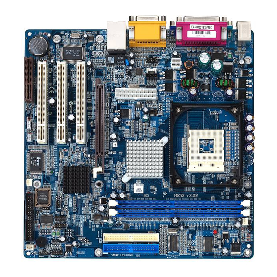
Jumpers & Connectors Guide Use the mainboard layout on page 11 to locate CPU socket, memory banks, expansion slots, jumpers and connectors on the mainboard during the installation. The following list will help you to identify jumpers, slots, and connectors along with their assigned functions: B1~B2 B3~B5 B6~B9... - Page 28 Jumpers : Clear CMOS setting : BIOS Write Protection setting Back Panel Connectors PSKBM1 : PS/2 keyboard port PSKBM1 : PS/2 mouse port COM1 : Serial port VGA1 : VGA port LPT1 : Parallel port LINE_OUT : Line-Out port LINE_IN : Line-In port MIC_IN : Mic-In port...
- Page 29 Other Connectors ATX1 : ATX 12V power connector ATX2 : ATX power connector CDIN1/CDIN2 : Primary/ Secondary CD_IN connectors WOM1 : Wake On Modem wakeup connector WOL1 : Wake On LAN wakeup connector CPUFAN1 : CPU fan connector CASFAN1 : Case fan connector 1 PWRFAN1 : Case fan connector 2 : Infrared header...
-
Page 30: Jumpers
Jumpers Clear CMOS Setting (JP1) JP1 is used to clear CMOS data. Clearing CMOS will result in the perma- nently erasing previous system configuration settings and the restoring origi- nal (factory-set) system settings. Pin 1-2 (Normal) Pin 2-3 (Clear CMOS) Step 1. -
Page 31: Back-Panel Connectors
Back-Panel Connectors PS/2 Keyboard & PS/2 Mouse Connectors B1~B2 Two 6-pin female PS/2 keyboard & Mouse connectors are located at the rear panel of the PS/2 Mouse mainboard. Depending on the computer housing you use (desktop or tower), the PS/2 Mouse connector is situated at the top of the PS/ 2 Keyboard connector when the mainboard is laid into a desktop, as opposed... -
Page 32: Line-In Port Connector
Line-In Port Connector Line-In is a stereo line-level input port that accepts a 1/8-inch TRS stereo plug. It can be used as a source for digital sound recording, a source to be mixed with the output, or both. Line-In Port Mic-In Port Connector Mic-In is a 1/8-inch jack that provides a mono input. -
Page 33: Front-Panel Connectors Atx Power On/Off Switch Connector (Pwrsw)
Front-Panel Connectors ATX Power On/Off Switch Connector (PWRSW) The Power On/ Off Switch is a momentary-type switch used for turning on or off the system's ATX power supply. Attach the connector cable from the Power Switch to the 2-pin Power Switch header on the mainboard. PANEL1 Green LED Connector (GRN LED) The Green LED (GRN LED) indicates that the system is currently in one of the... -
Page 34: Hardware Reset Connector (Rst)
Hardware Reset Connector (RST) Attach the 2-pin hardware reset switch cable to the Reset Switch header. Press- ing the reset switch causes the system to restart. PANEL1 Speaker Connector (SPEAKER1) Attach the PC speaker cable from the case to the 4-pin speaker connector (SPEAKER1). -
Page 35: Front-Oriented Microphone/Line-Out Port Header (Audio1)
Front-Oriented Microphone /Line-out Port Header (AUDIO1) This header allows the user to install auxiliary front-panel1 microphone and line-out ports for easier access. When frontpanel Microphone and line-out ports are not used, make sure to place two attached mini jumpers to the right position shown as below. -
Page 36: Internal Peripherals Connectors
Internal Peripherals Connectors Enhanced IDE and Floppy Connectors The mainboard features two 40-pin dual-channel IDE device connectors (IDE1/IDE2) providing support for up to four IDE devices, such as CD-ROM and Hard Disk Drives (H.D.D.). This mainboard also includes one 34-pin floppy disk controller (FLOPPY1) to accommodate the Floppy Disk Drive (FDD). -
Page 37: Other Connectors
Other Connectors ATX Power Supply Connectors (ATX1/ATX2) This motherboard uses 20-pin Pentium 4 standard ATX power header, ATX2 and comes with another header ATX1. ATX1 is with 2x2-pin +12 VPC ATX power supply header. Please make sure you plug in the right direction. ATX 1 ATX 2 A traditional ATX system should remain at power off stage when AC power resumes from... -
Page 38: Wake-On-Modem Connector (Wom1)
Wake-On-Modem Connector (WOM1) Attach a 3-pin connector through the Modem card which supports the Wake- On-Modem (WOM1) function. This function lets users wake up the connected system through the Modem card. Pins Assignment: 1=5VSB 2=GND WOM1 WOM1 3=SENSE Wake-On-LAN Connector (WOL1) Attach a 3-pin connector through the LAN card which supports the Wake-On- LAN (WOL1) function. -
Page 39: Ir Header (Ir1)
IR Header (IR1) If you have an Infrared device, this mainboard can implement IR transfer function. To enable the IR transfer function, follow these steps: Pins Assignment: 1=Not assigned 2=KEY 3=+5V 4=GND 5=IRTX 6=IRRX Note: Before connect your IR device, please be sure each IR on board pin allocation is matchable with the pin of the IR device. -
Page 40: System Memory Configuration
3.3 System Memory Configuration The MS52/MS52N & MS54/MS54N mainboard has two 184-pin DIMM slots that allow you to install from 128MB up to 2GB of system memory. Each 184-pin DIMM (Dual In-line Memory Module) Slot can accommodate , 128MB, 256MB, 512MB, and 1GB of PC1600/PC2100/PC2700 compliant 2.5V single (1 Bank) or double (2 Bank) side 64-bit wide data path DDR... -
Page 41: Software Utility
VGA drivers. F Install Mainboard MS54/N Software - Installing SIS AGP, Audio, VGA , and LAN drivers. F Manual - MS52/N & MS54/N Series mainboard user's manual in PDF format. F Link to Shuttle Homepage - Link to shuttle website homepage. -
Page 42: Install Mainboard Software
Autorun icon in My Computer to bring up Shuttle Mainboard Software Setup screen. Select using your pointing device (e.g. mouse) on the "Install Mainboard MS52/N Software" or "Install Mainboard MS52/N Software" bar to run into sub-menu. The Mainboard MS52/N & MS54/N Software include: [4.3] Install VGA Device Driver... -
Page 43: Install Vga Device Driver
4.3 Install VGA Device Driver Select using your pointing device (e.g. mouse) on the “Install VGA Device Driver" bar to install VGA driver. MS52/N MS54/N Once you made your selection, a Setup window run the installation automatically. When the copying files is done, make sure you reboot the system to take the installation effect. -
Page 44: Install Sis Agp Driver
4.4 Install SiS AGP Driver Select using your pointing device (e.g. mouse) on the “Install SiS AGP Driver " bar to install SiS AGP Driver. MS52/N MS54/N Once you made your selection, a Setup window run the installation automatically. When the copying files is done, make sure you reboot the system to take the installation effect. -
Page 45: Install Audio Device Driver
4.5 Install Audio Device Driver Select using your pointing device (e.g. mouse) on the “Install Audio Device Driver" bar to install Audio Device driver. MS52/N MS54/N Once you made your selection, a Setup window run the installation automatically. When the copying files is done, make sure you reboot the system to take the installation effect. -
Page 46: Install Lan Driver
4.6 Install LAN Driver (MS52N & MS54N only) Select using your pointing device (e.g. mouse) on the “Install LAN Driver” bar to install LAN driver. MS52/N MS54/N Once you made your selection, a Setup window run the installation automatically. When the copying files is done, make sure you reboot the system to take the installation effect. -
Page 47: View The User's Manual
4.8 View the User's Manual Select using your pointing device (e.g.mouse) on the "manaul" bar then choose "MS52/N+MS54/N Manual" bar to view user's manual. If you haven't get Acrobat Reader software installed, please choose "Install Acrobat Reader" bar to do setup before read the manual. -
Page 48: Bios Setup
5 BIOS SETUP MS52N/MS54N BIOS ROM has a built-in Setup program that allows users to modify the basic system configuration. This information is stored in battery- backed RAM so that it retains the Setup information even if the system power is turned off. -
Page 49: The Main Menu
5.2 The Main Menu Once you enter the AwardBIOS(tm) CMOS Setup Utility, the Main Menu will appear on the screen. The Main Menu allows you to select from several setup functions and two exit choices. Use the arrow keys to select among the items and press <Enter> to accept and enter the sub-menu. - Page 50 PnP / PCI Configurations This entry appears if your system supports PnP / PCI. PC Health Status This entry shows the current system temperature, Voltage, and FAN speed. Frequency/Voltage Control Use this menu to specify your settings for frequency/voltage control. Load Fail-Safe Defaults Use this menu to load the BIOS default values for the minimal/stable performance of your system to operate.
-
Page 51: Standard Cmos Features
Standard CMOS Features The items in Standard CMOS Setup Menu are divided into 10 categories. Each category includes no, one or more than one setup items. Use the arrow keys to highlight the item and then use the <PgUp> or <PgDn> keys to select the value you want in each item. Date <Month>... - Page 52 IDE Secondary Master Options are in its sub-menu. Press <Enter> to enter the sub-menu of detailed options. IDE Secondary Slave Options are in its sub menu. Press <Enter> to enter the sub-menu of detailed options. Drive A/Drive B Select the type of floppy disk drive installed in your system. Ø...
- Page 53 IDE HDD Auto-Detection Press <Enter> to auto-detect HDD on this channel. If detection is successful, it fills the remaining fields on this menu. Ø Press Enter IDE Primary Master Selecting 'manual' lets you set the remaining fields on this screen and select the type of fixed disk.
-
Page 54: Advanced Bios Features
Advanced BIOS Features This section allows you to configure your system for basic operation. You have the opportunity to select the system's default speed, boot-up sequence, keyboard operation, shadowing, and security. Virus Warning Allows you to choose the VIRUS Warning feature for IDE Hard Disk boot sector protection. - Page 55 Quick Power On Self Test This item speeds up Power-On Self Test (POST) after you power on the computer. If it is set to enabled, BIOS will shorten or skip some check items during POST. Ø The choice: Enabled, or Disabled. First/Second/Third Boot Device The BIOS attempts to load the operating system from the devices in the sequence selected in these items.
- Page 56 Typematic Rate Setting Keystrokes repeat at a rate determined by the keyboard controller. When this controller enabled, the typematic rate and typematic delay can be selected. Ø The choice: Enabled or Disabled. Typematic Rate (Chars/Sec) This item sets how many times the keystroke will be repented in a second when you hold the key down.
- Page 57 Report No FDD For Win 95 Whether report no FDD runs for Win 95 or not. Ø The choice: Yes or No. Small Logo(EPA) Show This item allows you to enable/disable the EPA Logo. Ø The choice: Enabled or Disabled. - 55 -...
-
Page 58: Advanced Chipset Features
Advanced Chipset Features This section allows you to configure the system based on the specific features of the installed chipset. This chipset manages bus speeds and access to sys- tem memory resources, such as DRAM and the external cache. It also coor- dinates communications between the conventional ISA bus and the PCI bus. - Page 59 DRAM Addr/Cmd Rate This item select the Cmd Rate of DDR SDRAM(1T/2T). Ø The Choice: Auto Mode, 1T, or 2T. Prefetch Caching This item enable/disable the Prefetch cache function of DRAM controller Ø The Choice: Enabled or Disabled. Memory Hole at 15M-16M You can reserve this area of system memory for ISA adapter ROM.
-
Page 60: Integrated Peripherals
Integrated Peripherals SIS OnChip IDE Device Options are in its sub-menu. Press <Enter> to enter the sub-menu of detailed options. Internal PCI/IDE This chipset contains and internal PCI IDE interface with support for two IDE channels. Ø The choice: Disabled, Primary, Secondary, or Both. IDE Primary/Secondary Master/Slave PIO The four IDE PIO (Programmed Input/Output) fields let you set a PIO mode (0-4) for each of the four IDE devices that the onboard IDE inter-... - Page 61 IDE DMA transfer access lnternal PCI/IDE field, above, is Disabled. Ø The choice: Enabled or Disabled. IDE Burst Mode Selecting Enabled reduces latency between each drive read/write cycle, but may cause instability in IDE subsystems that cannot support such fast performance. If you are getting disk drive errors, try setting this value to Disabled.
- Page 62 UART Mode Select This item allows you to select which mode for the Onboard Serial Port The choice: Normal, IrDA, ASKIR, or SCR. Ø UR2 Duplex Mode This item allows you to selects the IR half/full duplex function. Ø The choice: Full or Half. Onboard Parallel Port This item allows you to determine onboard parallel port controller I/O address setting.
- Page 63 USB Keyboard Support This item is used to defined USB Keyboard id Enabled or Disabled. Ø The Choice: Enabled or Disabled. Onboard LAN This item is used to enabled/disabled onboard LAN. Ø The Choice: Enabled or Disabled. Onboard LAN Boot ROM This item is used to enabled/disabled onboard LAN boot ROM.
-
Page 64: Power Management Setup
Power Management Setup The Power Management Setup allows you to configure your system to most effectively saving energy while operating in a manner consistent with your own style of computer use. ACPI Function This item allows you to enable/disable the Advanced Configuration and Power Management (ACPI) Ø... - Page 65 Video Off Method This determines the manner in which the monitor is blanked. Blank Screened This option only writes blanks to the video buffer. V/H SYNC+Blank This selection will cause the system to turn off the vertical and horizontal synchronization ports and write blanks to the video buffer.
- Page 66 IRQ 8 Break Suspend This field allows you to enable or disable monitoring of IRQ8 so that it does not awaken the system from a suspend mode. Ø The choice: Enabled, Disabled. RING/WOL/WOM PowerUp Control This item enabled/disabled LAN or modem activity to wakeup the system from a power saving mode.
-
Page 67: Pnp/Pci Configuration
PnP/PCI Configurations This section describes the configuration of PCI bus system. PCI or Personal Computer Interconnection is a system which allows I/O devices to operate at the speed CPU itself keeps when CPU communicating with its own special components. This section covers some very technical items, and it is strongly recommended that only experienced users should make any changes to the default settings. - Page 68 IRQ Resources When resources are controlled manually, assign each system interrupt a type, depending on the type of device using the interrupt. IRQ3/4/5/7/9/10/11/12/14/15 assigned This item allows you to determine the IRQ assigned to the ISA bus and is not available to any PCI slot. Legacy ISA for devices is compliant with the original PC AT bus specification;...
-
Page 69: Pc Health Status
PC Health Status Shutdown Temperature Enables you to set the maximum temperature the system can reach before powering down. Ø The choice: Disabled, 60 C/140 F,65 C/149 F,70 C/158 ¡C ¡C ¡C ¡C ¡C ¡C System Component Characteristics These fields provide you with information about the systems current operating status. -
Page 70: Frequency/Voltage Control
Frequency/Voltage Control CPU Clock Ratio This item allows you to adjust CPU Ratio. Min: 8 Max: 50 Ø Key in a DEC number: (Between Min and Max.) or left it auto detect. Auto Detect DIMM/PCI Clk This item allows you to enable/disable auto detection DIMM/PCI Clock. Ø... -
Page 71: Load Fail-Safe Defaults
Load Fail-Safe Defaults When you press <Enter> on this item, you will get a confirmation dialog box with a message similar to: Load Fail-Safe Defaults (Y/N) ? N Pressing 'Y' loads the BIOS default values for the most stable, minimal performance system operations. Load Optimized Defaults When you press <Enter>... -
Page 72: Set Password
Set Password This item is to set supervisor password. Please follow below steps. New Password Setting : 1. While pressing <Enter> key to start setting password function, a dialog box appears to ask you “Enter password: “. 2. Key in a new password now. However, the password can not be over eight characters or numbers. -
Page 73: Save & Exit Setup
Save & Exit Setup Pressing <Enter> on this item asks for confirmation: Save to CMOS and EXIT (Y/N)? Y Pressing "Y" stores the selections made in the menus of CMOS - a special section of memory that stays on after you turn your system off. The next time you boot your computer, the BIOS configures your system according to the Setup selections stored in CMOS.
Need help?
Do you have a question about the MS52 and is the answer not in the manual?
Questions and answers