
Related Manuals for Shuttle MB48


Summary of Contents for Shuttle MB48
- Page 1 MB48/MB48N & MB50/MB50N Intel Pentium 4/Celeron 478-pin Processor with 400/533 MHz FSB Based DDR MAINBOARD User's Manual...
- Page 2 The information contained in this manual is provided for general use by the customers. Trademarks Shuttle is a registered trademark of Shuttle Inc. Intel, Pentium, and Celeron are registered trademarks of Intel Corporation. PS/2 is a registered trademark of IBM Corporation.
-
Page 3: Table Of Contents
TABLE OF CONTENTS WHAT'S IN THE MANUAL ..............4 Quick Reference ....................4 About This Manual .................... 4 1 INTRODUCTION ................. 5 1.1 TO DIFFERENT USERS ................5 FIRST-TIME DIY SYSTEM BUILDER............. 5 EXPERIENCED DIY USER ................5 SYSTEM INTEGRATOR ................5 1.2 ITEM CHECKLIST: .................. - Page 4 USB3/4 Power-On Setting (JP5) ..............28 USB5/6 Power-On Setting (JP6) ..............28 Onboard LAN Setting (JP13) ..............29 Back-Panel Connectors PS/2 Mouse & PS/2 Keyboard Connectors ..........30 Parallel Port Connector ................30 COM1 Port Connector ................30 VGA Port Connector ................... 30 Line-Out Port Connector ................
- Page 5 Front-Panel Audio Connector (JP10) ............40 Serial Port Connector (COM2) ..............41 Extended USB Headers (JP7/JP8) ............. 41 3.3 SYSTEM MEMORY CONFIGURATION ............42 INSTALL MEMORY ..................42 UPGRADE MEMORY ................. 42 4 SOFTWARE UTILITY ...............43 4.1 Mainboard CD Overview ................43 4.2 Install Mainboard Software ..............
-
Page 6: What's In The Manual
WHAT'S IN THE MANUAL Quick Reference Hardware Installation >> Step-by-Step ..........Page 10 Jumper Settings >> A Closer Look ............Page 23 Software Utility >> How to Install ............Page 43 BIOS Setup >> How to Configure ............Page 52 About This Manual For First-Time DIY System Builder ............ -
Page 7: Introduction
Experienced DIY User Congratulate on your purchase of the MB48/N or MB50/N mainboard. You will find installing your new MB48/N or MB50/N mainboard is quite easy. Bundled with an array of onboard functions, the highly-integrated MB48/N or MB50/N mainboard provides you with a total solution to build the stablest and most reliable system. -
Page 8: Item Checklist
1.2 Item Checklist: Check all items with your MB48/N or MB50/N mainboard to make sure nothing is missing. A complete package should include: ! One Shuttle MB48/N or MB50/N Mainboard HE- M X2 0 21 0226 FAN2 CN 2 A T X 12 V... -
Page 9: Features
2 FEATURES MB48/N or MB50/N mainboard is dedicatedly designed for demanding PC users who desire high performance and maximum intelligent features in a compact package. 2.1 Specifications ! ! ! ! ! CPU Support Intel Pentium 4/Celeron, 478-pin processors with 400/533MHz FSB. - Page 10 ! ! ! ! ! I/O Interface Provides a variety of I/O interfaces: " 2 x PS/2 ports for Mouse and Keyboard " 1 x Parallel port " 1 x Serial port " 1 x VGA port " 1 x MIDI/Game port "...
- Page 11 ! ! ! ! ! Form Factor System board conforms to the Micro ATX specification. Board dimension: 244mm x 200mm. ! ! ! ! ! Advanced Features " Low EMI - Low EMI - Low EMI - Low EMI - Low EMI - Built in spread spectrum.
-
Page 12: Hardware Installation
Steps described herein will lead you to a quick and correct installation of your system. 3.1 Step-by-Step Installation Accessories Of MB48/N & MB50/N FSB Speed Configuration Setting - JP2 SOCKET 478... -
Page 13: Step 1 Cpu Installation
Step 1 CPU Installation: This mainboard supports Intel Pentium 4/Celeron Socket 478 series CPU. Please follow the step as listed below to finish the CPU installation. Note the CPU orientation as you place it into the CPU socket. 1. Pull up the CPU socket lever to 90-degree angle. CPU socket lever up to 90-degree angle 2. - Page 14 3. Press down the CPU socket lever and the CPU installation is completed. Note: Note: Note: The CPU might be damaged if you do not match the CPU Note: Note: socket Pin 1 and cut edge well. 4. Intel Pentium 4/Celeron processor requires a set of heatsink and fan to cool down the processor.
-
Page 15: Step 2 Set Jumpers
Step 2. Set Jumpers The default jumper settings have been set for the common usage standard of this mainboard. Therefore, you need not to reset the jumpers unless you re- quire special adjustments as any of the following cases: 1. Clear CMOS Setting 2. -
Page 16: Step 4 Install Internal Peripherals In System Case
Step 4 Install Internal Peripherals in System Case Before you place the mainboard into your system case, we recommend that you first assemble all the internal peripheral devices into the computer hous- ing, including, but not limited to, the hard disk drive (IDE/HDD), floppy disk drive (FDD), CD-ROM drive, and ATX power supply unit. -
Page 17: Step 5 Mount The Mainboard On The Computer Chassis
Step 5 Mount the Mainboard on the Computer Chassis 1. You may find there are a lot of mounting holes on your computer chassis and mainboard. To match the holes on both properly, the key point is to make the back-panel of the mainboard in a close fit with your system case, as shown below. -
Page 18: Step 6 Connect Front-Panel Leds/Switches/Speaker/Usbs
Step 6 Connect Front-Panel LEDs/Switches/Speaker/USBs You can find there are several cables existing in the system case and originat- ing from the front-panel devices (HDD LED, Green LED, Reset switch, PC Speaker, and USB devices etc.). These cables serve to connect the front-panel LEDs, switches, speaker, and USB connectors to JP12, JP7, and JP8, as shown below. -
Page 19: Step 7 Connect Ide And Floppy Disk Drives
Step 7 Connect IDE and Floppy Disk Drives IDE2 IDE1 1. IDE cable connectors 2. Floppy cable connector Step 8 Connect Other Internal Peripherals 1. CD_IN, AUX_IN, and CENTER/ BASS connectors CENTER/BASS J 3 CD_IN AUX_IN CD_IN - 17 -... -
Page 20: Step 9 Connect The Power Supplies
2. IR connector JP 3 Step 9 Connect the Power Supplies 1. System power connectors - 18 -... -
Page 21: Step 10 Install Add-On Cards In Expansion Slots
Step 10 Install Add-On Cards in Expansion Slots 1. Accelerated Grapics Port (AGP) Card (MB50/N only) (MB50/N only) (MB50/N only) (MB50/N only) (MB50/N only) 2. PCI Card - 19 -... -
Page 22: Step 11 Connect External Peripherals To Back-Panel
Step 11 Connect External Peripherals to Back-Panel You are now ready to connect the external peripherals to your system's back- panel. 1. PS/2 Mouse and PS/2 Keyboard 2. Parallel Port 3. COM Port 4. VGA Port 5. MIDI/Game Port 6. Audio Line-Out/Line-In/Mic-In Ports 7. -
Page 23: Step 12 System Boot Up For The First-Time
Step 12 System Boot Up For the First-Time To ensure your system completedly and correctly installed, please refer to the above installation steps once again before first booting up your system. 1. Insert a system-bootable floppy disk (DOS 6.2X, Windows 9X/NT, or others), which contains the FDISK and FORMAT utilities. -
Page 24: Step 13 Install Drivers & Software Components
2000/ME/NT/XP operating systems. Make sure your operating system is already installed before running the installation programs on CD-ROM. 1. Insert the MB48/N & MB50/N bundled CD-ROM into your CD-ROM drive. The auto-run program will display the main installation window on screen. -
Page 25: Jumper Settings
3.2 Jumper Settings Several hardware settings are made through the use of mini jumpers to con- nect jumper pins on the mainboard. Pin #1could be located at any corner of jumpers, and the corner with a white right angle stands for Pin #1. There are several types of Pin #1 as shown below: 3-pin and multi-pin (>3) jumpers shown as follows: Pin #1 to the left:... -
Page 26: Jumpers & Connectors Guide
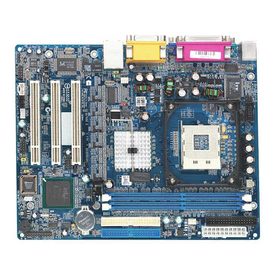
Jumpers & Connectors Guide Refer to the mainboard layout on page 10 and this section to help you iden- tify jumpers, slots, and connectors along with their assigned functions during installation: B2~B4 B5~B8 B9~B10 C1~C7 E7 E8 CPU/Memory/Expansion Slots Socket 478 : CPU socket for Pentium 4/Celeron, 478-pin processors DIMM1/2 : Two DIMM slots for 128, 256, 512 MB, and 1GB of 2.5V DDR SDRAM... -
Page 27: Jumpers
Jumpers : Clear CMOS setting : FSB speed configuration setting : USB3/4 power-on setting : USB5/6 power-on setting JP13 : Onboard LAN setting Back-Panel Connectors : PS/2 mouse port : PS/2 keyboard port PRN1 : Parallel port (printer) COM1 : Serial port VGA1 : VGA port LINE-OUT... - Page 28 Other Connectors JP11/CN2 : ATX power supply connectors FAN1 : CPU fan connector FAN2 : System fan connector FAN3 : System fan connector : IR header : Wake-On-LAN connector J3/J4 : Audio CD_IN connectors : Audio AUX_IN connector : Audio Center/Bass connector : SPDIF Ext.
-
Page 29: Clear Cmos Setting (Jp1)
Step 7. Turn on the system power (PC-->On). FSB Speed Configuration Setting (JP2) MB48/N or MB50/N provides JP2 to set front side bus at 400/533MHz. Insert the mini-jumper cap on pins 1-2 to set FSB at 400MHz. Removing the cap will set FSB at 533MHz. -
Page 30: Usb3/4 Power-On Setting (Jp5)
USB3/4 Power-On Setting (JP5) MB48/N or MB50/N provides JP5 to have USB devices connected to back- panel stay power-on from soft-off stage. Place the jumper cap on pins 2-3 to enable the USB device (USB 3&4) stay power-on on back-panel. -
Page 31: Onboard Lan Setting (Jp13)
Onboard LAN Setting (JP13) JP13 is used to enable or disable the built-in LAN adapter. Pin 1-2 (Enabled) Pin 2-3 (Disabled) - 29 -... -
Page 32: Back-Panel Connectors Ps/2 Mouse & Ps/2 Keyboard Connectors
! ! ! ! ! Back-Panel Connectors PS/2 Mouse & PS/2 Keyboard Connectors Two 6-pin female PS/2 Mouse & Keyboard PS/2 Mouse connectors are located on the rear panel of the mainboard. In a desktop computer, the PS/2 Mouse connector is situated on the top of the PS/2 Keyboard connector. -
Page 33: Line-In Port Connector
Line-In Port Connector Line-In is a stereo line-level input port that accepts a 1/8-inch TRS stereo plug. It can be used as a source for digital sound re- cording, a source to be mixed with the out- Line-In Port put, or both. Mic-In Port Connector Mic-In is a 1/8-inch jack that provides a mono input. -
Page 34: Front-Panel Connectors Hdd Led Connector (Hled)
! ! ! ! ! Front-Panel Connectors HDD LED Connector (HLED) Attach a connector cable from the IDE device LED to the 2-pin (HLED) header. The HDD LED lights up whenever an IDE device is active. Green LED Connector (GLED) The Green LED (GLED) indicates that the system is currently in one of the power saving modes (Doze/Standby/Suspend). -
Page 35: Hardware Reset Connector (Reset)
Hardware Reset Connector (Reset) Attach a cable to the 2-pin (Reset) header. Pressing the reset switch causes the system to restart. ATX Power On/Off Switch Connector (PWON) The Power On/Off Switch is a momentary type switch used for turning on or off the ATX power supply. -
Page 36: Epmi Connector (Epmi)
EPMI Connector (EPMI) A Hardware System Management Interface (EPMI) header may be attached to a 2-pin momentary switch. Press the switch to force the system into a power sav- ing mode; press it again to resume it to a normal operation situation. Power LED Connector (PLED) Attach a 3-pin Power LED connec- tor cable to the (PLED) header. -
Page 37: Internal Peripheral Connectors
! ! ! ! ! Internal Peripheral Connectors Enhanced IDE and Floppy Connectors (IDE1/2 & FDC) MB48/N or MB50/N mainboard features two 40-pin dual-channel IDE device connectors (IDE1/IDE2), providing support for up to four IDE devices, such as CD-ROM and Hard Disk Drive (HDD). This mainboard also includes one 34- pin floppy disk controller (FDC) to accommodate the Floppy Disk Drive (FDD). -
Page 38: Other Connectors Atx Power Supply Connectors (Jp11 & Cn2)
! ! ! ! ! Other Connectors ATX Power Supply Connectors (JP11 & CN2) This motherboard uses 20-pin Pentium 4 standard ATX power header (ATXPWR, JP11), and comes with the other one (ATX12V, CN2) header. Please make sure you plug each in the right direction. ATXPWR ATX12V JP11... -
Page 39: Cpu And System Fan Connectors (Fan1/2/3)
CPU and System Fan Connectors (FAN1/2/3) The mainboard provides three FAN1 onboard 12V cooling fan power connectors to support CPU (FAN1) & the system (FAN2/3). +12V FAN 3 SENSE Note: Both cable wiring and type of plug may vary, which depend on the fan maker. Keep in mind that the red wire should always be connected to the +12V header and the black wire to the ground... -
Page 40: Wake-On-Lan Connector (Cn1)
Wake-On-LAN Connector (CN1) Attach a 3-pin connector through the LAN card that supports the Wake-On- LAN (WOL, CN1) function. This function lets users wake up the system through the LAN card. Pin Assignments: 1=5VSB 2=GND 3=Ring# CN 1 WOL1 Audio CD_IN Connectors (J3/J4) Ports CD_IN (J3/J4) can be used to connect stereo audio inputs from CD-ROM, TV-tuner or MPEG card. -
Page 41: Audio Aux_In Connector (J5)
Audio AUX_IN Connector (J5) (White) Port J5 can be used to connect a stereo audio input from CD-ROM, TV-tuner or MPEG card. Pin Assignments: 1=AUXL 2=AGND 3=AGND 4=AUXR J5 AUX_IN Audio Center/Bass Connector (J2) Port J2 can be used to connect a cable attached to center/bass amplified speak- ers. -
Page 42: Spdif Ext. Header (Jp9)
SPDIF Ext. Header (JP9) Port JP9 can be used to connect a special device. 10 8 Pin Assignments: 1=+12V 6=GND 2=VCC 7=N/A 3=N/A 8=N/A 4=SPDIF-OUT 9=KEY 5=SPDIF-IN 10=GND JP9 SPD IF Ext . Front-Panel Audio Connector (JP10) This header allows users to install an auxiliary Front-Oriented Audio port for easier access. -
Page 43: Serial Port Connector (Com2)
Serial Port Connector (COM2) Port COM2 can be used to connect a serial port connector. COM 2 Extended USB Headers (JP7/JP8) Headers JP7 (USB 3&4) and JP8 (USB 5&6) are used to connect cables to USB connectors mounted on front-panel or back-panel. The USB cable is optional at the time of purchase. -
Page 44: System Memory Configuration
3.3 System Memory Configuration The MB48/N or MB50/N mainboard has two 184-pin DIMM slots that allow you to install from 128MB up to 2GB of system memory. Each 184-pin DIMM (Dual In-line Memory Module) slot can accommdate 128MB, 256MB, 512MB, and 1GB of PC1600/PC2100 (MB48/N), or of PC1600/PC2100/PC2700 (MB50/N) compliant 2.5V single or double side... -
Page 45: Software Utility
4 SOFTWARE UTILITY 4.1 Mainboard CD Overview Note: The CD contents attached in MB48/N or MB50/N mainboard are subject to change without notice. To start your mainboard CD disc, just insert it into your CD-ROM drive and the CD AutoRun screen should appear. If the AutoRun screen does not appear, double click or run D:\Autorun.exe (assuming that your CD-ROM... -
Page 46: Install Mainboard Software
Insert the attached CD into your CD-ROM drive and the CD AutoRun screen should appear. If the AutoRun screen does not appear, double click on Autorun icon in My Computer to bring up Shuttle Mainboard Software Setup screen. Select using your pointing device (e.g. mouse) on the"Install Mainboard MB48/N Software or Install Mainboard MB50/N Software"... -
Page 47: A Install Intel Chipset Driver
4.2.A Install Intel Chipset Driver Select using your pointing device (e.g. mouse) on the "Install Intel Chipset driver" bar to install the chipset driver. MB48/N MB50/N Once you made your selection, a Setup window run the installation automatically. When the copying files is done, make sure you reboot the system to take the installation effect. -
Page 48: B Install Intel Ultra Ata Driver
4.2.B Install Intel Ultra ATA Driver Select using your pointing device (e.g. mouse) on the "Install Intel Ultra ATA Driver" bar to install the ultra ATA driver. MB48/N MB50/N Once you made your selection, a Setup window run the installation automatically. -
Page 49: C Install Vga Driver
4.2.C Install VGA Driver Select using your pointing device (e.g. mouse) on the "Install VGA Driver" bar to install the VGA driver. MB48/N MB50/N Once you made your selection, a Setup window run the installation automatically. When the copying files is done, make sure you reboot the system to take the installation effect. -
Page 50: D Install Audio Driver
4.2.D Install Audio Driver Select using your pointing device (e.g. mouse) on the "Install Audio Dri- ver" bar to install the audio driver. MB48/N MB50/N Once you made your selection, a Setup window run the installation automatically. When the copying files is done, make sure you reboot the system to take the installation effect. -
Page 51: E Install Lan Driver (Mb48N/Mb50N Only)
4.2.E Install LAN Driver (MB48N/MB50N only) Select using your pointing device (e.g. mouse) on the "Install LAN Driver" bar to install the LAN driver. MB48N MB50N Once you made your selection, a Setup window run the installation automatically. When the copying files is done, make sure you reboot the system to take the installation effect. -
Page 52: F Install Usb 2.0 Driver
4.2.F Install USB 2.0 Driver Select using your pointing device (e.g. mouse) on the "Install USB 2.0 Driver" bar to install the USB 2.0 driver. MB48/N MB50/N Once you made your selection, a Setup window run the installation automatically. When the copying files is done, make sure you reboot the system to take the installation effect. -
Page 53: View The User's Manual
Select using your pointing device (e.g. mouse) on the "Manual" bar. Click on the "Install Acrobat Reader" bar if you need to install it, or click on the "MB48/N + MB50/N Manual" bar to view user's manual. - 51 -... -
Page 54: Bios Setup
5 BIOS SETUP MB48/N or MB50/N BIOS ROM has a built-in Setup program that allows users to modify the basic system configuration. This information is stored in battery-backed RAM so that it retains the Setup information even if the system power is turned off. -
Page 55: The Main Menu
5.2 The Main Menu Once you enter the Award BIOS(tm) CMOS Setup Utility, the Main Menu will appear on the screen. The Main Menu allows you to select from several setup functions and two exit choices. Use the arrow keys to select among the items and press <Enter>... - Page 56 PnP/PCI Configurations This option configures how PnP (Plug and Play ) and PCI expansion cards operate in your system. PC Health Status This entry shows the current system temperature, voltage, and fan speed. Frequency/Ratio Control Use this menu to set the clock speed and system bus for your system. Load Fail-Safe Defaults Use this menu to install fail-safe defaults for all appropriate items in the setup utility.
-
Page 57: Standard Cmos Features
Standard CMOS Features These items in Standard CMOS Setup Menu are divided into 10 catego- ries. Each category includes no, one or more than one setup items. Use the arrow keys to highlight the item and then use the <PgUp> or <PgDn>... - Page 58 IDE Secondary Master IDE Secondary Master IDE Secondary Master IDE Secondary Master IDE Secondary Master The options are in its sub-menu. Press <Enter> to enter the sub-menu of detailed options. IDE Secondary Slave IDE Secondary Slave IDE Secondary Slave IDE Secondary Slave IDE Secondary Slave The options are in its sub menu.
-
Page 59: Advanced Bios Features
Advanced BIOS Features This section allows you to configure your system for basic operation. Bios Write Protect This item let you enable or disable the Bios Write Protect. Ø The choice: Enabled or Disabled. Virus Warning Allows you to choose the VIRUS Warning feature for IDE Hard Disk boot sector protection. - Page 60 Quick Power On Self Test Quick Power On Self Test Quick Power On Self Test Quick Power On Self Test Quick Power On Self Test Enable this item to shorten the power on testing ( POST ) and have your system start up faster.
- Page 61 Typematic Rate Setting Typematic Rate Setting Typematic Rate Setting Typematic Rate Setting Typematic Rate Setting If this item is enabled, you can use the following two items to see the typematic rate and the typematic delay settings for your keyboard. "...
-
Page 62: Advanced Chipset Features
If you change the values incorrectly, you may introduce fatal errors or recurring instability into your system. MB48/N MB50/N DRAM Timing Selectable The value in this field depends on performance parameters of the installed memory chips ( DRAM ). - Page 63 Memory Frequency For Memory Frequency For Memory Frequency For This item defines SDRAM frequency. " The Choice: DDR200, DDR266, or Auto for MB48/N. " The Choice: DDR200, DDR266, DDR333, or Auto for MB50/N. System BIOS Cacheable System BIOS Cacheable System BIOS Cacheable...
- Page 64 Video BIOS Cacheable Video BIOS Cacheable Video BIOS Cacheable Video BIOS Cacheable Video BIOS Cacheable Selecting Enabled allows caching of the video BIOS , resulting in better system performance. However, if any program is written to this memory area, a system error may result. "...
-
Page 65: Integrated Peripherals
Integrated Peripherals These options display items that define the operation of peripheral components on the system's input / output ports. On-Chip Primary/Secondary PCI IDE Use these items to enable or disable the PCI IDE channels that are integrated on the mainboard. Ø... - Page 66 Use this item to specify whether your graphics adapter is installed in one of the PCI slots or is integrated on the mainboard. " The choice: PCI Slot or Onboard for MB48/N. " The choice: PCI Slot or Onboard/AGP for MB50/N.
- Page 67 Onboard Serial Port 1/2 Onboard Serial Port 1/2 Onboard Serial Port 1/2 Onboard Serial Port 1/2 Onboard Serial Port 1/2 Used to assign an I/O address and interrupt request (IRQ) for the on- board serial port1/2 (COM1/2). " The choice: Disabled, 3F8/IRQ4, 2F8/IRQ3, 3E8/IRQ4, 2E8/IRQ3, or Auto.
-
Page 68: Power Management Setup
Power Management Setup The Power Management Setup allows you to configure your system to most effectively saving energy while operating in a manner consistent with your own style of computer use. ACPI Function (Enabled) This item allows you to enable the ACPI (Advanced Configuration and Power Management ) feature. - Page 69 Run VGABIOS if S3 Resume (Auto) Run VGABIOS if S3 Resume (Auto) Run VGABIOS if S3 Resume (Auto) Run VGABIOS if S3 Resume (Auto) Run VGABIOS if S3 Resume (Auto) Allows the system to initialize a VGA BIOS from S3 (Suspend to RAM) sleep state.
- Page 70 Power On by Ring Power On by Ring Power On by Ring Power On by Ring Power On by Ring Determines if the system will resume by a modem ring. " The choice: Enabled or Disabled. Wake Up On LAN Wake Up On LAN Wake Up On LAN Wake Up On LAN...
-
Page 71: Pnp/Pci Configurations
PNP/PCI Configurations This category configures how PnP and PCI operate in your system. Correctly setting up the IRQ and DMA (both PnP and PCI use) assign- ments will make your system work stably. It is strongly recommended that only technical users make changes to the default settings. Reset Configuration Data When enabled, any PnP configuration data stored in the BIOS will be cleared from memory, with new data created. -
Page 72: Pc Health Status
PC Health Status Shutdown Temperature Enables you to set the maximum temperature the system can reach before powering down. Ø The choice: 60°C/140°F, 65°C/149°F, 70°C/158°F, or 75°C/ 167°F. The following items provide you with information about the current operating status on your system. You cannot make any changes to one of them, including: CPU Vcore Fan 1 Speed... -
Page 73: Frequency/Ratio Control
Frequency/Ratio Control CPU Clock Ratio The item defines a multiplier for the system FSB frequency. The formula is presented as follows: Multiplier X FSB Frequency = CPU Clock Speed For example, a processor at 450MHz and FSB frequency at 100MHz ought to set the multiplier at 4.5 for: 4.5 (Multiplier) X 100MHz (FSB Frequency) = 450MHz (CPU Clock Speed). -
Page 74: Load Fail-Safe Defaults
Load Fail-Safe Defaults When you press <Enter> on this item, you will see a dialog box with a message similar to: Load Fail-Safe Defaults (Y/N)? N Press <Y> and <Enter> to install the defaults, and v.v. Load Optimized Defaults When you press <Enter> on this item, you will see a dialog box with a message similar to: Load Optimized Defaults (Y/N)? N Press <Y>... -
Page 75: Save & Exit Setup
No Password Setting: No Password Setting: No Password Setting: No Password Setting: No Password Setting: If you want to disable the password, just press <Enter> as a password input is requested. If You Forget Password: If You Forget Password: If You Forget Password: If You Forget Password: If You Forget Password: If you forget the password, the only way to access the system is to clear...
Need help?
Do you have a question about the MB48 and is the answer not in the manual?
Questions and answers