Table of Contents
Advertisement
Advertisement
Table of Contents

Related Manuals for Shuttle MV43V


Summary of Contents for Shuttle MV43V
- Page 1 MV43V/MV43VN Pentium 4 Processor Based DDR/SDR MAIN BOARD User's Manual...
- Page 2 The information contained in this manual is provided for general use by the customers. Trademarks Shuttle is a registered trademark of Shuttle Inc. Intel Pentium is a registered trademarks of Intel Corporation. VIA is a registered trademarks of VIA Corporation.
- Page 3 Statement of Shuttle Mainboard via the EMI Test Shuttle mainboards have been via the EMI test in terms of series of regulations: EN55022/ CISPR22/AS/NZS3548 Class B, EN55024 (1998/AS/NZS), EN4252.1 (1994), EN61000, ANSI C63.4 (1992), CFR47 Part 15 Subpart B, and CNS13438 (1997). The items tested are illus- trated as follows: (A) Voltage: AC 110V/60HZ &...
- Page 4 (D) Supported Host Peripherals: Host Peripheral Product Name Model Name FCC ID Case KF45A Power Supply (300W) ENP-0730 (ATX12V) 100002885 IBM HDD (30.7GB) 91024UB YKFY7981 3892I168 MITSUMI FDD D353M SONY VCD Player CDU4811 3892A291 AGP Card Winfast Geforce 2MX 3892C520 Power Cable Detachable and Shielded...
-
Page 5: Table Of Contents
2.1 SPECIFICATIONS ..................8 3 HARDWARE INSTALLATION ............11 3.1 STEP BY STEP INSTALLATION ..............11 Accessories of MV43V/MV43VN ............11 STEP 1 Install the CPU ................12 STEP 2 Set Jumpers ................13 STEP 3 Install DDR SDRAM System Memory........13 STEP 4 Install Peripherals in System Case .......... - Page 6 3.2 JUMPER SETTINGS ................. 23 JUMPERS & CONNECTORS GUIDE ............ 24 Jumpers Clear CMOS Setting (JBAT1) ............... 27 CPU Clock Setting (JP1A1/JP1B1) ............27 Keyboard Power On(JP2) ..............28 Back-Panel Connectors PS/2 Keyboard & PS/2 Mouse Connectors ..........29 Parallel Port Connector ................29 COM1 Port Connector ................
- Page 7 CPU & System Fan Connectors (CPU-FAN, SYSTEM-FAN) ....36 Serialinfrared Port (SIR1)............... 36 Audio Cable Header (CD2) ..............37 Front-Panel Microphone and Line_out Header (PANEL1) ...... 37 3.3 SYSTEM MEMORY CONFIGURATION ............. 38 1. INSTALL MEMORY ................38 2. UPGRADE MEMORY ................ 38 4 SOFTWARE UTILITY ..............
- Page 8 CPU PNP SETUP ..................62 HARDWARE MONITOR ................63 CHANGE PASSWORD ................64 EXIT ......................65 - 4 -...
-
Page 9: What's In The Manual
WHAT'S IN THE MANUAL Quick Reference Hardware Installation >> Step-by-Step ..........Page 11 Jumper Settings >> A Closer Look ............Page 23 Drivers/Software Utilities >> How to Install ......... Page 39 BIOS Setup >> How to Configure ............Page 47 About This Manual For First-Time DIY System Builder ............ -
Page 10: Introduction
Experienced DIY User Congratulate on your purchase of the Shuttle MV43V/MV43VN mainboard. You will find that installing your new Shuttle MV43V/MV43VN mainboard is just easy. Bundled with an array of onboard functions, the highly-integrated MV43V/MV43VN mainboard provides you with a total solution to build the most stable and reliable system. -
Page 11: Item Checklist
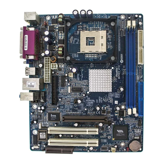
1.2 Item Checklist: Check all items with your MV43V/MV43VN mainboard to make sure noth- ing is missing. The complete package should include: - One piece of Shuttle MV43V/MV43VN Mainboard KB_MS COM1 COM2 PRT F D C USB1 LINE1 R T M 3 6 0 - 1 0 7 R... -
Page 12: Features
2 FEATURES MV43V/MV43VN mainboard is carefully designed for the demanding PC user who wants high performance and maximum Intelligent features in a compact package. 2.1 Specifications - CPU Support Intel Pentium 4, 478-pin processors with 400/533 MHz FSB. - Chipset Features VIA P4M266A N.B. - Page 13 - AGP Expansion Slots Provides one 32-bit AGP slot which supports 4X AGP devices. - CNR Expansion Slot Provides one CNR (Communication/ Network Riser) slot. - 6 USB 2.0 Interface Onboard Ø 4 USB connectors on back-panel and one set of dual USB ports headers on mid-board.
- Page 14 - Advanced Configuration and Power Interface Features four power saving modes: S1 (Snoop), S4 (Suspend to DISK), and S5 (Soft-Off). ACPI provides more efficient Energy Saving Features controlled by your operating system that supports OS Direct Power Management (OSPM) functionality. - System BIOS Provides licensed AMI BIOS 2Mb Flash core and supports Green PC, Desk- top Management Interface (DMI).
-
Page 15: Hardware Installation
Then follow these steps designed to guide you through a quick and correct installation of your system. 3.1 Step-by-Step Installation Accessories Of MV43V/MV43VN CPU Clock - JP1A1/ JP1B1 12V ATX Power Connector Socket 478... -
Page 16: Step 1 Install The Cpu
Step 1 CPU Installation: This mainboard supports Intel Pentium 4/Celeron Socket 478 series CPU. Please follow the steps as follows to finish CPU installation. Note the CPU orientation when you plug it into CPU socket. 1. Pull up the CPU socket lever to 90-degree angle. CPU socket lever up to 90-degree angle 2. -
Page 17: Step 2 Set Jumpers
Step 2. Set Jumpers The default jumper settings have been set for the common usage standard of this mainboard. Therefore, you do not need to reset the jumpers unless you require special adjustments as any of the following cases: 1. Clear CMOS 2. -
Page 18: Step 4 Install Peripherals In System Case
Step 4 Install Internal Peripherals in System Case Before you install and connect the mainboard into your system case, we recommend that you first assemble all the internal peripheral devices into the computer housing, including but not limited to the hard disk drive (IDE/ HDD), floppy disk drive (FDD), CD-ROM drive, and ATX power supply unit. -
Page 19: Step 5 Mount The Mainboard On The Computer Chassis
Step 5 Mount the Mainboard on the Computer Chassis 1. You may find that there are a lot of different mounting hole positions both on your computer chassis and on the mainboard. To choose correct mounting holes, the key point is to keep the back-panel of the mainboard in a close fit with your system case, as shown below. -
Page 20: Step 6 Connect Front Panel Switches/Leds/Speaker/Usb
Step 6 Connect Front Panel Switches/LEDs/USB You can find there are several different cables already existing in the system case and originating from the computer's front-panel devices (HDD LED, Power LED, Reset Switch, Audio Line-out, Microphone-in, or USB devices etc.) These cables serve to connect the front-panel switches, LEDs, and USB connectors to the mainboard's front-panel connectors group , as shown below. -
Page 21: Step 7 Connect Ide And Floppy Disk Drives
Step 7 Connect IDE and Floppy Disk Drives 1. IDE cable connector IDE2 IDE1 2. Floppy cable connector - 17 -... -
Page 22: Step 8 Connect Other Internal Peripherals
Step 8 Connect Other Internal Peripherals 1. CD-IN connectors 2. IR Header SIR1 Step 9 Connect the Power Supply ATX12V 1. System power connectors - 18 -... -
Page 23: Step 10 Install Add-On Cards In Expansion Slots
Step 10 Install Add-on Cards in Expansion Slots 1. Accelerated Graphics Port (AGP) Card 2. PCI Card 3. CNR Card - 19 -... -
Page 24: Step 11 Connect External Peripherals To Back Panel
Step 11 Connect External Peripherals to Back-Panel You are now ready to put the computer case back together and get on to the external peripherals connections to your system's back-panel. 1. PS/2 Mouse and PS/2 Keyboard 2. Parallel Port 3. COM1 Port 4. -
Page 25: Step 12 First Time System Boot Up
Step 12 First Time System Boot Up To assure the completeness and correctness of your system installation, you may check the above installation steps once again before you boot up your system for the first time. 1. Insert a bootable system floppy disk (DOS 6.2x, Windows 95/98/NT, or others) which contains FDISK and FORMAT utilities into the FDD. -
Page 26: Step 13 Install Drivers & Software Components
1. Insert the MV43V/MV43VN bundled CD-ROM into your CD-ROM drive. The autorun program will display the drivers main installation window on screen. 2. Choose "Install Mainboard MV43V Driver" bar to run into sub- menu for MV43V setup. 3. Choose "Install Mainboard MV43VN Driver" bar to run into sub- menu for MV43VN setup. -
Page 27: Jumper Settings
3.2 Jumper Settings Several hardware settings are made through the use of mini jumpers to con- nect jumper pins on the mainboard. Pin #1 could be located at any corner of each jumper, you just find the location with a white right angle which stands for pin 1#. -
Page 28: Jumpers & Connectors Guide
Jumpers & Connectors Guide Use the mainboard layout on page 11 to locate CPU socket, memory banks, expansion slots, jumpers and connectors on the mainboard during the instal- lation. The following list will help you to identify jumpers, slots, and connec- tors along with their assigned functions: B2~B4 B6~B7... -
Page 29: Jumpers
Jumpers JBAT1 : Clear CMOS setting JP1A1/JP1B1 : CPU Clock setting : Keyboard Power On setting Back Panel Connectors : PS/2 keyboard port : PS/2 mouse port PRINTER : Parallel port (DB25 female) COM1 : Serial port 1 : VGA Port : 2 USB (Universal Serial Bus) ports : RJ45 LAN Port (MV43VN Only) : 2 USB (Universal Serial Bus) ports... - Page 30 Other Connectors CN5/PJ1 : ATX power connectors CPU FAN : CPU fan connector SYSTEM FAN : System fan connector SIR1 : IR header : Onboard Audio Connector PANEL1 : Front-Panel Audio Line_Out/ Mic_In connector - 26 -...
-
Page 31: Clear Cmos Setting (Jbat1)
Jumpers Clear CMOS Setting (JBAT1) JBAT1 is used to clear CMOS data. Clearing CMOS will result in the perma- nently erasing previous system configuration settings and the restoring origi- nal (factory-set) system settings. Pin 1-2 (Default) Pin 2-3 (Clear CMOS) JBAT1 Step 1. -
Page 32: Keyboard Power On(Jp2)
Keyboard Power On(JP2) This jumper enables any keyboard activity to power up a system which is previously in a standby or sleep state. Disabled Short Pins 1-2 (5V) Enabled Short Pins 2-3 (5VSB) - 28 -... -
Page 33: Back-Panel Connectors Ps/2 Keyboard & Ps/2 Mouse Connectors
Back-Panel Connectors PS/2 Keyboard & PS/2 Mouse Connectors Two 6-pin female PS/2 keyboard & Mouse con- nectors are located at the rear panel of the mainboard. Depending on the computer hous- PS/2 Mouse ing you use (desktop or tower), the PS/2 Mouse connector is situated at the top of the PS/2 Keyboard connector when the mainboard is laid into a desktop, as opposed to a tower... -
Page 34: Lan Port Connector(Mv43Vn Only)
LAN Port LAN Port Connector(MV43VN Only) This mainboard can accommodate one de- vice on LAN. Attach a 10/100 baseT cable to the RJ45 at the back-panel of your computer. USB Port 4 USB3/USB4 Port Connectors This mainboard offers 2 USB ports on back panel. -
Page 35: Front-Panel Connectors
Front-Panel Connectors HDD LED Connector (HD_LED) Attach the connector cable from the IDE device LED to the 2-pin (HD_LED) header. The HDD LED lights up whenever an IDE device is active. PANEL2 PW_BN HD_LED SP_LED Note: Please notice all the LED connectors are directional. If your chassis’s LED does not light up during running, please simply change to the opposite direction. -
Page 36: Hardware Reset Connector (Rst)
Hardware Reset Connector (RST) Attach the 2-pin hardware reset switch cable to the (RST) header. Pressing the reset switch causes the system to restart. PANEL2 PW_BN HD_LED SP_LED ATX Power On/Off Switch Connector (PW_BN) The Power On/Off Switch is a momentary type switch used for turning on or off the system ATX power supply. -
Page 37: Speaker Connector (Spk1)
Speaker Connector (SPK1) Attach the PC speaker cable from the case to the 4-pin speaker connector (SPK1). Pins Assignment: 1=SPKR 2=NC 3=GND 4=+5V Extended USB Header (USB2) The mainboard has USB ports installed on the rear edge I/O port array. Some computer cases have a special module that mounts USB ports at the front of the case. -
Page 38: Internal Peripherals Connectors
Internal Peripherals Connectors Enhanced IDE and Floppy Connectors The mainboard features two 40-pin dual-channel IDE device connectors (IDE1/IDE2) providing support for up to four IDE devices, such as CD-ROM and Hard Disk Drives (H.D.D.). This mainboard also includes one 34-pin floppy disk controller (FDC) to accommodate the Floppy Disk Drive (FDD). -
Page 39: Other Connectors
Other Connectors ATX Power Supply Connector (CN5/PJ1) This motherboard uses 20-pin (CN5)Pentium 4 standard ATX power header, and other PJ1 with 2x2-pin +12V PC ATX power supply headers. Please make sure you plug in the right direction. ATX12V A traditional ATX system should remain at power off stage when AC power resumes from power failure. -
Page 40: Cpu & System Fan Connectors (Cpu-Fan, System-Fan)
CPU and System Fan connectors (CPU-FAN, SYSTEM-FAN) The mainboard provides two onboard 12V cooling fan power connectors to support CPU and System cooling fans. +12V SENSE SYSTEM_FAN Note: Both cable wiring and type of plug may vary , which depends on the fan maker. Keep in mind that the red wire should always be connected to the +12V header and the black wire to the ground (GND) -
Page 41: Audio Cable Header (Cd2)
Audio CD_IN Headers (CD2) Use the audio cable provided with the CD-ROM/DVD drive to connect to the mainboard CD-in connector CD2. Pins Assignment:(CD2) 1=CD IN L 2=GND 3=GND 4=CD IN R Front-Panel Microphone and Line_out Header (PANEL1) This header allows users to install auxiliary front-oriented microphone and line- out ports for easier access. -
Page 42: System Memory Configuration
3.3 System Memory Configuration The MV43V/MV43VN mainboard has two 184-pin DIMM slots that allow you to install from 64MB up to 2GB of system memory. Each 184-pin DIMM (Dual In-line Memory Module) slot can accommodate 64MB, 128MB, 256MB, 512MB, and 1GB of PC1600/PC2100 compliant 2.5V single or double side DDR SDRAM modules. -
Page 43: Software Utility
4 SOFTWARE UTILITY 4.1 Mainboard CD Overview Note: The CD contents attached in MV43V/MV43VN mainboard are sub ject to change without notice. To start your mainboard CD disc, just insert it into your CD-ROM drive and the CD AutoRun screen should appear. If the AutoRun screen does not appear, double click or run D:\Autorun.exe (assuming that your CD-ROM... -
Page 44: Install Mainboard Software Driver
Insert the attached CD into your CD-ROM drive and the CD AutoRun screen should appear. If the AutoRun screen does not appear, double click on Autorun icon in My Computer to bring up Shuttle Mainboard Software Setup screen. Select using your pointing device (e.g. mouse) on the "Install Mainboard MV43V Driver"... -
Page 45: A Install Via Chipset Driver
4.2.A Install VIA Chipset Driver Select using your pointing device (e.g. mouse) on the “Install VIA Chipset Driver" bar to install VIA chipset driver. MV43V MV43VN Once you made your selection, a Setup window run the installation automatically. When the copying files is done, make sure you reboot the system to take the installation effect. -
Page 46: B Install Vga Driver
4.2.B Install VGA Driver Select using your pointing device (e.g. mouse) on the “Install VGA Device Driver" bar to install VGA driver. MV43V MV43VN Once you made your selection, a Setup window run the installation automatically. When the copying files is done, make sure you reboot the system to take the installation effect. -
Page 47: C Install Audio Driver
4.2.C Install Audio Driver Select using your pointing device (e.g. mouse) on the “Install Audio Driver"” bar to install AC'97 Audio driver. MV43V MV43VN Once you made your selection, a Setup window run the installation automatically. When the copying files is done, make sure you reboot the system to take the installation effect. -
Page 48: D Install Usb2.0 Driver
4.2.D Install USB2.0 Driver Select using your pointing device (e.g. mouse) on the “Install USB2.0 Driver"” bar to install USB2.0 driver. MV43V MV43VN Once you made your selection, a Setup window run the installation automatically. When the copying files is done, make sure you reboot the system to take the installation effect. -
Page 49: E Install Lan Driver(Mv43Vn Only)
4.2.E Install LAN Driver(MV43VN Only) Select using your pointing device (e.g. mouse) on the “Install LAN Driver” bar to install LAN driver. MV43VN Once you made your selection, a Setup window run the installation automatically. When the copying files is done, make sure you reboot the system to take the installation effect. -
Page 50: View The User's Manual
Insert the attached CD into your CD-ROM drive and the CD AutoRun screen should appear. If the AutoRun screen does not appear, double click on AutoRun icon in My Computer to bring up Shuttle Mainboard Software Setup screen. Select using your pointing device (e.g. mouse) on the “Manual" bar. -
Page 51: Bios Setup
5 BIOS SETUP MV43V/MV43VN BIOS ROM has a built-in Setup program that allows users to modify the basic system configuration. This information is stored in battery- backed RAM so that it retains the Setup information even if the system power is turned off. -
Page 52: The Main Menu
Please be noted that the content of this manual is subject to change without notice in advance. 5.2 The Main Menu Once you enter the AMIBIOS(tm) CMOS Setup Utility, the Main Menu will appear on the screen. The Main Menu allows you to select from several setup functions and two exit choices. -
Page 53: Featunes Setup
Load Optimal Settings Optimal settings load the values required by the System for the fail-safe default values. However, you can change the parameter through each Setup Menu. Load Best Performance Settings Fail Safe settings load the values required by the system for the best performance and default values. -
Page 54: Standard Cmos Setup
Standard CMOS Setup The items in Standard CMOS Setup Menu are divided into 8 categories. Each category includes no, one or more than one setup items. Use the arrow keys to highlight the item and then use the <PgUp> or <PgDn>... - Page 55 Sec Slave Options are in its sub menu. Press <Enter> to enter the sub-menu of detailed options. Floppy Drive A/ Floppy Drive B Select the type of floppy disk drive installed in your system. Ø The choice: None, 360K, 5.25 in, 1.2M, 5.25 in, 720K, 3.5 in, 1.44M, 3.5 in, or 2.88M, 3.5 in.
-
Page 56: Advanced Setup
ADVANCED SETUP This section allows you to configure your system for basic operation. You have the opportunity to select the system's default speed, boot-up sequence, keyboard operation, shadowing, and security. Quick Boot If you enable this item, the system starts up more quickly be elimination some of the power on test routines.Quick Power On Self Test (Enabled) Ø... - Page 57 BootUp Num-Lock This item determines if the Num Lock key is active or inactive at system start-up time. Ø The choice: Off or On . Floppy Drive Swap If you have two diskette drives installed and you enable this item, drive A becomes drive B and drive B becomes drive A.
- Page 58 SDRAM Timing By SPD This item allows you to enable or disable the SDRAM timing defined by the Serial Presence Detect electrical Ø The choice: Enabled or Disabled . SDRAM Frequency This item determines frequency of SDRAM memory. Ø The choice: Auto, 100MHz, 133 MHz. SDRAM CAS# Latency This item determines the operation of SDRAM memory CAS (column address strobe).
- Page 59 Auto Detect DIMM/PCI CIK When this item is enabled, BIOS will disable the clock signal of free DIMM/PCI slots. Ø The choice: Enabled or Disabled. CLK GEN Spread Spectrum Use this item to set the system bus spread spectrum for the installed processor.
-
Page 60: Power Management Setup
Power Management Setup ACPI Aware O/S This item supports ACPI (Advanced Configuration and Power management Interface). Use this item to enable or disable the ACPI feature. Ø The choice: Yes or No. Power Management Use this item to enable or disable a power management scheme. If you enable power management, you can use the items below to set the power management operation. - Page 61 PWR Button<4 secs Pressing the power button for more than 4 seconds forces the system to enter the Soft-Off state when the system has"hung". Ø The choice: Instant-Off or Delay 4 Sec. . Restore On AC/Power Loss This allow you to set whether you want your system to reboot after power has been interrupted.
-
Page 62: Pci/Plug And Play Setup
PCI /Plug and Play Setup Plug and Play Aware O/S Enable this item if you are using an O/S that supports Plug and Play such as Windows 95 or 98. Ø The choice: Yes or No. Share Memory Size This item lets you allocate a portion of the main memory for the onboard VGA display application with three options of 8/16/32MB. -
Page 63: Load Optimal Setting
Load Optimal Settings When you press <Enter> on this item, you will get a confirmation dialog box with a message similar to: Load Optimal settings (Y/N) ? N Pressing 'Y' the Setup Utility loads a set of fail-safe default values. These default values are not very demanding and they should allow your system to function with most kinds of hardware and memory chips. - Page 64 Features Setup OnBoard FDC Use this item to enable or disable the onboard floppy disk drive interface. Ø The choice: Enabled,Auto,Disabled . OnBoard Serial PortA Use this item to enable or disable the onboard COM1 serial port, and to assign a port address. Ø...
- Page 65 Parallel Port IRQ Use this item to assign IRQ to the parallel port.a port address. Ø The choice: 7,5. Parallel Port DMA Use this item to assign a DMA channel to the parallel port. Ø The choice: N/A. OnBoard GAME Port This item enables or disables the I/O address for the GAME Port.
-
Page 66: Cpu Pnp Setup
USB Device Legacy Support This item allows you to enable the USB device, if you have installed a USB device on the system board. Ø The choice: Disabled, No Mice, All Device. ThumbDrive Support for DOS This item allows user to use ThumbDvive under DOS Environment. Ø... -
Page 67: Hardware Monitor
Hardware Monitor On mainboards that support hardware monitoring, this item lets you monitor the parameters for critical voltages, critical temperatures, and fan speeds: System Hardware These fields provide you with information about the systems current operating status. You cannot make changes to these fields. The fields include Vcore Vcc2.5V... -
Page 68: Change Password
Change Password If you highlight this item and press Enter, a dialog box appears which lets you enter a Supervisor password. You can enter no more than six letters or numbers. Press Enter after you have typed in the password. A second dialog box asks you to retype the password for confirmation. -
Page 69: Exit
Password Disable If you select System at Security Option of BIOS Features Setup Menu, you will be prompted in entering the password whenever the system is rebooted or you try to enter Setup. If you select Setup at Security Option of BIOS Features Setup Menu, you will be prompted only when you try to enter Setup.
Need help?
Do you have a question about the MV43V and is the answer not in the manual?
Questions and answers