Table of Contents
Advertisement
Quick Links
Advertisement
Table of Contents

Related Manuals for Shuttle MB47N


Summary of Contents for Shuttle MB47N
- Page 1 MB47N Pentium 4 /Celeron, 478-Pin Processor Based MAIN BOARD User's Manual...
- Page 2 The information contained in this manual is provided for general use by the customers. Trademarks Shuttle is a registered trademark of Shuttle Inc. Intel, Pentium is a registered trademarks of Intel Corporation. PS/2 is a registered trademark of IBM Corporation.
-
Page 3: Table Of Contents
2.1 SPECIFICATIONS ..................5 3 HARDWARE INSTALLATION ............. 8 3.1 STEP BY STEP INSTALLATION ..............8 Accessories of MB47N ................8 STEP 1 Install the CPU ................9 STEP 2 Set Jumpers ................11 STEP 3 Install DDR SDRAM System Memory ........11 STEP 4 Install Peripherals in System Case .......... - Page 4 Back-Panel Connectors PS/2 Keyboard & PS/2 Mouse Connectors ..........27 LAN Port Connector ................27 USB0/USB1 Port Connectors ..............27 COM Port Connector ................27 VGA Port Connector ..................28 Parallel Port Connector................28 Line-Out Port Connector ................. 28 Line-In Port Connector ................28 Mic-In Port Connector ................
- Page 5 2. UPGRADE MEMORY ................. 36 4 SOFTWARE UTILITY ...............3 7 4.1 Mainboard CD Overview ................37 4.2 The mainboard Software Driver ............... 38 4.3 Install INTEL INF Driver ................39 4.4 Install IDE Driver ..................40 4.5 Install VGA Driver..................41 4.6 Install Audio Device Driver ...............
-
Page 6: Introduction
1 INTRODUCTION 1.1 Item Checklist: Check all items with you MB47N mainboard to make sure nothing is miss- ing. The complete package should include: P S K B M1 D I M M 2 C P U F A N 1... -
Page 7: Features
2 FEATURES MB47N mainboard is carefully designed for the demanding PC user who wants high performance and maximum intelligent features in a compact package. 2.1 Specifications ! ! ! ! ! CPU Support Intel Pentium 4/Celeron, 478-pin processors with 400 MHz FSB. - Page 8 ! ! ! ! ! I/O Interface Provides a variety of I/O interfaces: " 2PS/2 ports for mouse and keyboard " 1Parallel port " 1Serial port " 1VGA port " 1MIDI/GAME port. " 1LAN port " 2USB ports " 1Mic-in port "...
- Page 9 ! ! ! ! ! Form Factor System board conforms to Micro ATX specification. Board dimension: 244mm x 244mm. ! ! ! ! ! Advanced Features " Low EMI - Low EMI - Low EMI - Low EMI - Low EMI - Built in spread spectrum and automatic clock shut-off of unused PCI/SDRAM slots to reduce EMI.
-
Page 10: Hardware Installation
Then follow these steps designed to guide you through a quick and correct installation of your system. 3.1 Step-by-Step Installation Accessories Of MB47N VID4 - VID0 SOCKET 478 PWR FAN 1... -
Page 11: Step 1 Install The Cpu
Step 1 CPU Installation: This mainboard supports Intel Pentium 4/Celeron , Socket 478 series CPU. Please follow the step as below to finish CPU installation. Be careful of CPU orientation when you plug it into CPU socket. 1. Pull up the CPU socket level and up to 90-degree angle. CPU socket level up to 90 degree 2. - Page 12 3. Press down the CPU socket level and finish CPU installation. Note: Note: Note: If you do not match the CPU socket Pin 1 and CPU cut Note: Note: edge well, it may damage the CPU. - 10 -...
-
Page 13: Step 2 Set Jumpers
Step 2. Set Jumpers The default jumper settings have been set for the common usage standard of this mainboard. Therefore, you do not need to reset the jumpers unless you require special adjustments as any of the following cases: 1. Clear CMOS 2. -
Page 14: Step 4 Install Peripherals In System Case
Step 4 Install Internal Peripherals in System Case Before you install and connect the mainboard into your system case, we recommend that you first assemble all the internal peripheral devices into the computer housing, including but not limited to the hard disk drive (IDE/ HDD), floppy disk drive (FDD), CD-ROM drive, and ATX power supply unit. -
Page 15: Step 5 Mount The Mainboard On The Computer Chassis
Step 5 Mount the Mainboard on the Computer Chassis 1. You may find that there are a lot of different mounting hole positions both on your computer chassis and on the mainboard. To choose correct mounting holes, the key point is to keep the back-panel of the mainboard in a close fit with your system case, as shown below. -
Page 16: Step 6 Connect Front Panel Switches/Leds/Speaker/Usb/Audio1
Step 6 Connect Front Panel Switches/LEDs/Speaker/USB/AUDIO1 You can find there are several different cables already existing in the system case and originating from the computers front-panel devices (HDD LED, Power LED, Reset Switch, PC Speaker, or USB devices etc.) These cables serve to connect the front-panel switches, LEDs, and USB connectors to the mainboard’... - Page 17 USB 3 15. VCC 16. USBP2 - 17. USBP2+ 18. GROUND 19. KEY " 20. USBPWR1 21. USBP3 - 22. USBP3+ 23. GROUND & 24. NC SPEAKER1 1. SIGNAL 4 3 2 1 2. KEY 3. Ground SPEAKER 1 4. VCC AUDIO 1 1.
-
Page 18: Step 7 Connect Ide And Floppy Disk Drives
Step 7 Connect IDE and Floppy Disk Drives IDE2 IDE1 1. IDE cable connector 2. Floppy cable connector FDD I Step 8 Connect Other Internal Peripherals 1. CD-IN1/CD-IN2 connectors CD-IN 2 CD-IN 1 - 16 -... -
Page 19: Step 9 Connect The Power Supply
Step 9 Connect the Power Supply ATX 1 1. System power connector ATX 12V Step 10 Install Add-on Cards in Expansion Slots 1. PCI Card 2. CNR Card - 17 -... -
Page 20: Step 11 Connect External Peripherals To Back Panel
Step 11 Connect External Peripherals to Back-Panel You are now ready to put the computer case back together and get on to the external peripherals connections to your system back-panel. 1. PS/2 Mouse and PS/2 Keyboard 2. Parallel Port 3. COM Port 4. -
Page 21: Step 12 Install Drivers & Software Components
2000/ME/NT operating systems only. Make sure your operating system is already installed before running the drivers installation CD-ROM programs. 1. Insert the MB47N bundled CD-ROM into your CD-ROM drive. The auto-run program will display the drivers main installation window on screen. -
Page 22: Jumper Settings
3.2 Jumper Settings Several hardware settings are made through the use of mini jumpers to con- nect jumper pins on the mainboard. Pin #1 could be located at any corner of each jumper, you just find the location with a white right angle which stands for pin 1#. -
Page 23: Jumpers&Connectors Guide
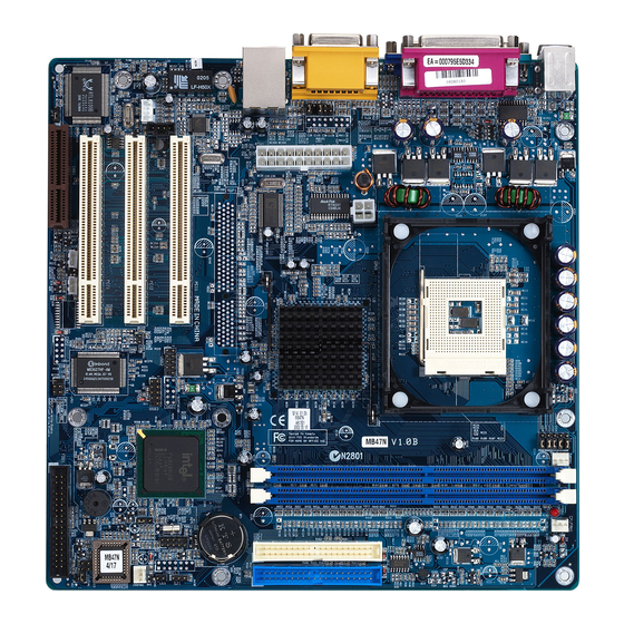
Jumpers&Connectors Guide Use the mainboard layout on page 11 to locate CPU socket, memory banks, expansion slots, jumpers and connectors on the mainboard during the instal- lation. The following list will help you to identify jumpers, slots, and connec- tors along with their assigned functions: B4~B6 B7~B10 B2~B3... - Page 24 Jumpers : Clear CMOS setting : BIOS flash protect jumper : Select onboard LAN )" VID4~VID0 : CPU Core voltage selector jumper Back Panel Connectors : PS/2 keyboard port : PS/2 mouse port : RJ45 LAN Port : 2 USB (Universal Serial Bus) ports COM1 : Serial ports 1 *"...
- Page 25 CASFAN : Chassis fan connector : Infrared cable header WOM1 : Wake On Modem wake up connector -" WOL1 : Wake On LAN wake up connector CDIN1 : CD_IN connector(WHITE), Panasonic Type CDIN2 : CD_IN connector(BLACK), Sony Type - 23 -...
-
Page 26: Jumpers
Jumpers $ $ $ $ $ Clear CMOS Setting (JP1) JP1 is used to clear CMOS data. Clearing CMOS will result in the perma- nently erasing previous system configuration settings and the restoring origi- nal (factory-set) system settings. Pin 1-2 (Default) Pin 2-3 (Clear CMOS) Step 1. -
Page 27: Lan Select On Board Setting(Jp4)
LAN Select on Board Setting (JP4) JP4 is used to enable or disable built-in LAN adapter. Pin 1-2 (Enable) Pin 2-3 (Disable) Core Voltage Selector Jumper Setting )" (VID4~VID0) VID4~VID0 is used to set the CPU voltage manually to improve the CPU performance. However, don't change the VID4~VID0 setting if you aren't familiar with the CPU. - Page 28 VID4 VID4 VID4 VID4 VID3 VID3 VID3 VID3 VID2 VID2 VID2 VID2 VID1 VID1 VID1 VID1 VID0 VID0 VID0 VID0 VDAC VDAC VDAC VDAC 1,2 close 1,2 close 1,2 close 1,2 close 1,2 close Auto open open open open open open open open...
-
Page 29: Back-Panel Connectors Ps/2 Keyboard & Ps/2 Mouse Connectors
Back-Panel Connectors $ $ $ $ $ PS/2 Keyboard & PS/2 Mouse Connectors Two 6-pin female PS/2 keyboard & Mouse connectors are located at the rear panel of the mainboard. Depending on the computer housing you use (desktop or tower), the PS/2 Mouse connector is situated at the top of the PS/2 Keyboard connector when the mainboard is laid into a desktop, as opposed to a tower where the PS/2 Mouse connector is located at the right of the PS/2... -
Page 30: Vga Port Connector
VGA Port Connector One 15-pin VGA connector is located at the rear panel of mainboard. VGA Port Parallel (Printer) Port Connector Parallel Port One DB25 female parallel connector is lo- cated at the rear panel of the mainboard. Plug the connection cable from your parallel device (printer, scanner, etc.) into this connec- fo xc o n n tor. - Page 31 MIDI Instrument Connection MIDI Instrument Connection MIDI Instrument Connection MIDI Instrument Connection MIDI Instrument Connection You will need a MIDI adapter to connect a MIDI compatible instrument to the sound card. The MIDI adapter can in turn be connected to the Joystick/MIDI port.
-
Page 32: Front-Panel Connectors Speaker Connector (Speaker)
Front-Panel Connectors $ $ $ $ $ Speaker Connector (SPEAKER) Attach the PC speaker cable from the case to the 4-pin speaker connector (SPEAKER). SPEAKER Panel1 Connector The panel1 connector provides a standar set of switch and LED connectors commonly found on ATX or micro-ATX cases. PANEL 1 Empty Power... -
Page 33: Audio1 Connector
Audio1 Connector This header allows the user to install auxiliary front-oriented microphone and line-out ports for easier access. Either the Mic and Line-out connector on back-panel or JP19 header are availbale at the same time. If you would like to use this JP19 header on front-panel, please remove all jumpers from PANEL1 and install your special Extra Mic/Line-out cable instead. -
Page 34: Internal Peripherals Connectors Enhanced Ide And Floppy Connector
Internal Peripherals Connectors $ $ $ $ $ Enhanced IDE and Floppy Connectors The mainboard features two 40-pin dual-channel IDE device connectors (IDE1/IDE2) providing support for up to four IDE devices, such as CD-ROM and Hard Disk Drives (H.D.D.). This mainboard also includes one 34-pin floppy disk controller (FDD1) to accommodate the Floppy Disk Drive (FDD). -
Page 35: Other Connectors
$% Other Connectors ATX Power Supply Connector (ATX1 and ATX12V) This motherboard uses 20-pin Pentium 4 standard ATX power header, ATX1 and comes with another ATX12V headers. Please make sure you plug in the right direction. ATX1 ATX12V ATX 1 ATX 12V A traditional ATX system should remain at power off stage when AC power resumes from power failure. -
Page 36: Cpu, Power, Cas Fan Connectors
CPU, Power, CAS Fan connectors The mainboard provides four onboard 12V cooling fan power connectors to support CPU, Power, and Chassis cooling fans. Note: Note: Note: Note: Note: Both cable wiring and type of plug may vary , which depends on the fan maker. Keep in mind that the red wire should always be connected to the +12V header and the black wire to the ground (GND) header. -
Page 37: Wake-On Modem Connector (Wom1)
Wake-On-Modem Connector (WOM1) -" Attach a 3-pin connector through the Modem card which supports the Wake- On-Wodem (WOM1) function. This function lets users wake up the connected system through the Modem card. Pins Assignment: WOM1 1=5VSB 2=Ground 3=Wake_up Wake-On-LAN Connector (WOL1) Attach a 3-pin connector through the LAN card which supports the Wake-On- LAN (WOL1) function. -
Page 38: System Memory Configuration
3.3 System Memory Configuration The MB47N mainboard has two 184-pin DIMM slots that allow you to install from 128MB up to 2GB of system memory. Each 184-pin DIMM (Dual In-line Memory Module) Slot can accommdate 128MB,256MB, 512MB and 1GB of PC1600/PC2100 compliant 2.5V single or double side 64-bit wide data path DDR SDRAM modules. -
Page 39: Software Utility
4 SOFTWARE UTILITY 4.1 Mainboard CD Overview Note: Note: Note: The CD contents attached in MB47N mainboard are subject to Note: Note: change without notice. To start your mainboard CD disc, just insert it into your CD-ROM drive and the CD AutoRun screen should appear. If the AutoRun screen does not appear, double click or run D:\Autorun.exe (assuming that your CD-ROM... -
Page 40: The Mainboard Software Driver
If the AutoRun screen does not appear, double click on My Computer My Computer Shuttle Mainboard Software Shuttle Mainboard Software Autorun icon in My Computer My Computer My Computer to bring up Shuttle Mainboard Software Shuttle Mainboard Software Shuttle Mainboard Software Setup Setup Setup Setup Setup screen. -
Page 41: Install Intel Inf Driver
4.3 Install INTEL INF Driver Select using your pointing device (e.g. mouse) on the "Install INTEL INF "Install INTEL INF "Install INTEL INF "Install INTEL INF "Install INTEL INF Driver" Driver" Driver" Driver" Driver" bar to install INTEL INF driver. Once you made your selection, a Setup window run the installation automatically. -
Page 42: Install Ide Driver
4.4 Install IDE Driver Select using your pointing device (e.g. mouse) on the “Install Intel Ultra Install Intel Ultra Install Intel Ultra Install Intel Ultra Install Intel Ultra ATA Driver ATA Driver ATA Driver ATA Driver ATA Driver" bar to install Ultra ATA IDE driver. Once you made your selection, a Setup window run the installation automatically. -
Page 43: Install Vga Driver
4.5 Install VGA Driver Select using your pointing device (e.g. mouse) on the “Install VGA Device Install VGA Device Install VGA Device Install VGA Device Install VGA Device Driver Driver Driver Driver Driver" bar to install VGA driver. - 41 -... -
Page 44: Install Audio Device Driver
4.6 Install Audio Device Driver Select using your pointing device (e.g. mouse) on the “Install Audio De- Install Audio De- Install Audio De- Install Audio De- Install Audio De- vice Driver vice Driver vice Driver vice Driver vice Driver" bar to install Audio driver. Once you made your selection, a Setup window run the installation automatically. -
Page 45: Install Lan Driver
4.7 Install LAN Driver Select using your pointing device (e.g. mouse) on the “Install LAN Driver Install LAN Driver Install LAN Driver Install LAN Driver” Install LAN Driver bar to install LAN driver. Once you made your selection, a Setup window run the installation automatically. - Page 46 Install Win98 LAN driver The LAN Device Driver can't be set up automatically, you need double click on My Computer -> Control Pnael -> System icon to bring up System Properties screen. Select tab "Device Manager". You will find a yellow "?" mark at PCI Ethernet Controller, that means the driver is not recognize.
- Page 47 Please choose "Display a list of the drivers in a specific location, so you can select the driver you want" to the manual install driver, and click on "Next" bar to continue. Select "Network adapters" bar for LAN device and click on "Next" bar to continue.
- Page 48 Select "Realtek RTL8139 [A/B/C/ "Realtek RTL8139 [A/B/C/ "Realtek RTL8139 [A/B/C/ "Realtek RTL8139 [A/B/C/ "Realtek RTL8139 [A/B/C/ 8130] PCI Fast Ethernet NIC" 8130] PCI Fast Ethernet NIC" 8130] PCI Fast Ethernet NIC" 8130] PCI Fast Ethernet NIC" 8130] PCI Fast Ethernet NIC" to "OK"...
- Page 49 Install WinNT4.0 LAN drivers Install WinNT4.0 LAN drivers Install WinNT4.0 LAN drivers Install WinNT4.0 LAN drivers Install WinNT4.0 LAN drivers The LAN Device Driver can't be set up automatically, you need double click on Desktop Network Network Network Network icon to bring up Network Setup Wizard Network Setup Wizard Network Setup Wizard Network Setup Wizard screen.
- Page 50 Make sure "Realtek RTL8139 [A/B/C/ "Realtek RTL8139 [A/B/C/ "Realtek RTL8139 [A/B/C/ "Realtek RTL8139 [A/B/C/ "Realtek RTL8139 [A/B/C/ 8130] PCI Fast Ethernet Adapter" 8130] PCI Fast Ethernet Adapter" 8130] PCI Fast Ethernet Adapter" 8130] PCI Fast Ethernet Adapter" 8130] PCI Fast Ethernet Adapter" driver, "Close"...
-
Page 51: View The User's Manual
Install Acrobe Reader the “Install Acrobe Reader Install Acrobe Reader Install Acrobe Reader" bar if you need to install acrobe reader. Then click on "MB47N Manual" "MB47N Manual" "MB47N Manual" "MB47N Manual" bar to view user's manual. "MB47N Manual" - 49 -... -
Page 52: Bios Setup
5 BIOS SETUP MB47N BIOS ROM has a built-in Setup program that allows users to modify the basic system configuration. This information is stored in battery-backed RAM so that it retains the Setup information even if the system power is turned off. -
Page 53: The Main Menu
5.2 The Main Menu Once you enter the Award BIOS(tm) CMOS Setup Utility, the Main Menu will appear on the screen. The Main Menu allows you to select from several setup functions and two exit choices. Use the arrow keys to select among the items and press <Enter>... - Page 54 PnP / PCI Configurations This option configures how PnP (Plug and Play ) and PCI expansion cards operate in your system. PC Health Status This entry shows the current system temperature, voltage, and fan speed. Frequency / Voltage Control Use this menu to set the clock speed and system bus for your system. Load Fail-Safe Defaults Use this menu to install fail-safe defaults for all appropriate items in the setup utility.
-
Page 55: Standard Cmos Features
& & & & & Standard CMOS Features These items in Standard CMOS Setup Menu are divided into 10 catego- ries. Each category includes no, one or more than one setup items. Use the arrow keys to highlight the item and then use the <PgUp> or <PgDn>... - Page 56 IDE Secondary Master IDE Secondary Master IDE Secondary Master IDE Secondary Master IDE Secondary Master The options are in its sub-menu. Press <Enter> to enter the sub-menu of detailed options. IDE Secondary Slave IDE Secondary Slave IDE Secondary Slave IDE Secondary Slave IDE Secondary Slave The options are in its sub menu.
-
Page 57: Advanced Bios Features
& & & & & Advanced BIOS Features This section allows you to configure your system for basic operation. CPU L1&L2 Cache (Enabled) CPU L1&L2 Cache (Enabled) CPU L1&L2 Cache (Enabled) CPU L1&L2 Cache (Enabled) CPU L1&L2 Cache (Enabled) All processors that can be installed in this mainboard use CPU internal L1 and L2 cache memory to improve performance. - Page 58 Boot Other Device (Enabled) Boot Other Device (Enabled) Boot Other Device (Enabled) Boot Other Device (Enabled) Boot Other Device (Enabled) If you enable this item, the system searches all other possible locations for and operating system if it fails to find one in the devices specified under the First, Second, and Third boot devices.
- Page 59 Security Option (Setup) Security Option (Setup) Security Option (Setup) Security Option (Setup) Security Option (Setup) If you have installed password protection, this item defines if the pass- word is required at system start up, or if it is only required with a user tries to enter the Setup Utility.
-
Page 60: Advanced Chipset Features
& & & & & Advanced Chipset Features These items define critical timing parameters of the mainboard. You should leave the items on this page at their default values unless you are very familiar with the technical, specifications of your system hardware. If you change the values incorrectly, you may introduce fatal errors or recurring instability into your system. - Page 61 DRAM RAS# to CAS# Delay DRAM RAS# to CAS# Delay DRAM RAS# to CAS# Delay DRAM RAS# to CAS# Delay DRAM RAS# to CAS# Delay This field lets you insert a timing delay between the CAS and RAS strobe signals, and you can use it when DRAM is written to, read from, or refreshed.
- Page 62 Delayed Transaction (Enabled) Delayed Transaction (Enabled) Delayed Transaction (Enabled) Delayed Transaction (Enabled) Delayed Transaction (Enabled) The chipset has an embedded 32-bit posted write buffer to support delayed transactions cycles. Enabled this item to support compliance with PCI specification version 2.1. "...
-
Page 63: Integrated Peripherals
& & & & & Integrated Peripherals These options display items that define the operation of peripheral components on the system's input / output ports. On-Chip Primary /Secondary PCI IDE (Enabled) On-Chip Primary /Secondary PCI IDE (Enabled) On-Chip Primary /Secondary PCI IDE (Enabled) On-Chip Primary /Secondary PCI IDE (Enabled) On-Chip Primary /Secondary PCI IDE (Enabled) Use these items to enable or disable the PCI IDE channels that are... - Page 64 IDE Primary Master/Primary Slave/Secondary Master/Secondary IDE Primary Master/Primary Slave/Secondary Master/Secondary IDE Primary Master/Primary Slave/Secondary Master/Secondary IDE Primary Master/Primary Slave/Secondary Master/Secondary IDE Primary Master/Primary Slave/Secondary Master/Secondary Slave UDMA (Auto) Slave UDMA (Auto) Slave UDMA (Auto) Slave UDMA (Auto) Slave UDMA (Auto) Each IDE channel supports a master device and a slave device.
- Page 65 Init Display First (PCI Slot) Init Display First (PCI Slot) Init Display First (PCI Slot) Init Display First (PCI Slot) Init Display First (PCI Slot) Use this item to specify whether your graphics adapter is installed in one of the PCI slots or is integrated on the mainboard. "...
- Page 66 Onboard Serial Port 2 (2F8/IRQ3) Onboard Serial Port 2 (2F8/IRQ3) Onboard Serial Port 2 (2F8/IRQ3) Onboard Serial Port 2 (2F8/IRQ3) Onboard Serial Port 2 (2F8/IRQ3) This option is used to assign the I/O address and interrupt request ( IRQ ) for the onboard serial port 2 ( COM2 ). "...
- Page 67 Onboard Parallel Port (378/IRQ7) Onboard Parallel Port (378/IRQ7) Onboard Parallel Port (378/IRQ7) Onboard Parallel Port (378/IRQ7) Onboard Parallel Port (378/IRQ7) This item allows you to determine onboard parallel port controller I/O address and interrupt request ( IRQ ). " The choice:: 378/IRQ7, 278/IRQ5, 3BC/IRQ7, or Disabled. Parallel Port Mode (ECP) Parallel Port Mode (ECP) Parallel Port Mode (ECP)
-
Page 68: Power Management Setup
& & & & & Power Management Setup The Power Management Setup allows you to configure your system to most effectively saving energy while operating in a manner consistent with your own style of computer use. ACPI Function (Enabled) ACPI Function (Enabled) ACPI Function (Enabled) ACPI Function (Enabled) ACPI Function (Enabled) - Page 69 Run VGABIOS if S3 Resume (Auto) Run VGABIOS if S3 Resume (Auto) Run VGABIOS if S3 Resume (Auto) Run VGABIOS if S3 Resume (Auto) Run VGABIOS if S3 Resume (Auto) This item allows the system to initialize the VGA BIOS from S3 ( Sus- pend to RAM ) sleep state.
- Page 70 HDD Power Down (Disabled) HDD Power Down (Disabled) HDD Power Down (Disabled) HDD Power Down (Disabled) HDD Power Down (Disabled) When this item enabled and after the set up time of system inactivity, the hard disk drive will be powered down while all other devices remain active.
- Page 71 USB KB Wake-up S3 (Disabled) USB KB Wake-up S3 (Disabled) USB KB Wake-up S3 (Disabled) USB KB Wake-up S3 (Disabled) USB KB Wake-up S3 (Disabled) If you are using a USB keyboard, and the ACPI suspend type is set to S3, you can enable this item to allow a keystroke to wake up the system from power saving mode.
-
Page 72: Pnp/Pci Configuration
& & & & & PNP/PCI Configurations This option configures how PnP ( Plug and Play ) and PCI expansion cards operate in your system. Both the ISA and PCI buses on the Mainboard use system IRQs ( Interrupt ReQuests ) and DMAs ( Direct Memory Access ). - Page 73 In the IRQ Resources submenu, if you assign an IRQ to Legacy ISA, then that Interrupt Request Line is reserved for a legacy ISA expansion card. Press <Esc> to close the IRQ Resources submenu. In the Memory Resources submenu, use the first item Reserved Memory Base to set the start address of the memory you want to reserve for the ISA expansion card.
-
Page 74: Pc Health Status
& & & & & PC Health Status On mainboards that support hardware monitoring, this item lets you monitor the parameters for critical voltages, critical temperatures, and fan speeds. Shutdown Temperature Shutdown Temperature Shutdown Temperature Shutdown Temperature Shutdown Temperature Enables you to set the maximum temperature the system can reach before powering down. - Page 75 System Component Characteristics System Component Characteristics System Component Characteristics System Component Characteristics System Component Characteristics These fields provide you with information about the systems current operating status. You can't make changes to these fields. *System Temp. (system temperature) *CPU temp. (CPU temperature) *CAS fan Speed (in RPMs) *CPU fan speed (in RPMs) *PWR fAN Speed (in RPMs)
-
Page 76: Frequency/Voltage Control
& & & & & Frequency/Voltage Control This item enables you to set the clock speed and system bus for your system. The clock speed and system bus are determined by the kind of processor you have installed in your system. CPU Clock Ratio CPU Clock Ratio CPU Clock Ratio... -
Page 77: Load Fail-Safe Defaults
CPU Host /AGP CLK/PCI CLX ( Default) CPU Host /AGP CLK/PCI CLX ( Default) CPU Host /AGP CLK/PCI CLX ( Default) CPU Host /AGP CLK/PCI CLX ( Default) CPU Host /AGP CLK/PCI CLX ( Default) Use the CPU Host Clock to set the frontside bus frequency for the installed processor (usually 133 MHz, 100 MHz or 66 MHz). -
Page 78: Set Supervisor/User Password
& & & & & Set Supervisor/User Password You can set either supervisor or user password, or both of them. The differences between them are: Supervisor Password and User Password Supervisor Password and User Password Supervisor Password and User Password Supervisor Password and User Password Supervisor Password and User Password The options on the Password screen menu make it possible to restrict... - Page 79 Password Disable Password Disable Password Disable Password Disable Password Disable If you select System at Security Option of BIOS Features Setup Menu, you will be prompted in entering the password whenever the system is rebooted or you try to enter Setup. If you select Setup at Security Op- tion of BIOS Features Setup Menu, you will be prompted only when you try to enter Setup.
-
Page 80: Save & Exit Setup
& & & & & Save & Exit Setup Pressing <Enter> on this item asks for confirmation: Save to CMOS and EXIT (Y/N)? Y Pressing "Y" stores the selections made in the menus of CMOS - a special section of memory that stays on after you turn your system off. The next time you boot your computer, the BIOS configures your system according to the Setup selections stored in CMOS.
Need help?
Do you have a question about the MB47N and is the answer not in the manual?
Questions and answers