Table of Contents
Advertisement
Quick Links
Advertisement
Table of Contents

Subscribe to Our Youtube Channel
Related Manuals for Shuttle MT63


Summary of Contents for Shuttle MT63
- Page 1 MT63 Pentium 4/Celeron , 478-pin Processor Based MAIN BOARD...
- Page 2 The information contained in this manual is provided for general use by the customers. Trademarks Shuttle is a registered trademark of Shuttle Inc. Intel, Pentium is a registered trademarks of Intel Corporation. PS/2 is a registered trademark of IBM Corporation.
- Page 3 Statement of Shuttle Mainboard via the EMI Test Shuttle mainboards have been via the EMI test in terms of series of regulations: EN55022/ CISPR22/AS/NZS3548 Class B, EN55024 (1998/AS/NZS), EN4252.1 (1994), EN61000, ANSI C63.4 (1992), CFR47 Part 15 Subpart B, and CNS13438 (1997). The items tested are illus- trated as follows: (A) Voltage: AC 110V/60HZ &...
- Page 4 Crystal : 14.318MHz(X1)/ 32.768KHz(X2)/ 25.00MHz(X3)/ 25.00MHz(X4)/ 24.576MHz(X5) Clock Generator: CLK1 (D) Supported Host Peripherals: Host Peripheral Product Name Model Name FCC ID Case MT63 power supply (300w) delta DPS-300KB-1A TDC0024000143 Maxtor HDD (40 GB) D740X-6L 3902B975 Panasonic FDD JU-257A606P Pioneer DVD Player...
-
Page 5: Table Of Contents
2.1 SPECIFICATIONS ..................8 3 HARDWARE INSTALLATION ............11 3.1 STEP BY STEP INSTALLATION ..............11 Accessories of MT63 ................11 STEP 1 CPU Installation ................ 12 STEP 2 Set Jumpers ................13 STEP 3 Install DDR SDRAM System Memory........13 STEP 4 Install Internal Peripherals in System Case ........ - Page 6 3.2 JUMPER SETTINGS ................. 24 JUMPERS & CONNECTORS GUIDE ............ 25 Jumpers Clear CMOS Setting (JP1) ..............27 Back-Panel Connectors PS/2 Keyboard & PS/2 Mouse Connectors ..........28 Parallel Port Connector ................28 VGA Connector ..................28 COM1 Port Connector ................28 USB Port Connectors ................
- Page 7 AUXILIARY CD in Connector (J5)(White) ..........36 SPDIF_Out/In Header (JP4)..............36 Front-Panel Microphone and Line_out Header (JP3) ......37 Extended one USB Connector Header (J2)..........37 IrDA Header (J3)..................38 3.3 SYSTEM MEMORY CONFIGURATION ............. 39 INSTALL MEMORY ................39 UPGRADE MEMORY ................
- Page 8 PC HEALTH STATUS ................69 LOAD FAIL-SAFE DEFAULTS ..............70 LOAD OPTIMIZED DEFAULTS ..............70 SET PASSWORD ..................71 SAVE & EXIT SETUP ................72 EXIT WITHOUT SAVING ................72 - 4 -...
-
Page 9: What's In The Manual
WHAT'S IN THE MANUAL Quick Reference Hardware Installation >> Step-by-Step ..........Page 11 Jumper Settings >> A Closer Look ............Page 24 Drivers/Software Utilities >> How to Install ......... Page 40 BIOS Setup >> How to Configure ............Page 46 About This Manual For First-Time DIY System Builder ............ -
Page 10: Introduction
Experienced DIY User Congratulate on your purchase of the Shuttle MT63 mainboard. You will find that installing your new Shuttle MT63 mainboard is just easy. Bundled with an array of onboard functions, the highly-integrated MT63 mainboard provides you with a total solution to build the most stable and reliable system. Refer to sections 3.2 Jumper Settings and Chapter 4 Drivers/Software Utilities to... -
Page 11: Item Checklist
1.2 Item Checklist Check all items with your MT63 mainboard to make sure nothing is missing. The complete package should include: ATX1 ATX2 FAN1 VGA1 PRN1 - One piece of Shuttle MT63 Mainboard COM1 USB1 FAN2 FDD1 LAN1 RS300 215RPS3AGA21H G62219.1.W12... -
Page 12: Features
2 FEATURES MT63 mainboard is carefully designed for the demanding PC user who wants high perfor- mance and maximum intelligent features in a compact package. 2.1 Specifications - CPU Support Intel Pentium 4/Celeron, 478-pin support Northwood processor with 400/ 533/800MHz FSB. - Page 13 - I/O Interface Provides a variety of I/O interfaces: Ø 1 x Floppy interface for 3.5-inch FDD with 720KB, 1.44MB, or 2.88MB format or for 5.25-inch FDD with 360K or 1.2MB format. Ø 1 x DB25 Parallel port. Ø 1 x DB9 Serial connector. Ø...
- Page 14 - System BIOS Provides licensed Award BIOS V6.0 PG on 4Mb Flash core and supports Green PC, Desktop Management Interface (DMI). - Form Factor System board conforms to MicroATX Form Factor specification. Board dimension: 244mm x 244mm. - Advanced Features Ø...
-
Page 15: Hardware Installation
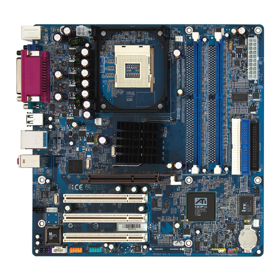
Then follow these steps designed to guide you through a quick and correct installation of your system. 3.1 Step-by-Step Installation Accessories Of MT63 ATI Rs300 Chipset Socket 478 CPU Fan Connector - FAN1... -
Page 16: Step 1 Cpu Installation
Step 1 CPU Installation: This mainboard supports Intel Pentium 4/Celeron Socket 478 series CPU. Please follow the steps as follows to finish CPU installation. Note the CPU orientation when you plug it into CPU socket. 1. Pull up the CPU socket lever to 90-degree angle. CPU socket lever up to 90-degree angle 2. -
Page 17: Step 2 Set Jumpers
Step 2. Set Jumpers This mainboard is jumperless! The default jumper settings have been set for the common usage standard of this mainboard. Therefore, you do not need to reset the jumpers unless you require special adjustments as any of the following cases: 1. -
Page 18: Step 4 Install Internal Peripherals In System Case
Step 4 Install Internal Peripherals in System Case Before you install and connect the mainboard into your system case, we rec- ommend that you first assemble all the internal peripheral devices into the com- puter housing, including but not limited to the hard disk drive (IDE/HDD), floppy disk drive (FDD), CD-ROM drive, and ATX power supply unit. -
Page 19: Step 5 Mount The Mainboard On The Computer Chassis
Step 5 Mount the Mainboard on the Computer Chassis 1. You may find that there are a lot of different mounting hole positions both on your computer chassis and on the mainboard. To choose correct mounting holes, the key point is to keep the back-panel of the mainboard in a close fit with your system case, as shown below. -
Page 20: Step 6 Connect Front-Panel Switches/Leds/Speaker Connectors
Step 6 Connect Front-Panel Switches/LEDs/Speaker connectors You can find there are several different cables already existing in the system case and originating from the computer's front-panel devices (HDD LED, Power LED, Reset Switch or PC Speaker etc.) These cables serve to connect the front- panel switches and LEDs to the mainboard's front-panel connectors group (JP 2), as shown below. -
Page 21: Step 7 Connect Ide, Floppy, And Serial Ata Disk Drives
Step 7 Connect IDE, Floppy, and Serial ATA Disk Drives 1. IDE cable connectors 2. Floppy cable connector 3. Serial ATA connectors (Optional) ATA1 Serial ATA - 17 -... -
Page 22: Step 8 Connect Other Internal Peripherals
Step 8 Connect Other Internal Peripherals 1. CD_IN Header (J4) (black) CD_IN Header (J6) (white) Auxiliary CD in Header (J5)(white) J4 (black) J6 (white) J5 (white) 2. SPDIF In/Out Header (JP4) 3. Front Audio Header (JP3) - 18 -... -
Page 23: Step 9 Connect Power Supply
4. USB Header (J2) 5. IR Header (J3) IR (J3) Step 9 Connect the Power Supply 1. System power connector (ATX1/ATX2) ATX12V ATX1 - 19 -... -
Page 24: Step 10 Install Add-On Cards In Expansion Slots
Step 10 Install Add-on Cards in Expansion Slots 1. Accelerated Graphics Port (AGP) Card AGP proof LED: Serving as a smrt burn-out protection for the motherboard, this red LED lights up if you plug in any 3.3V AGP card into the AGP slot. When this LED is Lit, there is no way you can turn on the system power even if you press the power button. -
Page 25: Step 11 Connect External Peripherals To Back-Panel
Step 11 Connect External Peripherals to Back-Panel You are now ready to put the computer case back together and get on to the external peripherals connections to your system's back-panel. PS/2 mouse Port PS/2 keyboard Port Parallel port (DB25 female) VGA Port (DB15 female) Serial Port (DB9 male) 4 USB 2.0/1.1 (0/1) (Universal Serial Bus) Ports... -
Page 26: Step 12 First Time System Boot Up
Step 12 First Time System Boot Up To assure the completeness and correctness of your system installation, you may check the above installation steps once again before you boot up your system for the first time. 1. Insert a bootable system floppy disk (DOS 6.2x, Windows 95/98/NT, or others) which contains FDISK and FORMAT utilities into the FDD. -
Page 27: Step 13 Install Driver & Software Components
2000/ME/XP/NT operating systems only. Make sure your operating system is already installed before running the drivers installation CD-ROM programs. 1. Insert the MT63 bundled CD-ROM into your CD-ROM drive. The autorun program will display the drivers main installation window on screen. -
Page 28: Jumper Settings
3.2 Jumper Settings Several hardware settings are made through the use of jumper caps to connect jumper pins to the mainboard. Pin #1 could be located at any corner of each jumper; you just find a location marked with a while right angle, which stands for pin1#. -
Page 29: Jumpers & Connectors Guide
Jumpers & Connectors Guide Use the mainboard layout on page 11 to locate CPU socket, memory slots, expansion slots, jumpers and connectors on the mainboard during the installa- tion. The following list will help you to identify jumpers, slots, and connectors along with their assigned functions: B2~B4 B5~B6... -
Page 30: Jumpers
Jumpers : Clear CMOS setting Back Panel Connectors : PS/2 mouse Port : PS/2 keyboard Port PRN1 : Parallel port (DB25 female) VGA1 : VGA Port (DB15 female) COM1 : Serial Port (DB9 male) : 4 USB 2.0/1.1 (0/1) (Universal Serial Bus) Ports : LAN Port MIC_IN : Bass/Center-Out (Mic-In) Port... -
Page 31: Clear Cmos Setting (Jp1)
: CD_IN (black) Header : CD_IN (white) Header : Auxiliary CD in (white) Header : SPDIF In/Out Header : Front Audio Header : USB Header : IR Header Jumpers Clear CMOS Setting (JP1) JP1 is used to clear CMOS data. Clearing CMOS will result in the permanently erasing previous system configuration settings and the restoring original(factory- set) system settings. -
Page 32: Back-Panel Connectors Ps/2 Keyboard & Ps/2 Mouse Connectors
Back-Panel Connectors PS/2 Keyboard & PS/2 Mouse Connectors Two 6-pin female PS/2 keyboard & Mouse connectors are located at the rear panel of the mainboard. Depending on the computer housing you use (desk- top or tower), the PS/2 Mouse connector is situated at the top of the PS/2 Key- board connector when the main-board is laid into a desktop, as opposed to a tower where the PS/2 Mouse connector is located at the right of the PS/2 Keyboard's. -
Page 33: Usb Port Connectors
USB Port Connectors Four female connectors USB0/USB1 share the same USB(Universal Serial Bus)bracket at the rear panel of your USB Port 0/1/2/3 mainboard. Plug each USB device jack into an available USB0, 1, 2, 3 connector. LAN Port Connector This mainboard can accommodate one device on LAN. -
Page 34: Front-Panel Connectors Atx Power On/Off Switch Connector (Pwon)
Front-Panel Connectors ATX Power On/Off Switch Connector (PWON) The Power On/Off Switch is a momentary type switch used for turning on or off the system ATX power supply. Attach the connector cable from the Power Switch to the 2-pin (PWON) header on the mainboard. HLED Speaker Reset... -
Page 35: Green Led/Power Led Connector (Gled/Pled)
Green LED/Power LED Connector (GLED/PLED) This header is dual color LED function. Dual color LED function is defined by either Power LED or Green LED, the header can be in these states. The Green LED indicates that the system is currently in one of the power saving mode (Doze/Standby/Suspend). -
Page 36: Power Led Connector (Pled)
Power LED Connector (PLED) Attach the 3-pin Power-LED connector cable from the housing front-panel to the (PLED) header on the mainboard. The power LED stays light while the system is running. HLED Speaker Reset PLED PWON GLED Hardware Reset Connector (Reset) Attach the 2-pin hardware reset switch cable to the (Reset) header. -
Page 37: Internal Peripherals Connectors
Internal Peripherals Connectors Enhanced IDE, Floppy Connectors The mainboard features two 40-pin dual-channel IDE device connectors (IDE1/ IDE2) providing support for up to four IDE devices, such as CD-ROM and Hard Disk Drives (H.D.D.). This mainboard also includes one 34-pin floppy disk controller (FDC) to accommodate the Floppy Disk Drive (FDD1). -
Page 38: Other Connectors
Other Connectors ATX Power Supply Connectors (ATX1 and ATX2) This motherboard uses 20-pin (ATX2) Pentium 4 standard ATX power header, and ATX1 with 1X4-pin +12V PC ATX power supply headers. Please make sure you plug in the right direction. ATX12V ATX2 ATX1 ATX1... -
Page 39: Cpu, Chipset And System Fan Connectors (Fan1/2/3)
CPU, Chipset and System Fan Connectors - FAN1/2/3 The mainboard provides three onboard 12V cooling fan power connectors to support CPU (FAN1), Chipset (FAN2), or System (FAN3) cooling fans. FAN1 GND +12V FANIO1 FAN2 FAN3 Note : Both cable wiring and type of plug may vary , which depends on the fan maker. -
Page 40: Auxiliary Cd In Connector (J5)(White)
AUXILIARY CD in Connector (J5) (White) Port J5 can be used to connect a stereo audio input from CD-ROM, TV-tuner or MPEG card. 4 3 2 1 AUX_IN Right AUX_IN Left Pin Assignments (J5): 1=AUX_IN Right 2=GND 3=GND 4=AUX_IN Left J5 (white) SPDIF_Out/In Header (JP4) Port JP4 can be used to connect to a device with digital audio inputs/outputs. -
Page 41: Front-Panel Microphone And Line_Out Header (Jp3)
Front-Panel Microphone and Line_out Header (JP3) E7 E6 This header allows users to install auxiliary front-oriented microphone and line- out ports for easier access. Either the Mic and Line_out connector on back- panel or JP3 header are available at the same time. If you would like to use this JP3 header on front-panel, please remove all jumpers from JP3 and install your special Extra Mic / Line_out cable instead. -
Page 42: Irda Header (J3)
IrDA Header (J3) If you have an infrared device, this mainboard can implement IrDA tranfer func- tion. To enable the IrDA transfer function, follow these steps: Pin Assignment: IR (J3) 1=NC 2=KEY 3=VCC 4=GND 5=IRTX 6=IRRX Note : Before connect your IR device, please be sure each IR on board pin allocation is matchable with the pin of the IR device. -
Page 43: System Memory Configuration
3.3 System Memory Configuration The MT63 mainboard has two 184-pin DIMM slots that allow you to install from 64MB up to 2GB of system memory. Each 184-pin DIMM (Dual In-line Memory Module) Slot can accommodate 64MB, 128MB, 256MB, 512MB, and 1GB of PC1600/PC2100/PC2700/PC3200 compliant 2.5V single (1 Bank) or double (2 Bank) side 64-bit wide data path DDR SDRAM modules. -
Page 44: Software Utility
4 SOFTWARE UTILITY 4.1 Mainboard CD Overview Note : The CD contents attached in MT63 mainboard are subject to change without notice. To start your mainboard CD disc, just insert it into your CD-ROM drive and the CD AutoRun screen should appear. If the AutoRun screen does not appear, double click or run D:\Autorun.exe (assuming that your CD-ROM drive is... -
Page 45: Install Mainboard Software
Insert the attached CD into your CD-ROM drive and the CD AutoRun screen should appear. If the AutoRun screen does not appear, double click on Autorun icon in My Computer to bring up Shuttle Mainboard Software Setup screen. Select using your pointing device (e.g. mouse) on the "Install Mainboard Software"... -
Page 46: A Install Ati Chipset Driver
4.2.A Install ATI Chipset Driver Select using your pointing device (e.g. mouse) on the "Install ATI Chipset Driver" bar to install ATI chipset driver. Once you made your selection, a Setup window run the installation automati- cally. When the copying files is done, make sure you reboot the system to take the installation effect. -
Page 47: C Install Realtek Audio Driver
4.2.C Install Realtek Audio Driver Select using your pointing device (e.g. mouse) on the "Install Realtek Audio Driver" bar to install audio driver and AC'97 Sound System Software. Once you made your selection, a Setup window run the installation automati- cally. -
Page 48: E Install Silicon Raid Driver (Optional)
4.2.E Install Silicon RAID Driver (Optional) Select using your pointing device (e.g. mouse) on the "Install Silicon RAID Driver" bar to install SATA RAID driver. Important : Under Win 98/Me/2K/XP, please check the "Read me" file and follow steps for manual installation. 4.2.F Install ATI USB 2.0 Driver Select using your pointing device (e.g. -
Page 49: View The User's Manual
4.3 View the User's Manual Select using your pointing device (e.g. mouse) on the "Manual" bar. Click on the "Install Acrobat Reader" bar if you need to install it, or click on the "Manual" bar to view MT63 user's manual. - 45 -... -
Page 50: Bios Setup
5 BIOS SETUP MT63 BIOS ROM has a built-in Setup program that allows users to modify the basic system configuration. This information is stored in battery-backed RAM so that it retains the Setup information even if the system power is turned off. -
Page 51: The Main Menu
5.2 The Main Menu Once you enter the AwardBIOS(tm) CMOS Setup Utility, the Main Menu will appear on the screen. The Main Menu allows you to select from several setup functions and two exit choices. Use the arrow keys to select among the items and press <Enter> to accept and enter the sub-menu. - Page 52 PC Health Status This entry shows the current system temperature, Voltage, and FAN speed. Load Fail-Safe Defaults Use this menu to load the BIOS default values for the minimal/stable performance of your system to operate. Load Optimized Defaults Use this menu to load the BIOS default values that are factory-set for optimal performance system operation.
-
Page 53: Standard Cmos Features
Standard CMOS Features The items in Standard CMOS Setup Menu are divided into several categories. Each category includes no, one or more than one setup items. Use the arrow keys to highlight the item and then use the <PgUp> or <PgDn> keys to select the value you want in each item. Date <Month>... - Page 54 IDE Secondary Slave Options are in its sub-menu. Press <Enter> to enter the sub-menu of detailed options. Drive A Select the type of floppy disk drive installed in your system. Ø The choice: None, 360K, 5.25 in, 1.2M, 5.25 in, 720K, 3.5 in, 1.44M, 3.5 in, or 2.88M, 3.5 in.
- Page 55 IDE Primary Master Selecting 'manual' lets you set the remaining fields on this screen and select the type of fixed disk. "User Type" will let you select the number of cylinders, heads, etc., Note: PRECOMP=65535 means NONE ! Ø The choice: None, Auto, or Manual. Access Mode Choose the access mode for this hard disk.
-
Page 56: Advanced Bios Features
Advanced BIOS Features This section allows you to configure your system for basic operation. You have the opportunity to select the system's default speed, boot-up sequence, keyboard operation, shadowing, and security. CPU Feature Option are in its sub-menu. Press<Enter>to enter the sub-menu of detailed options. Thermal Management Use these items to set the Thermal Management. - Page 57 Bios Write Protect This item allows you to enable or disable the Bios Write Protect. If you want to flash BIOS, you must set it Disabled. Ø The choice: Enabled or Disabled. Virus Warning Allows you to choose the VIRUS Warning feature for IDE Hard Disk boot sector protection.
- Page 58 Boot Other Device If BIOS can't load O.S. from First/Second/Third boot device you select above, BIOS will search other devices and attempt to load O.S.. Ø The choice: Enabled or Disabled. Swap Floppy Drive If you have two floppy diskette drives in your system, this item allows you to swap the assigned drive letters so that drive A becomes drive B, and drive B becomes drive A.
- Page 59 Security Option Select whether the password is required every time the system boots or only when you enter setup. System The system will not boot and access to Setup will be denied if the correct password is not entered promptly. Setup The system will boot, but access to Setup will be denied if the correct password is not entered promptly.
-
Page 60: Advanced Chipset Features
Advanced Chipset Features This section allows you to configure the system based on the specific features of the installed chipset. This chipset manages bus speeds and access to sys- tem memory resources, such as DRAM and the external cache. It states that these items should never need to be altered. - Page 61 VDIMM Voltage This item allows you to set VDIMM Voltage. Ø The Choice: Auto, 2.65V, 2.70V, 2.75V. Note: Over voltage may damage DDR module. VAGP Voltage This item allows you to set VAGP Voltage. Ø The Choice: Auto, 1.6V, 1.65V, 1.7V. Note: Over voltage may damage AGP Card.
- Page 62 CAS Latency Time When synchronous DRAM is installed, the number of clock cycles of CAS latency depends on the DRAM timing. Don't change this field from the default value specified by the system designer. Ø The Choice: 1, 1.5, 2, 2.5, 3, 3.5 or 4. DRAM RAS# to CAS# Delay This field lets you insert a timing delay between the CAS and RAS strobe signals, and you can use it when DRAM is written to, read from, or re-...
- Page 63 Spectrum Spreading Amount This item allows you to set the spectrum spreading amount. Ø The Choice : 0.25%, 0.50%, 0.75%, 1.00%, 1.25%, 1.50%, 1.75%, or Disabled. ** On-Chip VGA Setting ** AGP Aperture Size This item defines the size of the aperture if you use an AGP graphics adapter.
-
Page 64: Integrated Peripherals
Integrated Peripherals South OnChip IDE Device Option are in its sub-menu. Press<Enter>to enter the sub-menu of detailed options. IDE DMA transfer access Internal PCI/IDE field, above, is Disabled. Ø The choice: Enabled or Disabled. OnChip IDE Channel 0/1 Use these items to enable or disable the PCI IDE channels that are integrated on the mainboard. - Page 65 Primary/Secondary Master/Slave UDMA If you install a device that supports UltraDMA that provides faster access to IDE devices, change the item to Auto. Ø The choice: Disabled or Auto. South OnChip PCI Device Option are in its sub-menu. Press<Enter>to enter the sub-menu of detailed options. Onboard AC97 Audio This item allows you to control the onboard AC97 Audio.
- Page 66 Full-duplex means that you can transmit and send information simulta- neously. Half-duplex is the transmission of data in both directions, but only one direction at a time. Ø The choice: Full or Half. Onboard Parallel Port This item allows you to determine onboard parallel port controller I/O address and interrupt request ( IRQ ).
- Page 67 support Plug and Play. Ø The Choice:Disabled or Enabled. IDE HDD Block Mode The chipset contains a PCI IDE interface with support for two IDE channels. Select enabled to activate the primary and/or secondary IDE interface. Select disabled to de-activate this interface, in case that you install a primary and/or secondary add-in IDE interface.
-
Page 68: Power Management Setup
Power Management Setup The Power Management Setup allows you to configure your system to most effectively saving energy while operating in a manner consistent with your own style of computer use. ACPI Function This item allows you to enable/disable the Advanced Configuration and Power Management (ACPI). - Page 69 Suspend --> Off Monitor is blanked when the system enters into the suspend mode. Ø The choice: Always On or Suspend ->Off. Video Off Method This determines the manner in which the monitor is blanked. V/H SYNC+Blank This selection will cause the system to turn off the vertical and horizontal synchronization ports and write blanks to the video buffer.
- Page 70 PS2 Keyboard Power ON This item allows you to set the PS2 Keyboard Power On function Ø The choice: Disabled, Password, or Hot KEY. KB Power ON Password This item allows you to set the KB Power On Password. Ø Press" Enter" to set Password. Hot Key Power On This item allows you to set the Hot Key Power On.
-
Page 71: Pnp/Pci Configurations
PnP/PCI Configurations This section describes the configuration of PCI bus system. PCI or Personal Computer Interconnection is a system which allows I/O devices to operate at the speed CPU itself keeps when CPU communicating with its own special components. This section covers some very technical items, and it is strongly recommended that only experienced users should make any changes to the default settings. - Page 72 IRQ Resources When resources are controlled manually, assign each system interrupt a type, depending on the type of device using the interrupt. IRQ3/4/5/7/10/11/12/14/15 assigned This item allows you to determine the IRQ assigned to the ISA bus and is not available to any PCI slot. Legacy ISA for devices is compliant with the original PC AT bus specification;...
-
Page 73: Pc Health Status
PC Health Status Shutdown Temperature Select the combination of lower and upper limits for the system shutdown temperature, if your computer contains an environmental monitoring sys- tem. If the temperature extends beyond either limit, the system shuts down. Ø The choice: 60 C/140 F, 65 C /149... -
Page 74: Load Fail-Safe Defaults
Load Fail-Safe Defaults When you press <Enter> on this item, you will get a confirmation dialog box with a message similar to: Load Fail-Safe Defaults (Y/N) ? N Pressing 'Y' loads the BIOS default values for the most stable, minimal performance system operations. - Page 75 Set Supervisor/User Password Steps to set supervisor/user password are described as follows: New Password Setting: 1. While pressing <Enter> to set a password, a dialog box appears to ask you enter a password. 2. Key in a new password that can not exceed eight characters. 3.
-
Page 76: Save & Exit Setup
Save & Exit Setup Pressing <Enter> on this item asks for confirmation: Save to CMOS and EXIT (Y/N)? Y Pressing "Y" stores the selections made in the menus of CMOS - a special section of memory that stays on after you turn your system off. The next time you boot your computer, the BIOS configures your system according to the Setup selections stored in CMOS.
Need help?
Do you have a question about the MT63 and is the answer not in the manual?
Questions and answers