Table of Contents
Advertisement
Quick Links
Advertisement
Table of Contents

Related Manuals for Shuttle ME62


Summary of Contents for Shuttle ME62
- Page 1 ME62/ME63/ME64 Intel 810 Family Based Twin Processors Main Board User's Manual...
- Page 2 The information contained in this manual is provided for general use by the customers. Trademarks Spacewalker is a registered trademark of Shuttle Inc. Intel, Pentium is a registered trademarks of Intel Corporation. PC/ATX is a registered trademark of International Business Machines (IBM) Corporation.
-
Page 3: Table Of Contents
TABLE OF CONTENTS WHAT’S IN THE MANUAL ..............5 Quick Reference ....................5 About This Manual....................5 Technical Support ....................5 1 INTRODUCTION ................6 1.1 TO DIFFERENT USERS................6 First-Time DIY System Builder..............6 Experienced DIY User ................6 System Integrator .................. - Page 4 STEP 11 Connect External Peripherals to Back Panel ......23 STEP 12 First Time System Boot Up ............. 25 STEP 13 Install Drivers & Software Components ........26 3.2 JUMPER SETTINGS..................2 7 JUMPERS & CONNECTORS GUIDE ............ 28 Set PS/2 or USB Keyboard/Mouse Power-On Function (J1) ....30 ICH Voltage Setting (J25) ...............31 AMR Slot Setting (J9) ................31 Configuring CPU Host Clock (J10A, J26) ..........
- Page 5 Hardware Reset Connector (RST)............37 Speaker Connector (SPK) ..............37 PWR LED Connector (PWRLED) ............37 Front Panel USB Connector Header ............38 Line-Out and Mic-In Header ..............38 Enhanced IDE Ports and Floppy Connectors......... 38 ATX Power Supply Connector (JWR1)........... 39 Cooling Fan Connectors for CPU1 (FAN1), CPU2 (FAN2) &...
- Page 6 5 BIOS SETUP ................48 5.1 ENTERING BIOS..................4 8 5.2 THE MAIN MENU..................4 9 STANDARD CMOS FEATURES ..............51 ADVANCED BIOS FEATURES ..............55 ADVANCED CHIPSET FEATURES ............58 INTEGRATED PERIPHERALS ..............61 POWER MANAGEMENT SETUP ...............65 PNP/PCI CONFIGURATION...............69 PC HEALTH STATUS .................71 FREQUENCY/VOLTAGE CONTROL ............
-
Page 7: What's In The Manual
BIOS Setup >> How to Configure............Page 48 About This Manual For First-Time DIY System Builder............Page 6 For Experienced DIY User...............Page 6 For System Integrator................P age 6 Technical Support Contact Your Dealer Check Shuttle’s Web Site Shuttle’s (RMA or Warranty?) Policy - 5 -... -
Page 8: Introduction
Experienced DIY User Congratulations on your purchase of the Shuttle ME62/ME63/ME64 mainboard. You will find that installing your new Shuttle ME62/ME63/ME64 mainboard is just that easy. Bundled with an array of onboard functions, the highly-inte- grated ME62/ME63/ME64 mainboard provides you with a total solution to build the most stable and reliable system. -
Page 9: Item Checklist
1.2 Item Checklist Check all items you received with your ME62/ME63/ME64 mainboard to make sure nothing is missing. The complete package should include: One Shuttle ME62/ME63/ME64 Mainboard (with onboard Slot 1 and Socket 370, built-in Intel i810(E) chipset , MicroATX form factor,... -
Page 10: Features
2 FEATURES The ME62/ME63/ME64 mainboard is carefully designed for the demanding PC user who wants high performance and maximum intelligent features in a compact package. 2.1 Specifications CPU Support <Slot 1> Pentium III processors : 500 ~ 666+ MHz Pentium II processors : 233/66 ~ 333/66 and 350/100 ~ 500/100 MHz Celeron SEPP processors : 266 ~ 433+ MHz <Socket 370>... - Page 11 PCI Expansion Slots Provides three 32-bit PCI slots. UPT and AMR Expansion Slots Provides one UPT (USB-PanelLink-TV out) slots and featuring one AMR (Audio/Modem Riser) slot. LPC Super I/O Onboard Provides a variety of I/O interfaces: 1 × Floppy interface for 3.5-inch FDD with 720KB, 1.44MB, 2.88MB format.
- Page 12 Advanced Configuration and Power Interface Features four power savings modes: S1 (Power On Suspend), S3 (Suspend to RAM), S4 (Suspend to Disk), and S5 (Soft-Off). ACPI provides more efficient Energy Savings Features controlled by your operating system that supports OS Direct Power Management (OSPM) functionality. System BIOS Provides licensed Award BIOS V6.0 PG on Intel Firmware Hub with 4 Mb flash core (Intel 4Mb FWH).
-
Page 13: Hardware Installation
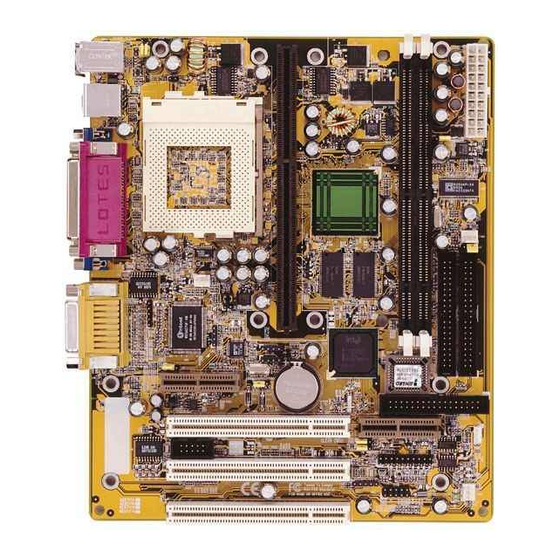
3 HARDWARE INSTALLATION This section outlines how to install and configure your ME62/ME63/ME64 mainboard. Refer to the following mainboard layout to help you identify various jumpers, connec- tors, slots, and ports. Then follow these steps designed to guide you through a quick and correct installation of your system. -
Page 14: Step 1 Install The Cpu
Step 1 Install the CPU: <The Installation of PPGA Celeron Processor> 1. Locate the CPU ZIF (Zero Insertion Force) socket on the upper-right sector of your mainboard (between the back-panel connectors and the DIMM memory banks). 2. Pull the CPU ZIF socket lever slightly sideways away from the socket to unlock the lever, then bring it to an upward vertical position. - Page 15 <The Installation of Pentium II/III Processor> 1. Mark your CPU Frequency Checking the working frequency of your cpu that should be clearly marked on the CPU cover or write your own combination in the space provided. Pentium II/III Processor Installation <Locate the Retention Mechanism>...
- Page 16 Celeron Processor Installation <Locate the Retention Mechanism> To install a CPU, first turn off your system and remove its cover. Insert two Retention Mechanism (3) on opposite side of Slot 1. Fix (3) by inserting Attach Mounts (4) up through holes (A1...A4) in the bottom of the mainboard, and screw the four captive nuts (3.1).
-
Page 17: Step 2 Set Jumpers
Step 2. Set Jumpers This mainboard is jumperless! The default jumper settings have been set for the common usage standard of this mainboard. Therefore, you do not need to reset the jumpers unless you require special adjustments as in any of the following cases: 1. -
Page 18: Step 4 Install Internal Peripherals In System Case
Step 4 Install Internal Peripherals in System Case Before you install and connect the mainboard into your system case, we recommend that you first assemble all the internal peripheral devices into the computer housing, including but not limited to the hard disk drive (IDE /HDD), floppy disk drive (FDD), CD-ROM drive, and ATX power supply unit. -
Page 19: Step 5 Mount The Mainboard On The Computer Chassis
Step 5 Mount the Mainboard on the Computer Chassis 1. You may find that there are a lot of different mounting hole positions both on your computer chassis and on the mainboard. To choose a correct mounting hole, the key point is to keep the back-panel of the mainboard in a close fit with your system case, as shown below. -
Page 20: Step 6 Connect Front Panel Switches/Leds/Speaker
Step 6 Connect Front Panel Switches/LEDs/Speaker/USB connectors You can find there are several different cables already existing in the system case and originating from the computer’s front-panel devices (HDD LED, Power LED, Reset Switch, PC Speaker or connectors for USB devices etc.) These cables serve to connect the front-panel switches, LEDs and USB connectors to the mainboard’s front-panel connectors group (J20 and JP11), as shown below. - Page 21 4. EPMI (Hardware System Management Interface) 5. Green_LED 6. PC Speaker 7. Hardware Reset Switch 8. Front panel USB connectors header 9. Line-Out and Mic-In header - 19 -...
-
Page 22: Step 7 Connect Ide & Floppy Disk Drives
Step 7 Connect IDE & Floppy Disk Drives 1. IDE cable connector 2. FDD cable connector Step 8 Connect Other Internal Peripherals 1. COM 2 cable connector - 20 -... -
Page 23: Step 9 Connect The Power Supply
2. CD_IN, AUX_IN, TAD_IN connector 3. SIR/CIR connector Step 9 Connect the Power Supply 1. System power connector - 21 -... -
Page 24: Step 10 Install Add-On Cards In Expansion Slots
Step 10 Install Add-on Cards in Expansion Slots 1. Audio Modem Riser (AMR) Card Note: You may purchase the optional. Modem Riser Card. 2. USB -PanelLink-TV out (UPT) Card Note: You may purchase the optional. CV11 : TV-Out Card. CV12 : Panel Link Card. CV14 : USB Hub Card. -
Page 25: Step 11 Connect External Peripherals To Back Panel
Step 11 Connect External Peripherals to Back Panel You are now ready to put the computer case back together and get on to the external peripherals connections to your system’s back-panel. PS/2 Mouse 1. PS/2 Mouse and Keyboard PS/2 keyboard USB1 2. - Page 26 5. VGA connector 6. Audio Line_in / Line_out / Mic_in Mic_in Line-In Line-Out 7. MIDI/Game Port MIDI/GAME Port - 24 -...
-
Page 27: Step 12 First Time System Boot Up
Step 12 First Time System Boot Up To assure the completeness and correctness of your system installation, you may check the above installation steps once again before you boot up your system for the first time. 1. Insert a bootable system floppy disk (DOS 6.2x, Windows 95/98/NT, or others) which contains FDISK and FORMAT utilities into the FDD. -
Page 28: Step 13 Install Drivers & Software Components
Make sure your Windows 9x operating system is already installed before running the drivers installation CD-ROM programs. 1. Insert the ME62/ME63/ME64 bundled CD-ROM into your CD-ROM drive. The auto-run program will display the drivers main installation window on screen. -
Page 29: Jumper Settings
3.2 Jumper Settings Several hardware settings are made through the use of jumper caps to connect jumper pins on the mainboard. Pin #1 is located on the top or on the left when holding the mainboard with the keyboard connector or other back-panel connectors opposite from you, as shown below. -
Page 30: Jumpers & Connectors Guide
Jumpers & Connectors Guide Use the mainboard layout on page 11 to locate CPU socket, memory banks, expansion slots, jumpers and connectors on the mainboard during the installation. The following list will help you identify jumpers, slots, and connectors along with their assigned functions: CPU/Memory/Expansion Slots Slot 1 : CPU Socket for Slot 1 Pentium II/III processors... - Page 31 : VGA Port (DB15 female) PRINTER : Parallel Port (DB25 female) LINE-OUT : Line-Out Port LINE-IN : Line-In Port MIC-IN : Mic-In Port GAME/MIDI : MIDI/Game Port Front Panel Connectors (J20, JP11 and JP15) PWON : ATX Power On/Off Momentary Type Switch GLED : Green LED (ON when system in power savings mode) EPMI...
-
Page 32: Set Ps/2 Or Usb Keyboard/Mouse Power-On Function (J1)
Set PS/2 or USB Keyboard/ Mouse Power-On Function (J1) ME62/ME63/ME64 mainboard provides an easy power-on function by PS/2 Keyboard/Mouse or USB Keyboard/Mouse. Note: When you enable Keyboard Power-On, you also need to configure the proper hot-key combination <Ctrl> + <function key F1 ~ F12>... -
Page 33: Ich Voltage Setting (J25)
ICH Voltage Setting (J25) This jumper allows you to select the voltage supplied to the Intel 82801AA (ICH). The default voltage should be used unless some IDE devices need more voltage supplied. Pin 1-2 (3.3V) default Pin 2-3 (3.9V) AMR Slot Setting (J9) The slot supports a specially designed audio and/or modem card called an AMR. -
Page 34: Configuring Cpu Host Clock (J10A, J26)
Configuring CPU Host Clock (J10A, J26) ME62/ME63/ME64 provide jumper J10A and J26 to set CPU host clock auto-detect by system BIOS or hardware configure the CPU host clock to 66MHz, 100MHz or 133MHz manually for over-clocking your 66MHz- based processor up to 100MHz, or over-clocking your 100MHz-based processor up to 133MHz. -
Page 35: Clear Cmos (J12)
Clear CMOS (J12) J12 is used to clear CMOS data. Clearing CMOS will result in permanently erasing the previous system configuration settings and restoring the original (factory-set) system settings. Pin 1-2 (Default) Pin 2-3 (Clear CMOS) Step 1. Turn off the system power (PC-> Off) Step 2. -
Page 36: Factory Reserved (J27)
Factory Reserved (J27) Open (Default) PS/2 Keyboard & PS/2 Mouse Connectors Two 6-pin female PS/2 keyboard & Mouse connectors are located at the rear panel PS/2 Mouse of the mainboard. Depending on the com- puter housing you use (desktop or minitower), the PS/2 Mouse connector is situated at the top of the PS/2 Keyboard connector when the mainboard is laid into... -
Page 37: Vga Connector
VGA Connector One 15-pin VGA connector is located at the rear panel of the mainboard. Parallel Port Connector One DB25 female parallel connector is located at the rear panel of the mainboard. Plug the connection cable from your par- allel device (printer, scanner, etc.) into this Parallel Port connector. -
Page 38: Midi/Game Port
MIDI/GAME Port The MIDI/GAME port is a 15-pin female connector. This port can be connected to any IBM PC compatible game with a 15- MIDI/GAME Port pin D-sub connector. MIDI Instrument Connection You will need a MIDI adapter to connect a MIDI compatible instru- ment to the sound card. -
Page 39: Epmi Connector (Epmi)
EPMI Connector (EPMI) Hardware System Management Interface (EPMI) header may attach to a 2-pin mo- mentary switch. Press the EPMI switch to force the system into power savings mode; press again to resume normal operation. HDD LED Connector (IDE LED) Attach the connector cable from the IDE device LED to the 2-pin HDD LED header. -
Page 40: Front Panel Usb Connector Header
Mic-In on back panel. Enhanced IDE Ports and Floppy Connector The ME62/ME63/ME64 mainboard features two 40-pin dual-channel IDE device connectors (IDE1/IDE0) providing support for up to four IDE devices, such as CD-ROM and Hard Disk Drives (H.D.D.). This mainboard also includes one 34-pin floppy disk controller (FDC) to accommodate the Floppy Disk Drive (F.D.D.). -
Page 41: Atx Power Supply Connector (Jwr1)
ATX Power Supply Connector (JWR1) Locate the 20-pin male header ATX power connector (JWR1) on your mainboard. Plug the power cable from the ATX power supply unit directly into JWR1 ATX power supply connector. Note 1: The ATX power connector is directional and will not go in unless the guides match perfectly making sure that pin#1 is properly positioned. -
Page 42: Com2 Connector
COM2 Connector Pin Assignments: 1=DCD- 2=RX 3=TX 4=DTR- 5=Ground 6=DSR- 7=RTS- 8=CTS- 9=RI- 10=NC SIR/CIR Connector (J13) If you have an Infrared device, this mainboard can implement SIR (Standard IR) and CIR (Cirsumer IR) transfer function. To enable the IR transfer func- tion, follow these steps: SIR Pin Assignments: 1=VCC 2=VCC 3=IRRX... -
Page 43: Audio Connector Aux_In (Jp2)
3=Ground 4=AUX_R Audio Connector TAD _In (JP4) Port JP4 can be used to connect a mo- dem audio line to ME62/ME63/ME64 mainboard. Typically, you would use this connector when running the voice mail software on your system for audio input and output. -
Page 44: System Memory Configuration
3.3 System Memory Configuration The ME62/ME63/ME64 mainboard has two 168-pin DIMM sockets that allow you to install from 16MB up to 512MB of system memory with SDRAM (Synchronous DRAM). Each DIMM (Dual In-line Memory Module) socket can accommodate 16MB, 32MB, 64MB, 128MB, and 256MB 3.3V single or double side SDRAM modules. -
Page 45: Software Utility
Install Audio Device Software - Installing onboard AD1881 CODEC audio driver. Manual - ME62/ME63/ME64 series mainboard user's manual in PDF format. Link to Shuttle Homepage - Link to shuttle website homepage. Browse this CD - Allows you to see the contents of this CD. -
Page 46: Install Inf Driver
Insert the attachment CD into your CD-ROM drive and the CD AutoRun screen should appear. If the AutoRun screen does not appear, double click on Autorun icon in My Computer to bring up Shuttle Mainboard Software Setup screen. Select using your pointing device (e.g. mouse) on the “Install Mainboard Software”... -
Page 47: Install Display Adaptor Driver Software
Insert the attachment CD into your CD-ROM drive and the CD AutoRun screen should appear. If the AutoRun screen does not appear, double click on Autorun icon in My Computer to bring up Shuttle Mainboard Software Setup screen. Select using your pointing device (e.g. mouse) on the “Install Display Adap- tor Driver Software”... -
Page 48: Install Audio Device Software
Insert the attachment CD into your CD-ROM drive and the CD AutoRun screen should appear. If the AutoRun screen does not appear, double click on Autorun icon in My Computer to bring up Shuttle Mainboard Software Setup screen. Select using your pointing device (e.g. mouse) on the “Install Audio Device Software”... -
Page 49: To View The User's Manual
Insert the attachment CD into your CD-ROM drive and the CD AutoRun screen should appear. If the AutoRun screen does not appear, double click on Autorun icon in My Computer to bring up Shuttle Mainboard Software Setup screen. Select using your pointing device (e.g. mouse) on the “Manual” bar. -
Page 50: Bios Setup
5 BIOS SETUP ME62/ME63/ME64 BIOS ROM has a built-in Setup program that allows users to modify the basic system configuration. This information is stored in battery-backed RAM so that it retains the Setup information even if the system power is turned off. -
Page 51: The Main Menu
5.2 The Main Menu Once you enter the AwardBIOS(tm) CMOS Setup Utility, the Main Menu will appear on the screen. The Main Menu allows you to select from several setup functions and two exit choices. Use the arrow keys to select among the items and press <Enter> to accept and enter the sub-menu. - Page 52 Integrated Peripherals Use this menu to specify your settings for integrated peripherals. Power Management Setup Use this menu to specify your settings for power management. PnP / PCI Configuration This entry appears if your system supports PnP / PCI. PC Health Status This entry shows the current system temperature, Voltage and FAN speed.
-
Page 53: Standard Cmos Features
Standard CMOS Features The items in Standard CMOS Setup Menu are divided into 10 catego- ries. Each category includes no, one or more than one setup items. Use the arrow keys to highlight the item and then use the <PgUp> or <PgDn>... - Page 54 IDE Secondary Master Options are in its sub menu. Press <Enter> to enter the sub menu of detailed options. IDE Secondary Slave Options are in its sub menu. Press <Enter> to enter the sub menu of detailed options. Drive A/Drive B Select the type of floppy disk drive installed in your system.
- Page 55 ****************************************************** IDE Adapters The IDE adapters control the hard disk drive. Use a separate sub menu to configure each hard disk drive. IDE HDD Auto-detection Press Enter to auto-detect the HDD on this channel. If detection is successful, it fills the remaining fields on this menu. Press Enter IDE Primary Master Selecting 'manual' lets you set the remaining fields on this screen.
- Page 56 Precomp Warning: Setting a value of 65535 means no hard disk. Min = 0, Max = 65535 Landing zone Set the Landing zone size. Min = 0, Max = 65535 Sector Number of sectors per track. Min = 0, Max = 255 ****************************************************** - 54 -...
-
Page 57: Advanced Bios Features
Advanced BIOS Features This section allows you to configure your system for basic operation. You have the opportunity to select the system's default speed, boot-up sequence, keyboard operation, shadowing and security. Virus Warning Allows you to choose the VIRUS Warning feature for IDE Hard Disk boot sector protection. - Page 58 First/Second/Third/Other Boot Device The BIOS attempts to load the operating system from the devices in the sequence selected in these items. The Choice: Floppy, LS/ZIF, HDD, SCSI, CDROM, LAN, Disabled. Swap Floppy Drive If the system has two floppy drives, you can swap the logical drive name assignments.
- Page 59 Security Option Select whether the password is required every time the system boots or only when you enter setup. System The system will not boot and access to Setup will be denied if the correct password is not entered at the prompt.
-
Page 60: Advanced Chipset Features
Advanced Chipset Features This section allows you to configure the system based on the specific features of the installed chipset. This chipset manages bus speeds and access to system memory resources, such as DRAM and the external cache. It also coordinates communications between the conventional ISA bus and the PCI bus. - Page 61 SDRAM Cycle Time Tras/Trc Select the number of SCLKs for an access cycle. The Choice: 5/7, 6/8. SDRAM RAS-to-CAS Delay This field lets you insert a timing delay between the CAS and RAS strobe signals, used when DRAM is written to, read from, or refreshed. Fast gives faster performance;...
- Page 62 Delayed Transaction The chipset has an embedded 32-bit posted write buffer to support delay transactions cycles. Select Enabled to support compliance with PCI specification version 2.1. The Choice: Enabled, Disabled. On-Chip Video Window Size Select the on-chip video window size for VGA drive use. The Choice: 32MB, 64MB, Disabled.
-
Page 63: Integrated Peripherals
Integrated Peripherals OnChip Primary/Secondary PCI IDE The integrated peripheral controller contains an IDE interface with support for two IDE channels. Select Enabled to activate each channel separately. The choice: Enabled, Disabled. IDE Primary/Secondary Master/Slave PIO The four IDE PIO (Programmed Input/Output) fields let you set a PIO mode (0-4) for each of the four IDE devices that the onboard IDE interface supports. - Page 64 USB Controller Select Enabled if your system contains a Universal Serial Bus (USB) controller and you have USB peripherals. The choice: Enabled, Disabled. USB Keyboard Support Select Enabled if your system contains a Universal Serial Bus (USB) controller and you have a USB keyboard. The choice: Enabled, Disabled.
- Page 65 Onboard FDC Controller This item specifices onboard floppy disk drive controller. This setting allows you to connect your floppy disk drives to the onboard floppy connector. Choose the "Disabled" settings if you have a separate control card. The choice: Enabled, Disabled. Onboard Serial Port1/Port2 This item is used to define onboard serial port 1 / port 2 to 3F8/IRQ4, 2F8/IRQ3.
- Page 66 EPP Mode Select This item select the EPP Mode, EPP 1.9 or EPP 1.7. ECP Mode Use DMA This item specifies DMA (Direct Memory Access) channel when ECP device is in use. The options are DMA 1 and DMA 3. This item will not show up when SPP and EPP printer mode is selected.
-
Page 67: Power Management Setup
Power Management Setup The Power Management Setup allows you to configure you system to most effectively save energy while operating in a manner consistent with your own style of computer use. ACPI Function This item allows you to enable/disable the Advanced Configuration and Power Management (ACPI). - Page 68 Max. Power Saving Maximum power management -- ONLY AVAILABLE FOR SL CPU's. Doze Mode = 1 min. Standby Mode = 1 min. Suspend Mode = 1 min. HDD Power Down = 1 min. User Defined Allows you to set each mode individually. When not disabled, each of the ranges are from 1 min.
- Page 69 This item determine the system will resume by activity of LAN. If enabled this feature system will power-on itself from power off when the activity of LAN. Note ME62/ME63 /ME64 support Wake-ON-LAN function with Intel LAN card only. The choice: Enabled, Disabled. CPU Thermal-Throttling Select the CPU Therma-Throttling rate.
- Page 70 Date (of Month) Alarm This item select the alarm date. Key in a DEC number: Min=0, Max=31. Time (hh : mm : ss) Alarm This item select the alarm time. *** Reload Global Timer Events *** If any of these items is set to Disabled, that system activity event will not be monitored to reload global timer.
-
Page 71: Pnp/Pci Configuration
PnP/PCI Configuration This section describes configuring the PCI bus system. PCI, or Personal Computer Interconnect, is a system which allows I/O devices to operate at speeds nearing the speed the CPU itself uses when communicating with its own special components. This section covers some very technical items and it is strongly recommended that only experienced users should make any changes to the default settings. - Page 72 If you set this field to "manual" choose specific resources by going into each of the sub menu that follows this field (a sub menu is pre- ceded by a ">"). The choice: Auto(ESCD), Manual. IRQ Resources When resources are controlled manually, assign each system interrupt a type, depending on the type of device using the interrupt.
-
Page 73: Pc Health Status
PC Health Status CPU Warning Temperature Since the mainboard support CPU temperature monitoring and over- hear alert. This item allows the user to set the threshold of CPU warning temperature. When CPU temperature over the threshold, system will slow down clock to prevent CPU damage. The choice: Disabled, 50°C/122°F, 53°C/127°F, 56°C/133°F, 60°C/140°F, 63°C/145°F, 66°C/151°F, 70°C/158°F. - Page 74 IN0(V) ~ IN2(V), +5V ~ -5V The mainboard support CPU and mainboard voltages monitoring. The onboard hardware monitor is able to detect the voltages output of the voltage regulators and power supply. VBAT(V) Battery voltage. 5VSB(V) 5V standby voltage by MicroATX power. Shutdown Temperature Select the combination of lower and upper limits for the system shut- down temperature, if your computer contains an environmental moni-...
-
Page 75: Frequency/Voltage Control
Frequency/Voltage Control Auto Detect DIMM/PCI Clk This item allows you to enable/disable auto detect DIMM/PCI Clock. The choice: Enabled, Disabled. Spread Spectrum This item allows you to enable/disable the spread spectrum modulate. The choice: Disabled, 0.25%(Center), 0.5%(Down). CPU Host/SDRAM Clock The choice: Default, 66/100MHz, 70/109MHz, 72/112MHz, 75/105MHz, 100/100MHz, 105/109MHz, 109/112MHz, 112/105MHz, 133/100MHz, 140/150MHz, 124/124MHz,... -
Page 76: Load Fail-Safe Defaults
Load Fail-Safe Defaults When you press <Enter> on this item you get a confirmation dialog box with a message similar to: Load Fail-Safe Defaults (Y/N) ? N Pressing 'Y' loads the BIOS default values for the most stable, minimal-performance system operations. Load Optimized Defaults When you press <Enter>... -
Page 77: Set Supervisor Password
Supervisor/User Password Setting You can set either supervisor or user password, or both of then. The differences between are: Supervisor Password and User Password The options on the Password screen menu make it possible to restrict access to the Setup program by enabling you to set passwords for two different access modes: Supervisor mode and User mode. - Page 78 Password Disable If you select System at Security Option of BIOS Features Setup Menu, you will be prompted for the password every time the system is rebooted or any time you try to enter Setup. If you select Setup at Security Option of BIOS Features Setup Menu, you will be prompted only when you try to enter Setup.
-
Page 79: Save & Exit Setup
Save & Exit Setup Pressing <Enter> on this item asks for confirmation: Save to CMOS and EXIT (Y/N)? Y Pressing "Y" stores the selections made in the menus in CMOS - a special section of memory that stays on after you turn your system off. The next time you boot your computer, the BIOS configures your system according to the Setup selections stored in CMOS.
Need help?
Do you have a question about the ME62 and is the answer not in the manual?
Questions and answers