Permobil F3 Corpus User Manual
Hide thumbs
Also See for F3 Corpus:
- Owner's manual (178 pages) ,
- User manual (78 pages) ,
- Assembly instruction manual (26 pages)
Table of Contents
Advertisement
Quick Links
Advertisement
Chapters
Table of Contents
Troubleshooting

Related Manuals for Permobil F3 Corpus


Summary of Contents for Permobil F3 Corpus
- Page 1 User manual British English F3 Corpus...
- Page 3 Dear Permobil User, We congratulate you on your choice of powered wheelchair. Our goal is for you to continue to feel satisfied with your choice of both vendor and product. Your powered wheelchair is designed to provide the highest possible comfort and safety while meeting both safety and environmental requirements.
- Page 4 Text Produced and published by Permobil Edition: 12 Date: 2019-09-03 Order no: 334968 eng-UK...
- Page 5 Regus 6th floor 2 Kingdom Street E-mail: info@permobil.uk Paddington W2 6BD London United Kingdom Head office of the Permobil Group Permobil AB Box 120 861 23 Timrå Sweden +46 60 59 59 00 Tel.: Fax: +46 60 57 52 50 E-mail: info@permobil.com...
-
Page 7: Table Of Contents
F3 Corpus Contents Important information..........................11 Guarantee ............................12 Product approval ..........................13 Technical support..........................13 Cyber security ............................14 Reporting incidents ..........................14 Spare parts and accessories .........................15 Ordering documentation........................15 Scrapping and recycling ........................15 Safety instructions ............................17 Descriptions of admonitions........................18 Warnings and precautions ........................21 Getting to know your wheelchair ......................37 Overview............................39... - Page 8 Contents F3 Corpus Batteries ............................179 Transporting the wheelchair .......................185 Maintenance and repairs ........................197 Frequency of maintenance and inspection ....................201 Tool bag............................202 Cleaning ............................203 Battery replacement ..........................205 Batteries storage ..........................219 Wheels and tyres ..........................221 Main circuit breaker ..........................246 Brake release ...........................247 Positioning belt ..........................247...
- Page 9 F3 Corpus Contents Diagnostics R-Net LCD control panel....................261 Diagnostics R-Net LED control panel ....................265 Repairing defective units ........................270 Index ...............................271...
-
Page 11: Important Information
F3 Corpus Important information 1 Important information Before you begin using your wheelchair, it is important that you read and understand the content of these operating instructions, and in particular the safety instructions. These operating instructions are primarily intended to acquaint you with the functions and characteristics of the wheelchair and how to use them in the best manner possible. -
Page 12: Guarantee
NOTICE Unapproved replacement of parts If any part is replaced without approval from Permobil, the wheelchair guarantee will become invalid. Permobil accepts no liability for any loss that occurs as a result of a control system component being opened,... -
Page 13: Product Approval
• ISO 7176-21 • ISO 7176-25 Technical support In the event of technical problems, contact Permobil. Be prepared to provide the wheelchair serial number, located on the chassis, to ensure proper support. See 5.10 Serial number labels , Page 248. -
Page 14: Cyber Security
This is usually the same person you were in contact with at the time of purchase. To get in touch with your contact, use the link at www.permobil.com. Open your country page and the contact page. The page provides the necessary contact information and a document to help you provide us with the information we need to investigate the incident. -
Page 15: Spare Parts And Accessories
The expected service life of this product is five years. Ordering documentation Should you need another copy of this manual, you may order one from Permobil. Ask for the order number specified on the back cover. Scrapping and recycling Contact Permobil for information about the scrapping agreements in... - Page 16 F3 Corpus Important information...
-
Page 17: Safety Instructions
User’s Manual and all manuals supplied carefully, in particular the safety instructions and their warning texts. Permobil is not responsible for personal injuries or property damage resulting from failure to follow the warnings and instructions in this manual. -
Page 18: Descriptions Of Admonitions
F3 Corpus Safety instructions It is also of the utmost importance that you devote sufficient time to familiarising yourself with the various buttons, functions, steering controls, seat adjustment options and more offered by your wheelchair and its accessories before you begin using it. - Page 19 F3 Corpus Safety instructions WARNING! Warning admonition Indicates a hazardous situation which, if not avoided, could result in serious injury or death as well as damage to the product or other property. CAUTION! Caution admonition Indicates a hazardous situation which, if not avoided, could result in minor or moderate injury as well as damage to the product or other property.
- Page 20 F3 Corpus Safety instructions Provides information about the conditions or circumstances under which the information given applies.
-
Page 21: Warnings And Precautions
CAUTION! Operation Operation, driving If the wheelchair is equipped with lights, Permobil recommends Do not drive the wheelchair over any curbs or obstacles higher their use whenever you drive near public rights of way. Use than specified in the technical specifications section of the extreme caution when driving near unprotected edges, drops manual. - Page 22 F3 Corpus Safety instructions CAUTION! CAUTION! Operation, adjust seating system for Operation, pulling and minor impacts elevations Do not use the wheelchair to pull any kind of object and never Be sure to adjust the position of your seating according to the hang excessive weights on the backrest.
- Page 23 F3 Corpus Safety instructions CAUTION! WARNING! Operation Modifications Do not let children drive the wheelchair without supervision. Do Do not modify your wheelchair or any of its components. Your not drive the wheelchair on public streets or roads. Obey all...
- Page 24 Permobil recommends the use of securely fastened positioning belts at all times. When driving up a slope, try to keep moving at a steady speed.
- Page 25 F3 Corpus Safety instructions WARNING! WARNING! Operation - turning Operation - inclines Do not drive the wheelchair where the sideways gradient is Turning your wheelchair at high speeds may cause it to topple greater than that set forth in the technical specifications section with personal injury as a result.
- Page 26 F3 Corpus Safety instructions CAUTION! WARNING! Driving range Passengers The driving range stated in the technical specifications of this The wheelchair is not intended to carry passengers, regardless manual represents the theoretical driving range when testing the of the age of the passenger. The maximum user weight for your seating system is stated in the technical specifications section of wheelchair according to EN 12184 and ISO 7176-4.
- Page 27 If there is any sign of damage or wear on any positioning belt or aids, contact Permobil for a replacement • Elevation of the seat. immediately.
- Page 28 Before transportation, check that the wheelchair is properly secured and that both wheel locks are engaged. Secure the Permobil recommends that users transfer in the presence of or wheelchair front and rear to the vehicle at the tie-down points with the assistance of an attendant.
- Page 29 • The locking system must be dimensioned for the total weight of the wheelchair. You must inform Permobil as soon as possible after the event if • The user must use a three-point seat belt attached to the the wheelchair and its accessories have suffered damage during transport, damage during driving or damage from other vehicle.
- Page 30 F3 Corpus Safety instructions WARNING! CAUTION! Positioning belts and aids are not Driving in extreme weather conditions vehicle seatbelts Our wheelchairs are designed to withstand most adverse The wheelchair positioning belt and aids are designed to weather conditions. However, to minimise the risk of being...
- Page 31 If any of the covers or the joystick boot has cracks or tears, it Permobil. Incorrect settings may result in unsafe operation of the must be replaced immediately. Failure to do so may allow wheelchair and cause it to become unstable or uncontrollable.
- Page 32 F3 Corpus Safety instructions CAUTION! WARNING! Non-approved electrical or electronic Charging batteries devices Charge batteries in a well-ventilated room, not in a wardrobe Connecting non-approved electrical or electronic devices to the or cupboard. Batteries must not be charged in a bathroom or wheelchair’s electrical system may cause damage to the...
- Page 33 NOTICE overload. If any of these circuits stops working, stop using the Changing tyres wheelchair immediately and consult an authorised Permobil distributor. Avoid the use of sharp-edged tools when working with tyres. Any attempt to modify the safety circuits will result in unsafe wheelchair operation and may cause the chair to become unstable or uncontrollable.
- Page 34 If you are unsure how your wheelchair and its accessories EMC requirements should be properly stored, contact your supplier or Permobil for The electronics in a powered wheelchair can be affected by more information. external electromagnetic fields (e. g. from mobile phones).
- Page 35 Extraordinary events like these can lead to significant damage that is impossible to detect upon inspection. Damage caused by these types of incidents exceeds the limits covered by the manufacturer’s guarantee. For further information, contact Permobil AB to get in touch with a technical service supervisor.
- Page 36 F3 Corpus Safety instructions...
-
Page 37: Getting To Know Your Wheelchair
F3 Corpus Getting to know your wheelchair 3 Getting to know your wheelchair Overview............................39 Technical specifications........................40 3.2.1 Dimensions and weight........................41 3.2.2 Performance ............................43 3.2.3 Wheels..............................43 3.2.4 Electronics ............................44 3.2.5 Batteries ............................44 3.2.6 Control force ............................44 3.2.7 Circuit breakers ..........................44 3.2.8 Powered adjustable leg length ......................44... - Page 38 F3 Corpus Getting to know your wheelchair 3.4.2 Chassis..............................62 Control panel ..........................68 3.5.1 R-Net LCD control panel........................68 3.5.2 Joystick panel, R-Net LED control panel ....................115 3.5.3 ICS seat control panel ........................122 Accessories ..........................130...
-
Page 39: Overview
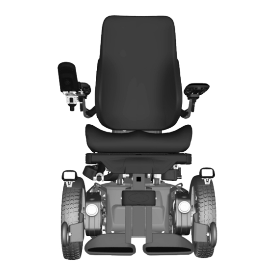
Getting to know your wheelchair Overview 1. Backrest 2. Control panel 3. Seat 4. Support wheel 5. Leg support 6. Footplates 7. Headrest 8. Armrest 9. Chassis 10. Serial number label 11. Castor wheels 12. Drive wheels Figure 1. F3 Corpus overview... -
Page 40: Technical Specifications
F3 Corpus Getting to know your wheelchair The F3 Corpus is a powered front-wheel drive wheelchair for outdoor and indoor driving. It is intended for people with physical disabilities. The wheelchair consists of a chassis and a seat. The chassis contains the wheelchair’s electronics, power supply and drive functions. -
Page 41: Dimensions And Weight
F3 Corpus Getting to know your wheelchair Length 1140 mm. Width 610 – 790 mm. Smallest transportation size Height 960 – 170 mm. Length 790 – 890 mm. Width 610 – 790 mm. Height 825 mm. 3.2.1 Dimensions and weight... - Page 42 F3 Corpus Getting to know your wheelchair Height 960 – 1170 mm Weight, including batteries 175 kg / 184 kg Minimum transport length 790 – 890 mm Minimum transport height 825 mm Minimum transport width 610 – 790 mm Seat plane angle 0°...
-
Page 43: Performance
F3 Corpus Getting to know your wheelchair 3.2.2 Performance Range 25 – 30 km Maximum speed forward 10 km/h 2.8 m Minimum braking distance from max. speed Hill-climbing ability 12° 6° Safe slope Static stability downhill 13° 17° Static stability uphill Static stability sideways 14°... -
Page 44: Electronics
F3 Corpus Getting to know your wheelchair 3.2.4 Electronics PM120 R-Net drive electronics type 3.2.5 Batteries Recommended battery type 24 cells, gel Battery capacity 2 x 60 Ah or 2 x 73 Ah, maintenance-free Charging time 8 hours Weight (2 x 60 Ah) -
Page 45: Labels
WARNING! Accident risk – Always replace missing labels Never remove a label from the wheelchair. If a label becomes difficult to read or falls off, order a replacement label from Permobil. 3.3.1 Read the instructions The label indicates that there are instructions that must be read and understood before use or adjustment. -
Page 46: Main Circuit Breaker Also Battery Isolator
F3 Corpus Getting to know your wheelchair 3.3.2 Main circuit breaker also battery isolator The label shows the power supply, Off or On. A description of the main circuit breaker function is found on page 246. Figure 3. Main circuit breaker also battery isolator. -
Page 47: Tie-Down Point
F3 Corpus Getting to know your wheelchair 3.3.4 Tie-down point The label indicates where the wheelchair must be secured during transportation. There is a label next to each tie-down point. A description of wheelchair transportation is found on page 185. -
Page 48: Warning
F3 Corpus Getting to know your wheelchair 3.3.7 Warning The label indicates that special attention is required. Exercise extreme caution where this warning symbol appears. Failure to observe warnings may lead to personal injury, including damage to the wheelchair and other property. -
Page 49: Battery Connections And Main Circuit Breaker
F3 Corpus Getting to know your wheelchair 3.3.8 Battery connections and main circuit breaker The labels show the polarity, which differs depending on which battery capacity, 60 Ah or 73 Ah, the product is equipped with. The positive battery cable (+) is shown in red on the label. -
Page 50: Design And Function
F3 Corpus Getting to know your wheelchair 3.3.9 Serial number label 1. Made in (country of final assembly) by (address of site of final assembly). 2. Serial number. 3. Product type. 4. Date of assembly. 5. EAN code. 6. Maximum user weight. - Page 51 F3 Corpus Getting to know your wheelchair Available functions may vary depending on the equipment fitted on your wheelchair. • seat lift • seat tilt • backrest recline • anterior tilt • leg support • powered adjustable leg length WARNING!
- Page 52 F3 Corpus Getting to know your wheelchair Powered seat lift A power-controlled seat lift allows stepless raising or lowering of the seat in order to adjust the height to tables, benches etc. When the seat lift is raised from the lowest position, the maximum speed of the wheelchair may be reduced.
- Page 53 F3 Corpus Getting to know your wheelchair The powered seat tilt control allows the preferred seat angle to be set within the operating range. WARNING! Tipping risk – driving with seat functions in use When operating the seat functions, the centre of gravity is also shifted, Figure 13.
- Page 54 F3 Corpus Getting to know your wheelchair Anterior tilt The following section only applies to wheelchairs equipped with anterior tilt. The anterior tilt function is only available on wheelchairs equipped with a powered seat lift and seat tilt. The anterior tilt function has programmable positions to meet individual needs.
- Page 55 F3 Corpus Getting to know your wheelchair WARNING! Anterior tilt Improper use of the anterior tilt feature on the wheelchair could cause the user to fall forward causing injury. Only use anterior tilt when recom- mended by a licensed clinical professional and/or ATP. Always use all positioning components on the wheelchair such as lap belts, chest straps, and knee blocks.
- Page 56 F3 Corpus Getting to know your wheelchair Powered backrest angle The backrest angle is adjustable (via the recline control), allowing the user to set a recline angle as needed within the operating range. WARNING! Risk of pinching while using seat functions There is a risk of crush-point accidents when using the powered seat functions.
- Page 57 F3 Corpus Getting to know your wheelchair Powered leg support angle The leg supports can be raised to the preferred angle within the operating range. Figure 16. Powered leg supports.
- Page 58 F3 Corpus Getting to know your wheelchair Powered adjustable leg length Powered adjustable leg support permits steplessly variable adjustment of the height of the footplate (leg support length). In this way, the pressure on the back of the thighs is easily adjusted.
- Page 59 F3 Corpus Getting to know your wheelchair 3.4.1.2 Manual seat functions The seat is manually adjustable by adjusting the locking tubes with quick-acting locks to a number of fixed positions. Available functions may vary depending on the equipment fitted on your wheelchair.
- Page 60 F3 Corpus Getting to know your wheelchair Backrest angle The angle of the backrest is adjusted via an adjustable locking pole with a quick-acting lock in a number of fixed positions. From an upright position, the backrest can be inclined a maximum of 45°...
- Page 61 F3 Corpus Getting to know your wheelchair Leg support angle The angle of the leg support is adjusted via an adjustable locking pole with a quick-acting lock. The leg support is adjustable from the vertical position all the way up to the horizontal position and can be locked in a number of fixed positions in between.
- Page 62 Shock absorber adjustments should be performed by personnel who are well-acquainted with the design and functionality of the wheelchair. When adjustment is needed, contact an authorised Permobil service centre. The drive unit consists of an electric motor with a gearbox and...
- Page 63 F3 Corpus Getting to know your wheelchair 3.4.2.2 Wheels The wheelchair’s drive wheels are available with pneumatic tyres or flat-free (foam-filled) tyres. The castor wheels are available with solid polyurethane tyres or pneumatic tyres.
- Page 64 F3 Corpus Getting to know your wheelchair 3.4.2.3 Lights and reflectors The wheelchair is equipped with reflectors at the front, rear and sides. Front lights, rear lights and indicators are optional. Figure 22. Front reflectors. Figure 23. Back reflectors. Figure 24. Side reflectors.
- Page 65 F3 Corpus Getting to know your wheelchair 3.4.2.4 Batteries The wheelchair’s batteries are located under the covers of the chassis. Both batteries are easily accessible for maintenance and replacement. WARNING! Handling batteries - avoid short-circuit Exercise caution when using metallic objects during work with batteries. A short circuit can easily cause an explosion.
- Page 66 3.4.2.5 Main circuit breaker The F3 Corpus is equipped with an automatic main circuit breaker, which can be reset when it has been triggered. It also functions as a battery isolator and is controlled (ON/OFF) via the lever located in front of the left battery cover.
- Page 67 F3 Corpus Getting to know your wheelchair 3.4.2.6 Charger socket The charger socket is located at the rear of the chassis. The socket is covered with a protective cover; open it to access the contact. CAUTION! Switch off main circuit breaker Always switch off the power supply to the control panel before interrupting Figure 27.
-
Page 68: Control Panel
F3 Corpus Getting to know your wheelchair Control panel 3.5.1 R-Net LCD control panel A. Hazard flashers on or off. B. Headlights on and off. C. Screen. D. Left indicators. E. Right indicators. F. Mode button. G. Profile button. H. Main power On or Off; mode or profile selector. - Page 69 F3 Corpus Getting to know your wheelchair The overview image on the preceding page shows the basic functions of the control panel. All buttons, toggle switches and the joystick may have additional functionality. The charging socket is located on the front of the panel Figure 29 Charging socket Two jack sockets are located on the base of the panel.
- Page 70 F3 Corpus Getting to know your wheelchair 3.5.1.1 Charger socket This socket may only be used for charging or locking the wheelchair. Do not connect any type of programming cable to this socket. Do not use the socket as a power supply for any other electrical device.
- Page 71 F3 Corpus Getting to know your wheelchair Power, mode and profile paddle The paddle switch is used to switch the control system on or off. Push the paddle forward to switch the power on and pull it backwards to switch the power off.
- Page 72 F3 Corpus Getting to know your wheelchair Maximum speed paddle This paddle decreases or increases the wheelchair’s maximum speed. The maximum speed indicator on the display shows the current setting. Push the paddle forward to increase the setting and backwards to decrease the setting.
- Page 73 F3 Corpus Getting to know your wheelchair Profile button The profile button allows the user to navigate through the profiles available for the control system. The number of profiles available depends on how the control system is programmed. Figure 35. Profile button.
- Page 74 F3 Corpus Getting to know your wheelchair Lights button and screen symbol Only active if the wheelchair is fitted with lights. This button switches the wheelchair lights on or off. Push the button to switch the lights on and push it again to switch them off. When on, the lights screen symbol lights up.
- Page 75 F3 Corpus Getting to know your wheelchair 3.5.1.3 Jack sockets The external On/Off switch jack (A) allows the user to turn the control system on or off using an external device such as a buddy button. The external profile switch jack (B) allows the user to select profiles using an external device, such as a buddy button.
- Page 76 F3 Corpus Getting to know your wheelchair Screen symbols The R-Net drive screen has common components that always appear and components that only appear under certain conditions. A. Speedometer B. Profile name C. Battery indicator D. Clock E. Maximum speed indicator F.
- Page 77 F3 Corpus Getting to know your wheelchair Battery indicator This displays available battery charge and can be used to alert the user of the status of the battery. Figure 42. Battery indicator. • Steady light: everything is in order. • Flashing slowly: the control system is functioning correctly, but the battery should be charged as soon as possible.
- Page 78 F3 Corpus Getting to know your wheelchair Current profile The profile number describes the profile in which the control system is currently operating. The profile text is the name or description of the profile in which the control system is currently operating.
- Page 79 When this symbol occurs, drive slowly or stop Figure 49. Motor temperature. the wheelchair. Permobil recommends that you drive slowly for a short period after the symbol has disappeared to prevent unnecessary strain on the wheelchair. If the symbol occurs multiple times and the wheelchair is not driven in any of the conditions mentioned in 4.2.5 Driving restrictions , Page 171, there may be something wrong...
- Page 80 F3 Corpus Getting to know your wheelchair Hourglass This symbol is displayed when the control system is changing states. An example would be entering into programming mode. The symbol is animated to show sand falling. Figure 50. Hourglass. Emergency stop...
- Page 81 F3 Corpus Getting to know your wheelchair Time The following section describes submenus related to Time. Set Time Allows the user to set the current time. Display Time This sets the time display format or turns it off. The options are 12hr, 24hr or Off.
- Page 82 F3 Corpus Getting to know your wheelchair Backlight The following section describes submenus related to Backlight. Backlight This sets the backlight on the screen. It can be set between 0% and 100%. Auto Backlight The joystick module contains an ambient light sensor to automatically adjust the screen brightness.
- Page 83 F3 Corpus Getting to know your wheelchair IR Setup Applies to control panels equipped with integrated IR. Nudging the joystick to the right will enter a sub-menu for learning and deleting IR codes. Refer to the IR section for more details; see...
- Page 84 F3 Corpus Getting to know your wheelchair Programming The following section describes submenus related to Programming. Sleep Sets the time after which the control system will go to sleep if an input device command is not received. Sounder Volume Sets the volume of the sounder used to indicate button presses.
- Page 85 F3 Corpus Getting to know your wheelchair Diagnostics Allows the user to read diagnostic information from the control system. Figure 54. Two samples from the Diagnostic screen. Timers Enables the user to view how many hours the chair has been driven for.
- Page 86 F3 Corpus Getting to know your wheelchair General When a wheelchair is delivered equipped with a control panel containing Bluetooth®, the Bluetooth® functions are pre- programmed to a basic setup. This setup is described below. The basic setup is prepared for pairing of up to four Bluetooth®...
- Page 87 F3 Corpus Getting to know your wheelchair Settings Menu Press the hazard flasher button for 2 seconds to open the Settings Menu. Select Bluetooth®. Figure 55. Select Bluetooth® to access the submenu. The screen now displays the submenu as illustrated.
- Page 88 F3 Corpus Getting to know your wheelchair Pairing setup The Bluetooth® control panel must then be put into Discovery mode by following these steps: • Nudge the joystick forwards and hold until there is a beep. This takes approximately 10 seconds; then release.
- Page 89 F3 Corpus Getting to know your wheelchair Pairing with a PC The following process should be carried out on a PC: • Open the window where you can select a Bluetooth® device to add to the PC. The name and path will differ slightly for different versions of Windows.
- Page 90 F3 Corpus Getting to know your wheelchair Pairing with an iDevice® The following process should be carried out on the iDevice®: • Select Settings and set Bluetooth® to On. • Select R-Net iDevice® X from the list of available devices.
- Page 91 F3 Corpus Getting to know your wheelchair To enter Bluetooth® mode Joystick module with 2.8" screen is more compact and lacks the Mode and Profile buttons. Press the Mode button (A) several times until Bluetooth® mode is entered, or press and hold key B for more than 2 seconds to enter Bluetooth®...
- Page 92 F3 Corpus Getting to know your wheelchair If more than one Bluetooth® device is paired and enabled, a screen will appear where a Bluetooth® device can be selected for connection and use. If only one Bluetooth® device is enabled, it will be shown directly on the screen.
- Page 93 F3 Corpus Getting to know your wheelchair Operating buttons in Bluetooth® mode A. Access settings, page 94. B. Return to drive mode, page 94. C. Left mouse click, page 95. D. Right mouse click, page 95. E. Scroll up or down, page 95.
- Page 94 F3 Corpus Getting to know your wheelchair Buttons A to D, paddle switch E and joystick F, as shown in the previous overview illustration, have predefined functions when a Bluetooth® device is selected in Bluetooth® mode. The functions are described below.
- Page 95 F3 Corpus Getting to know your wheelchair C – left mouse click Press button to perform a left mouse click. Figure 64. Left button for left mouse clicks. D – right mouse click Press button to perform a right mouse click.
- Page 96 F3 Corpus Getting to know your wheelchair F – joystick functions Move cursor in desired direction by deflecting the joystick. Nudge forward to scroll up. Nudge back to scroll down. Left mouse click; left nudge. Right mouse click; right nudge.
- Page 97 F3 Corpus Getting to know your wheelchair Notes – Bluetooth® mode settings changed after delivery Function Button, toggle switch or joystick...
- Page 98 F3 Corpus Getting to know your wheelchair 3.5.1.6 IR mode Applicable only for R-Net control panels with integrated IR, 3.5” or 2.8” colour display with IR. General The infrared control, integrated in the joystick module, makes it possible to replicate commonly used IR devices, such as remote controls for TV, audio, cable, satellite or environmental controls.
- Page 99 F3 Corpus Getting to know your wheelchair IR setup The IR Setup menu can be accessed via the Settings Menu; see Settings Menu , Page 80. Upon entering the IR Setup menu, the default appliances will appear. When an appliance is selected, its commands are shown.
- Page 100 F3 Corpus Getting to know your wheelchair Learning an IR code The IR receiver is located above the screen on the control panel, marked with an A in the figure. When learning a code, the remote control device must be held so that its IR transmitter points towards the IR receiver on the control panel, i.e.
- Page 101 F3 Corpus Getting to know your wheelchair The commands for the appliance will appear on the screen as shown in the figure. Select a command to learn. In this example, Channel Up will be selected from the TV Menu. Figure 72. The screen displayed when an appliance has been selected.
- Page 102 F3 Corpus Getting to know your wheelchair Point the TV remote control towards the control panel’s IR receiver and press the channel up button twice. Figure 74. Point the remote control at the IR receiver. Press the button twice. If the Learn Code operation has been successfully completed, a green tick will be displayed on the screen.
- Page 103 F3 Corpus Getting to know your wheelchair If the Read Code operation fails, a red cross will be displayed on the screen. Please retry the Learn Code operation. Figure 76. Learning operation unsuccessful. After the code has been learned, scroll down to highlight Exit.
- Page 104 F3 Corpus Getting to know your wheelchair Learning sequenced IR codes Multiple IR codes can be learned for a single command in the IR Setup menu. This enables multiple IR codes to be transmitted through a single command when in IR mode.
- Page 105 F3 Corpus Getting to know your wheelchair Create a sequence • Select the command to use as the sequence initiator. In this example, TV – ON. • Select Learn Code by nudging the joystick to the right while the command is highlighted.
- Page 106 F3 Corpus Getting to know your wheelchair Enabling and disabling IR codes IR codes can be enabled or disabled in the IR Setup menu. If a code is disabled, it will not transmit and will not appear in IR mode.
- Page 107 F3 Corpus Getting to know your wheelchair Deleting IR codes To delete an IR code for a specific command, highlight the command in the appliance menu and deflect the joystick to the right. Then select the Delete Code option. Figure 80. Deleting codes for specific commands.
- Page 108 F3 Corpus Getting to know your wheelchair To delete all IR codes stored in the control panel, select Delete All Codes within the IR Setup menu. Figure 82. Delete all codes from the IR Setup menu. 3.5.1.7 Locking and unlocking the control system Locking •...
- Page 109 F3 Corpus Getting to know your wheelchair Unlocking • If the control system has switched off, move the paddle forward. • Deflect the joystick forward until the control system beeps. • Deflect the joystick backward until the control system beeps.
- Page 110 F3 Corpus Getting to know your wheelchair Manoeuvring the seat 1. Press the Mode button once or more times until a seat function icon appears in the control panel display. 2. Move the joystick to the left or right to select a seat function.
- Page 111 F3 Corpus Getting to know your wheelchair Return to drive mode Press the Mode button once or more times until a standard display image with a speed indicator appears in the control panel display. Figure 85. Standard display image with speed...
- Page 112 F3 Corpus Getting to know your wheelchair Memory Retrieving position from memory Some seat control systems can memorise three seat positions. The seat adjustment mechanism stores each memorised seat position. This makes it easy to retrieve a seat position saved earlier.
- Page 113 F3 Corpus Getting to know your wheelchair Return to drive mode Press the Mode button once or more times until a standard display image with a speed indicator appears in the control panel display. Saving a seat position to memory 1.
- Page 114 F3 Corpus Getting to know your wheelchair Return to drive mode Press the Mode button once or more times until a standard display image with a speed indicator appears in the control panel display. Figure 88. Save function activated.
- Page 115 F3 Corpus Getting to know your wheelchair 3.5.2 Joystick panel, R-Net LED control panel 3.5.2.1 General The control panel consists of a joystick and function buttons. At the front of the panel is the charging socket. The wheelchair may also be equipped with a seat control panel in addition to the control panel.
- Page 116 F3 Corpus Getting to know your wheelchair 3.5.2.2 Charger socket This socket may only be used for charging or locking the wheelchair. Do not connect any type of programming cable to this socket. Do not use the socket as a power supply for any other electrical device.
- Page 117 F3 Corpus Getting to know your wheelchair On/Off button The On/Off button switches on power to the control system electronics, which in turn supply power to the wheelchair’s motors. Figure 91. On/Off button. Horn button The horn will sound while this button is depressed.
- Page 118 F3 Corpus Getting to know your wheelchair Hazard warning button Only available if the wheelchair is fitted with lights. This button switches the wheelchair hazard lights on or off. The hazards lights are used when the wheelchair constitutes an Figure 95. Hazard warning button and LED.
- Page 119 F3 Corpus Getting to know your wheelchair Right indicator button Only available if the wheelchair is fitted with lights. This button switches the wheelchair’s right indicator on or off. Push the button to switch the indicator on and push it again to switch it off.
- Page 120 F3 Corpus Getting to know your wheelchair 3.5.2.5 Maximum speed indicator Speed Indicates the maximum speed set for the wheelchair. Driving profile For special applications, the wheelchair can be programmed with more than one driving profile. In this case, the indicator LEDs will instead display the selected driving profile.
- Page 121 F3 Corpus Getting to know your wheelchair 3.5.2.6 Seat indicator On certain seats, the powered seat lift, seat angle, backrest angle and leg support angle functions are controlled by the control panel joystick. In this case, the active seat function is shown on the control panel seat indicator.
- Page 122 F3 Corpus Getting to know your wheelchair 3.5.3 ICS seat control panel 3.5.3.1 General The seat’s powered functions may be controlled from the drive system control panel. On seats equipped with the ICS control system, the powered functions may also be controlled from the ICS control panel.
- Page 123 F3 Corpus Getting to know your wheelchair Feedback The control panel provides feedback regarding the available seat functions, active seat function inhibits, active drive speed limits and active drive inhibits through its LEDs. The LED above the switch can assume three states: 1.
- Page 124 F3 Corpus Getting to know your wheelchair • A flashing yellow LED means the seat function is inhibited in one direction, due to a safety limit. The switches below the icon will only move the seat in the safe direction.
- Page 125 F3 Corpus Getting to know your wheelchair Seat lift The seat can be raised by pressing the upper part of the button and lowered by pressing the lower part. Figure 103. Seat lift. Backrest angle The backrest can be reclined by pressing the lower part of the button and brought back by pressing the upper part.
- Page 126 F3 Corpus Getting to know your wheelchair Anterior tilt The seat can be tilted forwards by pressing the upper part of the button and backwards by pressing the lower part. When the seat is being tilted forwards or backwards, it will stop when it reaches a neutral position.
- Page 127 F3 Corpus Getting to know your wheelchair Seat-to-floor function The seat can be lowered to the floor by pressing the upper part of the button and raised by pressing the lower part. Figure 109. Seat to floor function. Powered footplates The footplates can be raised by pressing the lower part of the button and lowered by pressing the upper part.
- Page 128 F3 Corpus Getting to know your wheelchair Shift Change the control button functions by pressing the Shift button. Change the function back again by pressing the Shift button. The symbol for the active function will light up. Figure 112. Shift.
- Page 129 F3 Corpus Getting to know your wheelchair Return to a preset position 1. Enter memory mode by pressing and holding the memory button (8) for two seconds. While in memory mode, the memory LED flashes green. 2. Press and hold the appropriate Recall button (1, 2 or 3) to move the seating system to the preferred preset position.
-
Page 130: Accessories
4. Return to standard seat function operating mode by pressing the Memory button (8). Accessories Accessories for Permobil products are subject to continuous development. Contact your nearest Permobil dealer for more information on the accessories available for your product. -
Page 131: Preparing For Use
F3 Corpus Preparing for use 4 Preparing for use Settings and adjustments......................133 4.1.1 Headrest............................133 4.1.2 Permobil headrest with link hardware ....................135 4.1.3 Backrest............................139 4.1.4 Armrest ............................142 4.1.5 Leg support ............................148 4.1.6 Footplates ............................151 4.1.7 Knee support............................153 4.1.8 Panel holder.............................156 4.1.9 Positioning belt ..........................161... - Page 132 F3 Corpus Preparing for use 4.4.2 Air transportation ..........................194 4.4.3 Rail transportation ..........................195...
-
Page 133: Settings And Adjustments
F3 Corpus Preparing for use Settings and adjustments 4.1.1 Headrest Accessory This headrest has expanded adjustment options to give the user optimal comfort. The headrest can also be removed and remounted while preserving the same setting. Figure 116. Headrest overview... - Page 134 F3 Corpus Preparing for use 4.1.1.1 Removing headrest 1. Undo the handle (C) on the rear of the backrest. 2. Remove the headrest by lifting it straight up. 4.1.1.2 Mounting headrest Mount in the reverse order 4.1.1.3 Adjusting headrest height and depth 1.
-
Page 135: Permobil Headrest With Link Hardware
F3 Corpus Preparing for use 4.1.2 Permobil headrest with link hardware Accessory This headrest has expanded adjustment options to give the user optimal comfort. It is easy to find a correct fit for anyone and the headrest may be removed and installed while preserving the same settings. - Page 136 F3 Corpus Preparing for use 4.1.2.3 Headrest height 1. Undo the handle (B) at the back of the backrest. 2. Remove the headrest by lifting it straight up (A). 3. Adjust the height by changing the placement of the screw on the inside of the bracket.
- Page 137 F3 Corpus Preparing for use 4.1.2.4 Headrest height and depth 1. Undo the screws located at each link. 2. Adjust the height and depth by angling the links as required. 3. Tighten the screws. Figure 120. Adjust height and depth.
- Page 138 F3 Corpus Preparing for use 4.1.2.5 Headrest angle 1. Undo the front screw in the top link (A). 2. Adjust the headrest angle by freely changing the position of the headrest as required (B). 3. Tighten the screw. NOTICE Risk of damaging mechanism Do not put weight on the headrest while adjusting it.
-
Page 139: Backrest
F3 Corpus Preparing for use 4.1.3 Backrest 4.1.3.1 Removing backrest To make transportation of the wheelchair easier, the backrest can be removed in a few simple moves. 1. Remove the backrest cushion. It is fixed in place by means of Velcro on the rear of the cushion. - Page 140 F3 Corpus Preparing for use 4.1.3.2 Lumbar support The lumbar support consists of three back cushions with Velcro fastening which can be separated, depending on how much lumbar support is required. 1. Remove the backrest cushion. 2. Adjust the lumbar support as required.
- Page 141 F3 Corpus Preparing for use 4.1.3.3 Trunk support The height of the trunk support is adjustable. 1. Remove the backrest cushion. 2. Undo the screw on the rear of the backrest holding the trunk support in place. 3. Adjust the trunk support as required.
-
Page 142: Armrest
F3 Corpus Preparing for use 4.1.4 Armrest WARNING! Risk of injury while adjusting armrests Do not subject the armrests to load while adjusting. 4.1.4.1 Armrest rotation This function is optional The armrest can be angled inwards or outwards to give the user optimal comfort. - Page 143 F3 Corpus Preparing for use Setting armrest rotation in end position The end positions are set by moving one or two screws between three different positions underneath the armrest. Fold the armrests up to get easier access to the screws.
- Page 144 F3 Corpus Preparing for use 1. Loosen the four screws on the rear of the backrest that secure the height of the armrest. Figure 128. Adjusting the armrest height. 2. Remove the adjustment crank. Figure 129. The adjustment crank is located in the...
- Page 145 F3 Corpus Preparing for use 3. Adjust the armrests to the required position using the adjustment crank in the adjustment screw on the rear of the backrest. 4. Secure the height of the armrest by tightening the four screws on the rear of the backrest.
- Page 146 F3 Corpus Preparing for use 4.1.4.4 Armrest angle The armrests can be folded individually. The armrest angle can easily be adjusted for optimal comfort. 1. Loosen the two lock nuts on the adjustment bars. 2. Adjust the armrest angle by turning the adjustment bars.
- Page 147 F3 Corpus Preparing for use 4.1.4.5 Armrest height and angle The following tools are necessary for this task: • 1 Allen key, 8 mm. The armrest height and angle are usually adjusted as described previously. However, for special needs, the armrests are adjustable individually for users who want a left and right armrest at different heights and/or angles.
-
Page 148: Leg Support
F3 Corpus Preparing for use NOTICE Armrest flexible position This type of adjustment should only be made for special needs. It may have negative effects on the movement of the armrest when raising or lowering the backrest WARNING! Risk of injury while adjusting armrests Do not subject the armrests to load while adjusting. - Page 149 F3 Corpus Preparing for use 4.1.5.1 Leg support top cover The leg support cover must be removed in order to adjust the leg supports. 1. Remove the leg support cover by undoing the two screws. 2. Pull the cover directly forward.
- Page 150 F3 Corpus Preparing for use 4.1.5.2 Leg support length The leg support length can be freely adjusted and is secured using two locking screws. 1. Remove the leg support cover. 2. Undo the leg support’s two inner locking screws. 3. Adjust the leg support to the required length and secure by tightening the locking screws.
-
Page 151: Footplates
F3 Corpus Preparing for use 4.1.6 Footplates WARNING! Risk of injury while adjusting footplates Do not place any weight or load on the footplates while adjusting the footplates. 4.1.6.1 Footplate height The height of the footplates is individually and steplessly adjustable. - Page 152 F3 Corpus Preparing for use WARNING! Risk of injury – adjust floor-to-footplate clearance After adjustment, and with the seat lift in its lowest position, make sure there is sufficient clearance (at least 25 mm) between the ground and the footplate at all times when moving the leg support in or out. Perform this test with the user sitting in the wheelchair with his or her feet on the footplates.
-
Page 153: Knee Support
F3 Corpus Preparing for use 4.1.7 Knee support For this task, the following tools are necessary: • 1 Allen key 4 mm. • 1 Allen key 5 mm. WARNING! Leg support actuator – do not use on its own You cannot operate the leg support actuator on its own when the knee support is fitted. - Page 154 F3 Corpus Preparing for use 4.1.7.1 Knee support depth The depth of the knee support can be adjusted to give the user optimal comfort. Rotate the knob clockwise or anti-clockwise to adjust the knee support to a suitable depth. There should be a gap of approximately 2.5 cm between the knee support and the leg when adjusted correctly in a seated position.
- Page 155 F3 Corpus Preparing for use 4.1.7.2 Knee support width The width of the knee supports can be adjusted to give the user optimal comfort. Loosen the two screws and adjust the knee support pad to a suitable position. Retighten the screws to fix into position.
-
Page 156: Panel Holder
F3 Corpus Preparing for use 4.1.7.3 Knee support height WARNING! Risk of injury - check pole lock Check that the pole is locked in position by pulling the support frame upwards. Failure to lock the pole correctly may lead to personal injury. - Page 157 F3 Corpus Preparing for use 4.1.8.1 Rotational panel holder The location of the control panel is adjustable lengthwise for the optimal driving position. It is also possible to adjust the angle of the panel sideways to facilitate getting in and out of the wheelchair.
- Page 158 F3 Corpus Preparing for use Control panel sliding angle adjustment 1. Remove one of the screws. Choose the side that is desired to be sliding. Figure 142. Only remove one of the screws. 2. Angle the panel. 3. Refit the screw. Tighten the screw to the preferred friction.
- Page 159 F3 Corpus Preparing for use Length adjustment 1. Undo the screw(s) on the underside enough to slide the panel holder. Figure 144. The position of the screws on the parallel panel holder. 2. Adjust the panel to the preferred position. Leave a gap of at least 10 mm between the armrest and the panel.
- Page 160 F3 Corpus Preparing for use Adjusting the friction hinge 1. Undo the screw to loosen the friction joint. Figure 146. The screw’s position on the parallel panel holder. 2. Slide the panel to the preferred position. 3. Tighten the screw to keep it in position.
-
Page 161: Positioning Belt
F3 Corpus Preparing for use 4.1.9 Positioning belt Accessory There is an accessory rail on each side of the seat frame intended for attaching a positioning belt, etc. The positioning belt should be fitted in the rail's upper groove. 1. Screw the belt in place, with the quick lock on whichever side suits the user best and the other part with the buckle on the opposite side. -
Page 162: Handling And Driving
Failure to properly use positioning belts and other positioning aids may cause bodily injury. If there is any sign of damage or wear on any positioning belt or aids, contact Permobil for a replacement immediately. -
Page 163: General - Driving
F3 Corpus Preparing for use Also bear in mind the crush hazard when using the powered seat lift and seat angle functions, especially if the wheelchair is driven under tables, benches, etc. When driving outdoors, remember to drive very slowly down steep slopes and to take great care when driving on uneven surfaces, up slopes, on side slopes and over obstacles. - Page 164 F3 Corpus Preparing for use 1. Switch on the power. 2. Select a suitable driving profile with the Profile button (if the system is programmed for more than one driving profile). 3. Move the joystick carefully forward to drive forward or backward to reverse.
-
Page 165: Manual Brake Release
F3 Corpus Preparing for use 4.2.2 Manual brake release The wheelchair is fitted with two manual brake releases acting on the magnetic wheel locks to allow manual movement of the wheelchair. WARNING! Wheel locks Do not release or engage the wheel locks unless power to the wheelchair is Figure 150. - Page 166 WARNING! Malfunctioning wheel locks Figure 151. Releasing wheel lock. When the wheel locks are released, the wheelchair cannot be driven. If it can be driven, contact an authorised Permobil service centre as soon as possible.
- Page 167 F3 Corpus Preparing for use 4.2.2.2 Engaging wheel locks 1. Switch off the wheelchair using the start button on the control panel. 2. Move the lever upwards to its uppermost position to engage the wheel lock. Figure 152. Engaging wheel locks.
-
Page 168: Support Wheels
F3 Corpus Preparing for use 4.2.3 Support wheels The wheelchair can be fitted with support wheels to reduce the risk of tipping. If your wheelchair is fitted with support wheels, they must remain installed. Figure 153. Support wheels. WARNING! Risk of tipping - do not remove support wheels... -
Page 169: Driving Technique
F3 Corpus Preparing for use 4.2.4 Driving technique The control panel electronics interpret joystick movements and move the wheelchair accordingly. No complex user techniques are required for normal driving, which is an advantage if the user is inexperienced. A good way to get started is simply to move the joystick in the direction you want to go. - Page 170 F3 Corpus Preparing for use CAUTION! Driving - surface conditions Never drive at full speed in narrow or confined spaces or on sloping or inclined surfaces. Use extra caution when driving the wheelchair on surfaces that have ridges that could cause the chair to steer in a different direction.
-
Page 171: Driving Restrictions
The wheelchair consumes a lot of power when you drive up a hill, climb over obstacles, or drive on rough terrain (for example, sand). Permobil recommends that you, as far as possible, avoid driving for a long period of time in these types of conditions. - Page 172 F3 Corpus Preparing for use 4.2.5.1 Driving restrictions related to different surfaces Do not drive at high speed, avoid sudden stops and starts, avoid sudden evasive manoeuvres or sharp turns, and use extreme caution in any of the following situations: •...
- Page 173 F3 Corpus Preparing for use 4.2.5.2 Driving over obstacles You may drive over obstacles up to 100 mm, as long as 4 of the 6 wheels stay in contact with the obstacle’s surface as the transition from front to rear takes place. If a car lock is installed on the wheelchair, it affects the ground clearance.
- Page 174 F3 Corpus Preparing for use 4.2.5.3 Driving on side slopes Always exercise great caution when driving over side slopes. Avoid sudden evasive manoeuvres and never drive so fast that you are unable to control the wheelchair safely and without risk.
- Page 175 F3 Corpus Preparing for use 4.2.5.4 Driving downhill Always drive downhill at low speed and with great care. Note that the distance required to stop will increase when driving downhill. Avoid braking suddenly and sudden evasive manoeuvres and never Figure 157. Driving downhill.
- Page 176 F3 Corpus Preparing for use WARNING! Increased stopping distances The distance required to stop the wheelchair will increase when driving downhill.
- Page 177 F3 Corpus Preparing for use 4.2.5.5 Driving uphill Always drive uphill with great care. Avoid sudden evasive manoeuvres and never drive so fast that you are unable to control the wheelchair safely and without risk. Figure 158. Driving uphill. WARNING! Risk of tipping on uneven surfaces Take great care when driving on side slopes with an uneven surface (e.g.
-
Page 178: Joystick Error
F3 Corpus Preparing for use 4.2.6 Joystick error 4.2.6.1 Joystick error at startup Do not move the joystick before, during or immediately after the control system is switched on. If the joystick is moved from the central position, a joystick error may be generated. -
Page 179: Batteries
F3 Corpus Preparing for use 4.2.6.3 Joystick error LED panel While the control system checks if an error has occurred, the LEDs on the battery voltage indicator will wander backward and forward. If the control system detects an error in the wheelchair electronics, the battery voltage indicator LEDs will flash rapidly. - Page 180 F3 Corpus Preparing for use NOTICE Discharged batteries Should the batteries be drained completely, charge them again as soon as possible since completely drained batteries may reduce battery service life. To achieve the best service life, never let batteries discharge completely.
-
Page 181: Charging The Batteries
F3 Corpus Preparing for use 4.3.1 Charging the batteries If the wheelchair is switched on during the charging process, the battery voltage indicator bars on the wheelchair control panel will climb to show that the battery is being charged. If the power on the wheelchair is turned On during the charging process, it must be switched off again and the charger disconnected before the wheelchair can be driven. - Page 182 Risk of fire or explosion - charging conditions Use only the charger supplied with your wheelchair or a charger recommended by Permobil. The use of other chargers may damage the batteries, the wheelchair electronics or the charger itself. It may also result in parts becoming overheated, which may entail a greater risk of fire.
- Page 183 F3 Corpus Preparing for use WARNING! Risk for overheating, sparks or short-circuit To interrupt the charging process, turn off the power supply at the switch on the charger before removing the charging plug from the wheelchair’s charging socket. This is to avoid sparking and unnecessarily high wear on the charging plug.
- Page 184 The main circuit breaker must be set to On to charge the batteries. Make sure the charging plug is fully inserted in the wheelchair’s charging socket. The wheelchair cannot be driven when the charger is connected. If it is possible to drive the wheelchair during charging, contact Permobil or your dealer.
-
Page 185: Transporting The Wheelchair
F3 Corpus Preparing for use Transporting the wheelchair 4.4.1 Vehicle transportation The wheelchair may only be transported in vehicles approved for this purpose. Check that the wheelchair is properly secured and that the wheel locks are engaged. When being transporting in a vehicle, the Figure 163. - Page 186 F3 Corpus Preparing for use Figure 165. Front tie-down eyes. Figure 166. Rear tie-down eyes.
- Page 187 If these requirements are not followed, the user can sustain bodily injuries or die. Permobil recommends that the wheelchair user is transferred to a vehicle seat and that he or she uses a factory-installed three-point seatbelt.
- Page 188 F3 Corpus Preparing for use WARNING! Remove installed trays To reduce the risk of injury to the user and other vehicle occupants, wheelchair-installed trays that are not specifically designed for crash safety should: 1 1 . . be removed and secured separately in the vehicle, or 2 2 .
- Page 189 F3 Corpus Preparing for use DANGER! Risk of injury – correct seatbelt positioning The correct position for the vehicle’s three-point seatbelt is on the inside of the wheelchair armrest. The three-point seatbelt should fit snugly to the user’s body without anything in the way. Failure to correctly position the three-point seatbelt may cause injury and/or death, if the vehicle is in an accident.
- Page 190 Preparing for use CAUTION! Damage during transportation You must inform Permobil as soon as possible after the event if the wheelchair and its accessories have suffered damage during transport, damage during driving or damage from other causes. There is a risk that the wheelchair and its accessories can no longer be used safely and securely.
- Page 191 Failure to properly use positioning belts and other positioning aids may cause bodily injury. If there is any sign of damage or wear on any positioning belt or aids, contact Permobil for a replacement immediately.
- Page 192 F3 Corpus Preparing for use WARNING! Securing the wheelchair in vehicles The wheelchair may only be secured in position using approved fastening straps or a locking system. The locking system must be approved for the Permobil product concerned. Secure the wheelchair by attaching approved fastening straps to the eyes at the front and rear, marked with yellow stickers.
- Page 193 F3 Corpus Preparing for use 4.4.1.1 Car lock Dahl docking station See the Dahl docking station’s manual on how to operate it. Figure 168. The Dahl docking station. The wheelchair in this picture is generic. Permolock C3 See the Permolock C3 manual on how to operate it.
- Page 194 F3 Corpus Preparing for use 4.4.2 Air transportation NOTICE Preparations for air transportation Airlines have different rules regarding wheelchair transportation. Please contact your specific airline for more information and to make sure the wheelchair can be transported safely. 4.4.2.1 Batteries Gel batteries: in most cases, gel batteries do not have to be removed from the wheelchair.
- Page 195 F3 Corpus Preparing for use 4.4.2.2 The wheelchair’s dimensions and weight The wheelchair‘s weight and dimensions are important, depending on the size and type of aeroplane in which the wheelchair is to be transported. Always check with the airline what rules apply.
- Page 196 F3 Corpus Preparing for use...
-
Page 197: Maintenance And Repairs
F3 Corpus Maintenance and repairs 5 Maintenance and repairs Frequency of maintenance and inspection................201 Tool bag ............................202 Cleaning............................203 5.3.1 Metal surfaces ..........................203 5.3.2 Plastics ............................204 5.3.3 Upholstery, cloth and vinyl .........................204 Battery replacement........................205 5.4.1 Removing batteries..........................205 5.4.2 Installing batteries ..........................212 Batteries storage .........................219... - Page 198 F3 Corpus Maintenance and repairs Main circuit breaker ........................246 Brake release ..........................247 Positioning belt..........................247 5.10 Serial number labels........................248 5.10.1 Serial number label on chassis ......................248 5.10.2 Serial number label R-Net power module .....................249 5.10.3 Serial number label on the control panel ....................249...
- Page 199 Maintenance by a qualified service technician Only qualified service technicians should perform the maintenance and repair specified in this manual. Read all instructions carefully before proceeding. If any questions arise, contact Permobil for assistance. NOTICE When replacing batteries or circuit breakers,...
- Page 200 F3 Corpus Maintenance and repairs NOTICE Additional tools may be required Some repairs may require tools other than those supplied with the wheelchair.
-
Page 201: Frequency Of Maintenance And Inspection
F3 Corpus Maintenance and repairs Frequency of maintenance and inspection Permobil recommends compliance with the following maintenance and inspection schedule. Contact your authorised dealer for all service-related needs or questions. Maintenance and inspection schedule Daily Weekly Monthly Yearly Check battery level indicator and charge if necessary. -
Page 202: Tool Bag
F3 Corpus Maintenance and repairs Maintenance and inspection schedule Daily Weekly Monthly Yearly Check that the brake release and the brake release lever work properly. Complete inspection, safety check and service performed by an authorised wheelchair dealer. Tool bag The wheelchair comes with a tool bag with the following contents for use for maintenance and minor repairs. -
Page 203: Cleaning
Permobil product. Use only the following cleaning methods. In the event of severe soiling of the upholstery or damage to the surface finish, contact Permobil for information. CAUTION! Switch off the wheelchair before cleaning Always switch off the power supply to the wheelchair before cleaning. -
Page 204: Plastics
F3 Corpus Maintenance and repairs Remove scuff marks and scratches from shiny surfaces using car polish, either liquid or paste. After polishing, apply soft car wax to restore the original surface gloss. 5.3.2 Plastics For normal cleaning, wash plastic surfaces with a soft cloth, mild detergent and hot water. -
Page 205: Battery Replacement
F3 Corpus Maintenance and repairs Battery replacement 5.4.1 Removing batteries WARNING! Use safety gloves and safety goggles Always use safety gloves and safety goggles when working with batteries. Exercise caution when using metallic tools or other objects while working with batteries. Batteries are heavy and charged devices and must be handled with great caution. - Page 206 F3 Corpus Maintenance and repairs 1. Place the wheelchair on a level surface. If possible, raise the seat lift halfway up, to facilitate removal of the chassis top cover. 2. Switch off the power supply using the On/Off key on the control panel and switch the main circuit breaker to OFF.
- Page 207 F3 Corpus Maintenance and repairs 3. Remove the two knobs holding the chassis top and front covers. Figure 172. The chassis covers are secured with two knobs. 4. Slide the top cover off the chassis. Figure 173. Top cover.
- Page 208 F3 Corpus Maintenance and repairs 5. Pull the back cover off the dual locks and off the chassis. Figure 174. Back cover. Figure 175. An enlargement of the back cover going over the rear axle.
- Page 209 F3 Corpus Maintenance and repairs WARNING! Do not burden the seat Do not burden the seat or the AP elevator during this operation. Any load on the seat or the AP elevator could cause permanent damage to the wheelchair or injuries to someone in the wheelchair or in its close vicinity.
- Page 210 F3 Corpus Maintenance and repairs 10. Use the straps to pull the battery box out of the chassis. Figure 178. Straps for pulling out battery box.
- Page 211 F3 Corpus Maintenance and repairs 11. Slide the battery terminal covers along the cables to access all four battery terminal screws. 12. Disconnect the cables from the four battery terminals. 13. Lift the batteries out of the battery box using the battery straps.
-
Page 212: Installing Batteries
E. Battery strap. Always use Permobil recommended batteries. Other replacement batteries F. Battery terminal cover. have not been tested for use with Permobil wheelchairs. G. Battery box pull-out strap. Figure 180. Battery box when pulled out from chassis. 1. Use the battery straps and lift the new batteries in reverse order... - Page 213 F3 Corpus Maintenance and repairs Front Front 2. Make sure the batteries are positioned correctly to bring the terminals into the right position; refer to the wiring diagram. Connect the four wires to the correct terminals on the batteries (73Ah) (60Ah) as shown in the diagram.
- Page 214 F3 Corpus Maintenance and repairs 3. Attach the cable that is connected to the rear battery's left terminal on its cable holder. Figure 182. Attach the cable that is connected to the rear battery's left terminal on its cable holder as shown.
- Page 215 F3 Corpus Maintenance and repairs 5. Push the battery box in to the chassis. Figure 184. Push in the battery box. 6. Connect the right motor and inhibit cable connector (C). 7. Connect the left motor and bus cable connector (B).
- Page 216 F3 Corpus Maintenance and repairs 9. Refit the four screws securing the battery box. Use a torque wrench to tighten the screws. Tightening torque: 24 Nm. Figure 186. The battery box is secured with four bolts.
- Page 217 F3 Corpus Maintenance and repairs 10. Refit the rear chassis cover on to the chassis. Figure 187. Rear cover. Figure 188. An enlargement of the rear cover going over the rear axle.
- Page 218 F3 Corpus Maintenance and repairs 11. Refit the top chassis covers onto the chassis. Figure 189. Top cover. 12. Refit the two knobs. Figure 190. The chassis covers are secured with two knobs.
-
Page 219: Batteries Storage
Maintenance and repairs 13. Switch the main circuit breaker to the On position. Figure 191. Main circuit breaker located under the Permobil logotype on the rear cover. Batteries storage • The wheelchair must not be stored in areas subject to condensation (steam or moisture on surfaces), e.g. -
Page 220: Short-Term Storage
F3 Corpus Maintenance and repairs 5.5.1 Short-term storage For short-term battery storage, the room must be at least 5°C. If the temperature is lower than this, the batteries may not charge fully and may be more vulnerable to corrosion. 5.5.2... -
Page 221: Wheels And Tyres
F3 Corpus Maintenance and repairs Wheels and tyres 5.6.1 Drive wheels A. Wheel hub, do not remove the hub from the drive unit while performing service on the wheel. B. Spacer, in use only when the wheelchair is fitted with winter tyres. - Page 222 Replace used wheel screw If a wheel screw is removed for tyre service, replace it with a new, unused screw from Permobil and tighten it to the recommended torque. Also, inspect the drive axle and wheel rim for any damage. Damage to either part can cause the wheel screw to loosen or fracture.
- Page 223 F3 Corpus Maintenance and repairs 1. Switch off the main power switch on the control panel. Figure 193. On/Off symbol depending on model. 2. Jack up the wheelchair until the wheel turns freely. Figure 194. Use a jack or the equivalent to lift up the...
- Page 224 F3 Corpus Maintenance and repairs 3. Use the blocks to secure the chair further. Figure 195. Use two blocks on each side of the chassis. The wheels have been removed in this figure for a better view. Figure 196. Block location. The arrow shows the...
- Page 225 F3 Corpus Maintenance and repairs 4. Remove the hub cap (the design may vary depending on markets and market regulations) by carefully levering it out using fingers on two edges of the hub cap. Figure 197. Use your fingers as follows on two edges...
- Page 226 F3 Corpus Maintenance and repairs 5. Remove the three screws that hold the wheel in place. The central screw must not be removed. 6. Remove the wheel by pulling it straight out. 7. Remove the spacer (only on some models).
- Page 227 F3 Corpus Maintenance and repairs 4. When all screws and washers are in place, tighten the screws. Tightening torque 24 Nm. Figure 200. Use a torque wrench to tighten the screws.
- Page 228 F3 Corpus Maintenance and repairs 5. Push the hub cap (the design may vary depending on markets and market regulations) in place. 6. Remove the blocks. 7. Lower the wheelchair using a jack or equivalent. 5.6.1.3 Drive wheel rim Figure 201. The hub cap snaps when it is in place.
- Page 229 F3 Corpus Maintenance and repairs D. Rim, outer section. E. Hub cap F. Wheel accent covers...
- Page 230 F3 Corpus Maintenance and repairs 5.6.1.4 Taking the drive wheel rim apart WARNING! Risk of injury - release air from tyre Before taking the wheel rim apart, release air from the pneumatic tyre. Failure to do so may cause damage to the tyre, rim and/or bodily injury.
- Page 231 F3 Corpus Maintenance and repairs 5.6.1.5 Assembling the drive wheel rim Read all warnings contained in this section before filling the tyres. Failure to do so may result in injury to the user and damage to the wheelchair and other property and also void any guarantee applicable to the wheelchair.
- Page 232 Insufficient tyre pressure may result in abnormal wear and a shorter driving range. CAUTION! Maintenance by a qualified service technician Only qualified service technicians should perform the maintenance and repair specified in this manual. Read all instructions carefully before proceeding. If any questions arise, contact Permobil for assistance.
-
Page 233: Inflating Tyres
F3 Corpus Maintenance and repairs 5.6.2 Inflating tyres Read all warnings contained in this section before filling the tyres. Failure to do so may result in injury to the user and damage to the wheelchair and other property and also void any guarantee applicable to the wheelchair. - Page 234 F3 Corpus Maintenance and repairs CAUTION! Risk of injury if tyre pressure is incorrect Before operating the wheelchair for the first time and regularly thereafter, check that the tyre pressure meets the specifications in this manual. Check the tyre pressure when the wheelchair experiences a significant change in temperature or altitude.
- Page 235 F3 Corpus Maintenance and repairs CAUTION! Maintenance by a qualified service technician Only qualified service technicians should perform the maintenance and repair specified in this manual. Read all instructions carefully before proceeding. If any questions arise, contact Permobil for assistance.
-
Page 236: Castor Wheels
F3 Corpus Maintenance and repairs 5.6.3 Castor wheels A. Spacer. B. Wheel. C. Washer, 8.5x23x3. D. Screw, ISO 4762 M8x16 10.9 Fe/Zn/ TUF-LOK. E. Hub cap (the design may vary depending on markets and market regulations). Figure 204. Assembling the rim. - Page 237 F3 Corpus Maintenance and repairs The following tools are necessary for this task: • 1 Torque wrench. • 1 Allen key socket, 6 mm. • 1 Jack. • 4 Blocks for securing the wheelchair. 5.6.3.1 Removing castor wheels 1. Switch off the main power switch on the control panel.
- Page 238 F3 Corpus Maintenance and repairs 3. Use the blocks to secure the chair further. Figure 207. Use two blocks on each side of the chassis. The wheels have been removed in this figure for a better view. Figure 208. Block location. The arrow shows the...
- Page 239 F3 Corpus Maintenance and repairs 4. Remove the hub cap (E) by carefully prying it out using a screw driver. 5. Remove the screw (D) and the washer (C). 6. Pull the wheel off the axis. Figure 209. Assembling the rim.
- Page 240 Replace used wheel screw If a wheel screw is removed for tyre service, replace it with a new, unused screw from Permobil and tighten it to the recommended torque. Also, inspect the drive axle and wheel rim for any damage. Damage to either part can cause the wheel screw to loosen or fracture.
- Page 241 F3 Corpus Maintenance and repairs 1. Check that the wheel axis and rim are undamaged. Clean to remove dirt and rust. Replace damaged parts. 2. Fit the spacer (A) on the axle. 3. Install the wheel (B) on the axle by hand without using any tools.
- Page 242 F3 Corpus Maintenance and repairs 5.6.3.3 Taking the castor wheel rim apart 1. Remove the castor wheel from the wheel fork. See 5.6.3.1 Removing castor wheels , Page 237. 2. If the tyre is pneumatic, release the air. 3. Remove the three bolts that hold the inner and outer parts of the rim together.
-
Page 243: Inflating Castor Wheels
F3 Corpus Maintenance and repairs 5.6.4 Inflating castor wheels Applies only if the wheelchair is fitted with pneumatic castor wheel tyres. Read all warnings contained in this section before filling the tyres. Failure to do so may result in injury to the user and damage to the wheelchair and other property and also void any guarantee applicable to the wheelchair. - Page 244 F3 Corpus Maintenance and repairs CAUTION! Risk of injury if tyre pressure is incorrect Before operating the wheelchair for the first time and regularly thereafter, check that the tyre pressure meets the specifications in this manual. Check the tyre pressure when the wheelchair experiences a significant change in temperature or altitude.
- Page 245 F3 Corpus Maintenance and repairs CAUTION! Maintenance by a qualified service technician Only qualified service technicians should perform the maintenance and repair specified in this manual. Read all instructions carefully before proceeding. If any questions arise, contact Permobil for assistance.
-
Page 246: Main Circuit Breaker
F3 Corpus Maintenance and repairs Main circuit breaker The main circuit breaker also functions as a battery isolator although it is referred to as the main circuit breaker in the user manual. The main circuit breaker is automatic and can be reset when it has tripped. -
Page 247: Brake Release
Every month, check that the brake release and the brake release lever(s) are working properly. When the brakes are released, it must not be possible to drive the wheelchair. If it can be driven, contact an authorised Permobil service centre as soon as possible. Positioning belt Accessory Figure 215. -
Page 248: Serial Number Labels
F3 Corpus Maintenance and repairs 5.10 Serial number labels 5.10.1 Serial number label on chassis The serial number label is located on the lower, left-hand side of the wheelchair chassis. Look between the rim spokes. Figure 216. Chassis identification number label. -
Page 249: Serial Number Label R-Net Power Module
F3 Corpus Maintenance and repairs 5.10.2 Serial number label R-Net power module Figure 218. Power module ID number. 5.10.3 Serial number label on the control panel The serial number label is only visible when the panel is removed from the panel holder. - Page 250 F3 Corpus Maintenance and repairs...
-
Page 251: Approved Locking Systems
F3 Corpus Approved locking systems 6 Approved locking systems • Dahl Docking System MKII... - Page 252 F3 Corpus Approved locking systems...
-
Page 253: Restrictions And Limitations
F3 Corpus Restrictions and limitations 7 Restrictions and limitations Support wheels ...........................254 Seat depth ...........................254 Speed restriction conditions .......................255 Conditions that limit seat movement ..................256 7.4.1 Actuator end limits excluded.......................256... -
Page 254: Support Wheels
F3 Corpus Restrictions and limitations Support wheels The need for support wheels is based on seat depth, maximum speed, and user weight. If your wheelchair is not fitted with support wheels and your weight increases to more than 100 kg, support wheels must be installed. -
Page 255: Speed Restriction Conditions
F3 Corpus Restrictions and limitations Speed restriction conditions Speed When or when or when or when restriction Back angle Tilt angle Leg rest Seat Low speed ≥150º or -6° – -10° angle >150º elevated 50 <90º (angle to – 150 mm... -
Page 256: Conditions That Limit Seat Movement
F3 Corpus Restrictions and limitations Conditions that limit seat movement 7.4.1 Actuator end limits excluded Conditions > When or when or when Function Tilt back angle Seat lift stopped > 130° and rear of seat raised less than 120 mm when... - Page 257 F3 Corpus Restrictions and limitations Conditions > When or when or when Function Tilt back angle Tilt back angle Recline stopped ≥ 180° ≤ 85° Leg support Total leg Total leg stopped support angle support angle ≤ ≤ 93° when 98°...
- Page 258 F3 Corpus Restrictions and limitations...
-
Page 259: Troubleshooting
F3 Corpus Troubleshooting 8 Troubleshooting Troubleshooting guide........................260 Diagnostics R-Net LCD control panel ..................261 8.2.1 General............................261 8.2.2 Diagnostic screens ..........................262 8.2.3 Example of a screen showing a system fault ..................264 Diagnostics R-Net LED control panel ..................265 8.3.1 Battery voltage indicator ........................265 8.3.2... -
Page 260: Troubleshooting Guide
Note that the guide cannot describe all the problems and events which may occur and you should always contact your service provider or Permobil should you have any doubts. Possible cause... -
Page 261: Diagnostics R-Net Lcd Control Panel
F3 Corpus Troubleshooting Possible cause Remedy Event The wheelchair stops while being driven. The cable connection to the control Insert the cable in the control panel. panel has come loose. Main circuit breaker tripped. See page 246. The wheelchair can only be driven at Seat lift or seat tilt raised too high. -
Page 262: Diagnostic Screens
F3 Corpus Troubleshooting Troubleshooting and repairs must always be performed by qualified personnel with good knowledge of the wheelchair’s electronics. 8.2.2 Diagnostic screens 8.2.2.1 Current diagnostic screen When the control system’s integrated protection circuits have tripped so that the control system can no longer operate the wheelchair, a diagnostic screen is displayed in the control panel display. - Page 263 Diagnostics may only be performed by personnel with knowledge of the wheelchair’s electronic control system. Incorrect or poorly performed repair work may make the wheelchair dangerous. Permobil accepts no liability for any personal injury or damage to the wheelchair and its...
-
Page 264: Example Of A Screen Showing A System Fault
Troubleshooting NOTICE Unapproved replacement of parts If any part is replaced without approval from Permobil, the wheelchair guarantee will become invalid. Permobil accepts no liability for any loss that occurs as a result of a control system component being opened, adjusted or modified without permission. -
Page 265: Diagnostics R-Net Led Control Panel
F3 Corpus Troubleshooting 8.2.3.3 Error code The four-digit code indicates which protection circuit has tripped. Diagnostics R-Net LED control panel 8.3.1 Battery voltage indicator Each time the wheelchair is started, parts of its electronics are checked. When a fault occurs in these parts, it is displayed on the control panel battery voltage indicator and the indicator for speed or driving profile in the form of one or more flashing LEDs. -
Page 266: Steady
F3 Corpus Troubleshooting 8.3.2 Steady Everything is in order. The number of LEDs that light up depends on the charge remaining in the batteries. If the batteries are fully charged, all the LEDs light up. 8.3.3 Slowly flashing red LEDs, 1–2 LEDs The batteries must be charged immediately. - Page 267 NOTICE Unapproved replacement of parts If any part is replaced without approval from Permobil, the wheelchair guarantee will become invalid. Permobil accepts no liability for any loss that occurs as a result of a control system component being opened,...
-
Page 268: Example Of Error Messages And Remedies
F3 Corpus Troubleshooting 8.3.5 Example of error messages and remedies Remedy Event Indication 1 LED Check the condition of the batteries. Check the contact between the Low battery voltage battery and the control unit. 2 LEDs Check the connection of the left drive motor. - Page 269 F3 Corpus Troubleshooting Remedy Event Indication 8 LEDs Check the contacts to the output stage. Control system error 9 LEDs Check the contacts to the magnetic brakes. Failure in brake circuit 10 LEDs Check the battery and the contacts between the battery and the output High battery voltage stage.
-
Page 270: Repairing Defective Units
Apart from specific OEM-approved spare parts, there are no replaceable parts in the R-Net control system. Contact Permobil for further information on OEM-approved spare parts. Defective units must be sent for repair to Permobil or an authorised Permobil service centre. -
Page 271: Index
F3 Corpus Index Index Buttons, R-Net LCD ....70 Control system, R-Net repair Buttons, R-Net LED ....116 defective units ......270 Accessories........ 130 Cyber security ......14 Admonitions ....... 18 Armrest, adjustment...142–143, 145– Charger socket .....67, 116 Chassis........62 Display ........ - Page 272 F3 Corpus Index Product approval ......13 Guarantee ........12 Label, read instructions....45 Labels ......... 45 Leg support, adjustment ..148, 150 Reporting incidents ..... 14 Lights and reflectors ..... 64 Headrest, adjustment... 133–138 Safety instructions......17 Main circuit breaker..... 66 Scrapping and recycling....
- Page 273 F3 Corpus Index Seat functions, powered leg support angle......57, 126 Warnings and precautions..... 21 Seat functions, powered seat lift ... 52, Wheel locks ......165 Wheels and tyres......221 Seat functions, powered seat tilt ... 52, Wheels, castor ......237 Wheels, drive wheels ....
- Page 274 7 330818 318992...
Need help?
Do you have a question about the F3 Corpus and is the answer not in the manual?
Questions and answers