
Subscribe to Our Youtube Channel
Related Manuals for Collamat 6600


Summary of Contents for Collamat 6600
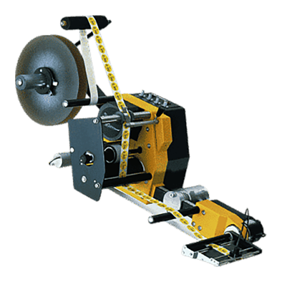
- Page 1 HM Collamat AG Bodenmattstrasse 34 CH-4153 Reinach Switzerland Phone +41 61 756 28 28 Fax +41 61 756 29 29 contact@collamat.ch www.collamat.ch Collamat 6600 Technical handbook...
-
Page 2: Table Of Contents
page Index 1 Safety advices .............. - Page 3 page Index 4.9 Motor and motorcable .............
- Page 4 18.1 Trouble shooting Collamat 6600 ........
-
Page 5: Safety Advices
Before installing and operating the Collamat 6600 read following safety instructions: The labeler C6600 is exclusively determinated for labelling goods. The installation of a Collamat 6600 has to be done by a trained specialist. For this you have to consider the national specific regulations of prevention of accidents... -
Page 6: Symbol Descriptions
Symbol descriptions ATTENTION Indicates danger of damaging the Collamat 6600 or other system compo- nents, with a potential consequential danger of injuries. DANGER Indicates an immediate hazard for persons. DANGER Shock hazard due to high voltage at component. DANGER Hazard due to high temperature component. -
Page 7: Introduction
The installation of the Collamat 6600 must be done by trained personnel. For this you have to con- sider the national specific regulations of:... -
Page 8: Prevention Of Accidents
These assemblies must be certificated by HM Collamat AG. 2.2.3 Mechanical stability If the Collamat 6600 is used on a movable stand, this stand must be capable to be tilt 10° in each direction. See also following figure 1: 10°... -
Page 9: Assembly Parts
2.3 Assembly parts The assembly parts are mounted and placed on a modular rail. Following figure 2 shows these as- sembly parts with their names on the modular rail: Figure 2: Assembly parts Legend Unwinder dancer Modular rail Unwinder Support Traction unit Adapter (optional with magnet) Paper brake... -
Page 10: Mechanical Adjustments
3 Mechanical adjustments 3.1 Traction unit 3.1.1 Threading the labelweb Figure 3 Thread the labelweb as shown in figure 3 up to the dispensing edge and draw it out by approx. 1m. Detach the labels from the paperweb at the drawn-out web. Then open the pinchroller by turning the knob 1, place the paperweb over the dispensing edge and finish threading the paperweb as shown in figure 3. -
Page 11: Readjustment Of Paper Brake
3.1.3 Readjustment of paper brake Figure 5 The braking force is factory-set to an optimum value. Should it, however, be unadjusted, readjust it with the M3-bolt 2 in the web-end controlbox of the traction unit, from the outside. higher braking force Screw in bolt = lower braking force Unscrew bolt =... -
Page 12: Flap Adapter
3.2 Flap adapter 3.2.1 Inclination adjustment of flap adapter Figure 7 The inclination of the flap adapter can be changed against the module rail: Unscrew nut 1 with two turns (refer to figure 7), with special hexagonal spanner (included as accessory). Push adapter in the direction indicated by the arrow 2, turn to desired setting at ring 3. -
Page 13: Adjustment Of The Optical Label Scanner
Proceeding of the adjustment of the optical label scanner: Switch on the Collamat 6600. Set the label scanner potentiometer to zero. Pull the labelweb so that the gap is located below the marking 1 of the scanner. Turn the potentiometer until the red LED on the scanner goes off. -
Page 14: Adjustment Of The Mechanical Label Scanner
3.4 Adjustment of the mechanical label scanner The mechanical label scanner (not used on magnetic flap adapter) is an alternative to the optical label scanner and is mainly used for transparent labels. 1. Scanner support 2. Scanning head 3. Nut 2 - 6 mm Figure 10 Adjustment:... -
Page 15: Technical Description
4 Technical description 4.1 Dispenser board All the electronic devices including power transformer, except of the main switch with indicator lamp, are located on a printed board. The dimensions of the board are approximately 215 x 234 mm. Figure 11 shows the board with all the connectors and terminals. The description is divided into power supply, motordriver, controller and firmware. -
Page 16: Signals And Connection Diagrams
The interference can lead to malfunction of the Collamat 6600. Anyway, installing the Collamat 6600 you have to consider the rules concerning RMI and ESD to prevent these interferences. See also chapter Cabling. -
Page 17: Inputs
The inputs are used to connect peripheral units and sensors. The inputs are activated while they are pulled to GND (0 Volt). The peripheral units from HM Collamat AG have NPN-outputs to 0 Volt. Figure 12 shows the schematic diagram of the inputs:... -
Page 18: Isolated Outputs
4.2.3 Isolated outputs These outputs are completely isolated to the electronic circuit of the labeler. Figure 13 shows the schematic diagram of the isolated outputs. The following outputs are available: ERROR Photocoupler, indicates an error condition (ERR) IFEED Photocoupler, isolated FEED-signal (IFD) Umax.: 24VDC Imax: 25 mA PC355T... -
Page 19: Currentsource-Output
4.2.5 Currentsource-output For the IR-transmitter of the label scanner TCY, a controlled currentsource is used. Figure 15 shows the schematic diagram of the currentsource: +12V OP-AMP 100k LM358 H8/532 BCP54-16 4 IR-LEDs 100n Figure 15: TCY-currentsource page 18 / 56 5999.525-01F 13.01. -
Page 20: Connection Diagrams Bus X101, X102
4.3 Connection diagrams BUS X101, X102 The buscable of the peripheral units is connected to the connectors X101 or X102. The cable must be placed inside of the module rail to prevent interferences. Figure 16 shows the position of the buscable connectors on the dispenser board: X102 X101... -
Page 21: Connection Of The Mains Input
The primary side of the transformer is connected to the terminals X46 and X48. Dependent to the mains voltage the transformer is connected as shown in figure 18: 110V 120V 220V 230V 240V 0 = black 2 = red 4 = yellow 5 = green 8 = grey 9 = white... -
Page 22: Connection Of The Mains Output
4.7 Connection of the mains output Peripheral units like the flatprinter or the adapter with magnet are connected to the mains output. To this terminal only units, certified by HM Collamat AG, may be connected. Figure 20 shows the mains output terminal:... -
Page 23: Motor And Motorcable
4.9 Motor and motorcable Attention: Never dismantle the motor ! Steppermotors heat up during operation ! When connecting or disconnecting the motor, the labeler has to be switched off ! While working on the motor, the labeler has to be disconnected from the mains ! The motor is connected inside of the labeler. -
Page 24: Firmware
5 Firmware 5.1 Normalmode After turning on the labeler, the DIL-switches are scanned to figure out the working mode. Then the DATA-HOLD-switch is scanned. Dependent to its position the data from the EEPROM are read out or the potentiometers are scanned. The dispensing of a label is triggered by the negative edge of GSC1 (Goods scanner input). -
Page 25: Dil-Switches
5.2 DIL-switches The dispenser board contains six DIL-switches. These switches are used to select different operat- ing modes. The following table and figure 24 show the functions and the positions of the DIL-switches: Switch Function TEST Labelingmode/ Testmode Labelingmode Testmode Slave Master Turning direction of the motor... -
Page 26: Dil-Switch Del
5.2.4 DIL-switch NS This DIL-switch selects the Nonstopmode. In the Nonstopmode two Collamat 6600 can be used to work in a zero downtimemode. For further information to the Nonstopmode, please read the chap- ter Nonstopmode. -
Page 27: Trouble Shooting
5*20mm 74031135 To exchange the fuses, the cover of the Collamat 6600 must be removed. If the fuse of the main voltage is blown, the indicator lamp of the power switch is not illuminated when the Collamat is switched on. -
Page 28: Peripheral Units And Sensors
7 Peripheral units and sensors 7.1 Optical label scanner +12V (LABEL SCANNER) G N D +12V TCY (TRANSPARENCY) Figure 25 7.2 Goods scanners 7.2.1 CS measuring IR-scanner LEDs Figure 26 7.2.2 NPN-Reflective scanner +12V GSC1 GOODS SCANNER G N D Figure 27 page 27 / 56 5999.525-01F 13.01. -
Page 29: Magnet Adapter
7.3 Magnet adapter GS070C TIME 14 Pol 3,15AT FLACHKABEL RECHTS LINKS +12 V M A G N E T +12V Ph N GS070D DELAY 14 Pol 3,15AT FLACHKABEL RECHTS LINKS +12 V M A G N E T +12V Ph N Figure 28 The mains voltage must be connected inside of the flap printer or inside of the dispenser. -
Page 30: Flatprinting Unit
Flatprinting unit 7.4.1 Flatprinter board rot / red rot, schwarz red, black schwarz / black braun / brown weiss / white Farbbandmotor Ribbonmotor Collamat Buskabel 14 polig Collamat Buscable 14 poles Figure 29 page 29 / 56 5999.525-01F 13.01. 2010 PS... -
Page 31: Control Signals For External Units
8.1 How to connect a goods scanner The goods scanners and incremental encoders are connected to the GSC1 and GSC2 connectors. Figure 30 shows the connection of the standard HM Collamat AG IR goods scanner: G N D +12V... -
Page 32: Electrical Installation
The transmitter (2 pole cable) and receiver (3 pole cable) of the optical label scanner can directly be connected to the dispenser C6600, to the flap adapter or to the flatprinter respectively. In this case, the connection to the Collamat 6600 is made by the 14 pole flatcable. page 31 / 56... - Page 33 P1/P2 +12V GSC1 +12V GSC1 GSC2 +12V +12V Figure 33: Connection diagram page 32 / 56 5999.525-01F 13.01. 2010 PS...
-
Page 34: Nonstop Labelling
10 Nonstop labelling When using two Collamat 6600, it is possible to label goods with no down time. For this purpose the two labelers must be connected together by an electrical link. The necessary links are shown in figure 34. The placement of the two Collamat to each other is shown in figure 35. -
Page 35: Setting Up Of The Nonstopmode
Service the erroneous condition on the stopped Collamat If an error occurs which stops both Collamat, first the error condition must be serviced. Then the Nonstopmode must be set up again, as described before. -
Page 36: Testmode
The DATA-HOLD switch is supervised. Dependent to its position, the potenti- ometer values are scanned or stored. In the testmode, the Collamat 6600 can be controlled by an ASCII-terminal or a PC with a terminal emulation software. The communication with the Collamat will be done through the connector X104 using the RS232 protocol. -
Page 37: Testprogram
11.1 Testprogram When the Collamat 6600 is connected to the terminal, it must be switched on. At this moment the DIL-switch TEST must be set to on. The traction unit begins to turn with the speed set on the SPEED potentiometer. The terminal shows the following message: COLLAMAT 6600 V1.011... -
Page 38: Motor Intervall Test
11.1.2 Motor intervall test The Motor intervall test tests the labelling functions of the Collamat 6600. If a label web is threaded through the dispenser, labels will be dispensed periodically with the speed set on the SPEED potentiometer. >n Motor intervall test. -
Page 39: Signal Display
Figure 38 shows the schematic diagram of the diagnostic connector: + 1 2 V + 1 2 V R E A D Y F E E D L S C G S C 1 T C Y G S C 2 R E S O U T C L K R E S I N... -
Page 40: Eeprom Data
Serial No.: 0007 11.2 Potentiometer parameters On the Collamat 6600 the potentiometers can be programmed. With this function the working range of the potentiometers can be matched to a special labelling condition. To enable the potenti- ometer programmability, the DIL-switch TEST must be set to ON. - Page 41 The function is called by pressing the O key. Then the Collamat 6600 gives the following message: >o Potentiometer parameters. Speed 30 m/min Predispensing 000 100 mm Position 100 mm Reset to factory settings SPACE : Exit Select function with the Keys S,P,O,R,SPACE The potentiometers can be selected with the S, P and O keys respectively.
-
Page 42: Incremental Encoder Programming
Now the entered values are displayed and a request to store it in the EEPROM is asked. SPEED limits Upper limit : 20 Lower limit : 10 Store data ? Y/N Pressing the Y key stores the data. This function will be skipped with the N key. If the datas are stored the following message will be displayed: Updating EEPROM..OK >... - Page 43 After pressing the ENTER key the following message will be displayed: New distance is : 157/100 mm : On : Off : Modify : Reset to factory settings ENTER : Keep SPACE : Exit Select function with the keys +,-,M,R,ENTER,SPACE Now the incremental encoder can be turned on by pressing the + key.
-
Page 44: Incremental Encoder
12 Incremental encoder The electrical connection of an incremental encoder is described in the chapter Connection of the goods scanners. The programming is described in the chapter Testmode. Now the mechanical attachment of the conveyor to the encoder will be described. If the speed measuring is done by an incremental encoder, the measured speed can be fine ad- justed by ±10 % with the SPEED potentiometer. -
Page 45: Control Of A Hotstamp With The Ifeed Signal
13 Control of a hotstamp with the IFEED signal Two different type of hotstamps (NPN or PNP) can be connected. Figure 39 shows how to connect different hotstamps. Figure 40 shows the timing diagram. C6600 HOTSTAMP C6600 HOTSTAMP NPN-Input PNP-Input +12V / +24V +12V / +24V CONTROL SIGNALS... -
Page 46: Cabling And Setting Up
14 Cabling and setting up For a trouble free operation of the Collamat 6600 following items must be observed: Trained personnel Ambient temperature Absence of dirt and dust Absence of splashing water Installation and setting up of the installation Installation and setting up of the Collamat 6600... -
Page 47: Version Numbers
GrouND Infra Red Light Emitting Diode not connected RS232 Standard serial data exchange protocol 16.2 Signals ERROR Errorsignal caused by any error of the Collamat FEED Signal indicating the labelling process GrouND Goods SCanner IFEED Isolated FEED signal Label SCanner... -
Page 48: Terms
Rewinder: Device that takes the empty paperweb from the traction unit and rewinds it CE-Mark: Certification for the European market, means: Conformité Européenne Collamat: Brand name for a labeler built by HM Collamat AG GSC: Goods SCanner Flap adapter with magnet: Adapter which moves down to the product during the labelling... -
Page 49: Technical Data
17 Technical data Dispenser general data (standard values) System Units C6610 C6620 Version right/left Dispensing speed m/min 3.0-30 Min. label width Max. width of the paperweb Min. label length Min. label length at max. dispensing speed Stop accuracy ± 1 mm at 30 m/min Minimal gap for optical scanner Minimal gap for mechanical scanner Max. - Page 50 Midi-unwinder Diameter of the roll core 42 mm Max. outside diameter of roll 350 mm Max. weight of roll 10 kg Spring dancer with automatic brake Flap adapter System C6610 C6620 Max. width of paperweb 95 mm 160 mm Weight 1.9 kg 2.2 kg Version...
-
Page 51: Dimensions - Systemdesign
17.1 Dimensions - systemdesign min. 225 max. 375 Ø 40 A) Abwickler A) Unwinder B) Vorzugwerk B) Traction unit C) Klappenadapter C) Flap adapter D) Für Deckelmontage D) For lid dismantling page 50 / 56 5999.525-01F 13.01. 2010 PS... -
Page 52: Troubleshooting
18 Troubleshooting 18.1 Troubleshooting Collamat 6600 The troubleshooting will proceed along the paperpath. See following figure: SPEED P O S T C Y X 4 8 X 1 0 3 X 1 0 6 X 4 6 RESET F A U L T... - Page 53 1. Unwinder troubleshooting SYMPTOM DIAGNOSIS ACTION Paperweb falls off in side label- Missing side labeling kit Mount the side labeling kit to ing applications the Collamat 2. Adapter troubleshooting SYMPTOM DIAGNOSIS ACTION Labels run through Roll-up cable is broken Replace roll-up cable...
- Page 54 2. Adapter troubleshooting SYMPTOM DIAGNOSIS ACTION Paperweb breaks behind the Lateral paperguides hurt the Enlarge the space between peeling bar paperweb the paperguides Paperbrake set too hard Reduce the braking force Peeling bar is too sharp Use peeling bar with a bigger radius Add Teflon tape around the peeling bar...
- Page 55 Motor turning direction is wrong Wrong DIL-switch DIR setting Change DIL-switch DIR Wrong Motor wiring Reconnect motor wires ac- cording to the Technical Handbook Collamat labels only at 3m/min Labeler is set to incremental Change DIL-switch R2 to encoder Motor makes noise and shakes. Faulty motor driver chip...
- Page 56 4. Control print troubleshooting SYMPTOM DIAGNOSIS ACTION The RESET LED periodically Microprocessor error Replace the board flashes EPROM faulty Replace the EPROM page 55 / 56 5999.525-01F 13.01. 2010 PS...
-
Page 57: Trouble Shooting Checklist
18.2 Trouble shooting checklist Ser. No. Dispenser board: Ser. No. Labeler: Machine-Type: Mains voltage: Frequency Hz: Temperature °C: Environment Interference level (Burst): Interference level ESD Humidity % (Static): Width: Length: Gap: Labels Thickness: Transparency: Material: Width: Thickness: Transparency: Paperweb Kind: Material: Shape: Goods...
Need help?
Do you have a question about the 6600 and is the answer not in the manual?
Questions and answers