Table of Contents
Advertisement
Quick Links
Inhalt
Technical Handbook
Collamat S Series
Doc. ID: TH-CO-S-EN
Release: V1.15/11/2013
Read the Technical Handbook before performing any work on the machine!
The German-language version of this Technical Handbook is the only
official original version. Any Technical Handbook translated into other
languages (or excerpts of it) are only references to this original
version.
Advertisement
Table of Contents

Related Manuals for Collamat S Series


Summary of Contents for Collamat S Series
- Page 1 Inhalt Technical Handbook Collamat S Series The German-language version of this Technical Handbook is the only Doc. ID: TH-CO-S-EN official original version. Any Technical Handbook translated into other Release: V1.15/11/2013 languages (or excerpts of it) are only references to this original version.
- Page 2 22-12-2011 V1.13 Translations & corrections - ps Switzerland 23-12-2011 V1.14 Translations & corrections – ps 27-11-2013 V1.15 Translation of nonstop part – Collamat S - ps Tel.: +41 (0) 61 756 28 - 28 Fax: +41 (0) 61 756 29 - 29 E-Mail: info@collamat.ch...
-
Page 3: Table Of Contents
Collamat S Series General General ...............................6 Information about the Technical Handbook ..................6 Technology ..............................7 Software/Firmware ..........................7 The traction unit ...........................8 Components............................9 2.3.1 Front view .............................9 2.3.2 Rear view ............................10 2.3.3 Front view traction unit........................11 Assembly examples ...........................12 2.4.1 General information’s to IP54 version ..................14 Components ............................15... - Page 4 Collamat S Series General 3.1.3 Setup ............................50 3.1.4 Nonstop Control-Table ....................... 51 3.1.5 Nonstop cabeling ........................52 Inputs + Outputs ............................. 53 Inputs + Outputs (Electronic)......................53 4.1.1 Inputs ............................53 4.1.2 Label sensor – inputs ......................... 56 4.1.3 Outputs............................
- Page 5 Collamat S Series General 6.4.25 Details to Menu - Service - Set Outputs ...................101 6.4.26 Directions to naming of inputs/outputs ..................101 Index ...............................102 Index of documents in the Appendix ....................103 Release: V1.15/05/2013...
-
Page 6: General
The Collamat S Technical Handbook (abbreviated as TH in this document) is considered the technical element of the operating instructions. The TH should help you to use the Collamat S to its fullest. The description of the individual mechanical and electrical components also helps for rapid troubleshooting and problem solving in case of faults. -
Page 7: Technology
Collamat S Series Technology 2 Technology 2.1 Software/Firmware The control program for the Collamat S has the following features: dual processor hardware allows for rapid parallel processing for communication and drive control modern user interface preset and print run counter ... -
Page 8: The Traction Unit
Nonstop-Cabling-Set (two Collamat S are used – only one incremental encoder will be used in speed mode: TACHO). Several helpful options are available to increase the performance and comfort of a Collamat S. These are the most important options: Electrical rewinder unit (ERW) -
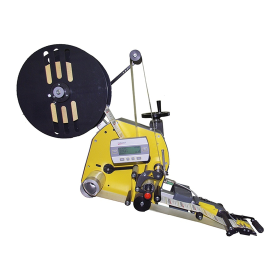
Page 9: Components
Collamat S Series Technology 2.3 Components Description The individual components with their setup options and maintenance are described here. This section begins with a general overview of the dispenser. The components are mounted on a module rail. Figure x shows these components and their names mounted on the module rail: 2.3.1 Front view... -
Page 10: Rear View
Collamat S Series Technology 2.3.2 Rear view Fig. 2-2 Pressure roller adapter 11 Unwinder front plate Dispensing edge adapter 16 Side connection plate, "power" Clamping piece module rail 40/40 x 50 17 Adjustment wheel, dispenser applicator Side connection plate, "SIGNALS"... -
Page 11: Front View Traction Unit
Collamat S Series Technology 2.3.3 Front view traction unit Traction unit in detail Drive Operator panel (keypad + LCD) Module rail flange Paper brake opener Module rail Paper brake Traction cylinder Side connection plate, "SIGNALS" Rewinder pendulum Pressure roller for traction cylinder... -
Page 12: Assembly Examples
The following assembly examples have produced good labeling results. Example 1 - Clamping piece on module rail Example 2 - Clamping piece on housing floor Example 3 Horizontal position of Collamat S - Clamping piece on housing floor Release: V1.15/05/2013... - Page 13 Example 4 Horizontal position of Collamat S - Clamping piece on module rail Example 5 Horizontal position of Collamat S - 2 clamping pieces on module rail Example 6 – Collamat S "overhead" - clamping piece on housing floor or module rail Release: V1.15/05/2013...
-
Page 14: General Information's To Ip54 Version
The side connection plate “SIGNALS” is available with or without D-SUB connectors/plugs. INFORMATION! Pay attention to the different IP54 directions in the Collamat S Series Operator Manual. IP54 units have to be intensely maintained every 12 month (see also chapter Maintenance in the Collamat S Series operator manual). -
Page 15: Components
Setup of software parameters and monitoring of the spender are performed at the operator panel. The Collamat S housing may only be opened for a "one-time" setup and for service work. Unscrew the four screws on the rear wall to open the housing from the rear. - Page 16 This ensures that the rewinder coil is held at a perfect position despite reverse slippage. Order text: Collamat S xx - WW D (xx=max speed, WW=Width, D=Direction). The pendulum of the rewinder damps the carrier paper movement.
-
Page 17: Electronics - Control Unit
Collamat S Series Components 3.2 Electronics - Control unit DANGER! The electronics of the control unit may not be touched without taking precautions against ESD. The electronics are sensitive to direct electrostatic discharge. Master controller The heart of the main control unit is a dual-processor system consisting of a master controller and a slave controller. - Page 18 Motor controller motor controller is a component developed and built by a renowned step motor controller producer. Standard parameters for using the Collamat S are 80V DC / 5.1/6A – 2000 steps / revolution – automatic current reduction. Power power for the electronics is delivered by a high-powered toroidal transformer.
- Page 19 Collamat S Series Components Measurements of the master controller and piggyback board HMC0601V3-5 – 17.11.2011: Print Modifications R63, R64 = 560E C29 = 22uF/35V R14-19, R23-25, R29 = 560E J9, J10 = MSTBVA 2,5/ 2-G-5,08 (1755736) Heathsink – new drillings:...
-
Page 20: Details For The Main Control Unit
Collamat S Series Components 3.2.1 Details for the main control unit Connection terminals and plugs Description Cable 58V toroidal transformer, motor voltage, screw terminals 2 red wires 27V toroidal transformer, logic voltage, screw terminals 2 blue wires Step motor, motor controller, power plug... - Page 21 Collamat S Series Components Fuses If the electronic fuses F1 or F2 have triggered, this indicates that an overload or short-circuit is present on one of the loads connected to plugs J6, J7, J8 and ..After the short-circuit or overload has been corrected, the corresponding fuse is reactivated after briefly turning it on and off.
- Page 22 Collamat S Series Components PE - connections (blade terminals) The PE – connections (earthing terminals) are located at the bottom right and left of the main control unit are labeled X3 and PE (left): PE (right): Earthing terminals (PE terminals) create a connection to the housing frame, the "Power"...
-
Page 23: Changing The Main Control Unit
Collamat S Series Components PE cable Description Cable HMC06CA14 PE power cable Connections 1, 2 + 3 HMC06CA15 PE cable, adapter housing to traction unit Connection 4 HMC06CA28 PE connector board cable Connection 5 HMC06CA27 PE cable, adapter housing to board... -
Page 24: Firmware Versions
The manufacturer of the Collamat S or its local representatives have special programming devices for this purpose. Normally, the end user does not have these programming devices available, so Collamat AG offers a special update service by chip or board. The following firmware update services are available: ... -
Page 25: The Side Connection Plate "Signals
Collamat S Series Components 3.4 The side connection plate “SIGNALS” view from the outside from version Y to … up to version V … Connections Function Plug - Connector Nonstop Nonstop labeling with two labelers 15-pin D-Sub plug Opt. RS232... - Page 26 Collamat S Series Components Jumper-Control-input [JP2] e.g. bright- / dark-switching (JP3-CNTR.): The control line has to be connected to GND, to +24V or left open - depending on the brand of the good scanner. The most common function for the control line is:...
-
Page 27: The „Gsc" M8-Plug
Connect white molex plug to M8-PLC connector. 3.4.3 The „TACHO“ M12-plug Pin assignmen The plug type for the incremental encoder cable is a 4-pin M12 plug. The pin assignment of this plug is according to the Collamat S standard: Pin 1: +24V ... -
Page 28: Operator Panel
Collamat S Series Components 3.5 Operator panel Operator Panel The operator panel is mounted at the upper guide roller of the unwinder. The position of the operator panel can be turned to the optimum operator position, depending on the position of the dispenser. The operator panel electronics can be removed from the housing by unscrewing the mounting screws at the rear. - Page 29 Collamat S Series Components Replacing the LCD DANGER! When replacing the LCD module, note the warranty limitations. There is no warranty for broken LCDs. Unauthorized manipulation of the components will annul the warranty. LCD display - rear and front LCD terminal interface board HMC0609-x - Contrast settings with R1...
-
Page 30: The Ndc06 Motor Controller (Mc)
Collamat S Series Components 3.6 The NDC06 motor controller (MC) Note The motor end stage is a component developed and built by a renowned step motor controller producer. The end stage is also known as the motor controller (MC). MC NDC06... -
Page 31: Settings For The Mc
Collamat S Series Components 3.6.2 Settings for the MC DIP - switches and jumpers Dip switch DP1; 3, 6 and 7 – ON 1, 2, 4, 5 and 8 - OFF (Standard Motor: SM2862-5155) Rated current: 5.1 A: Dip switch DP1; 6 and 7 – ON... -
Page 32: Status Led For The Mc
Collamat S Series Components 3.6.3 Status LED for the MC MC status LED Status Explanation Operating voltage in acceptable range Green HV a – over temperature, if TER LED is <on> b – overvoltage or under voltage, if HV LED is <off>... -
Page 33: Feed
Collamat S Series Components 3.7 FEED Signal status The IFEED signal is always active while the step motor is turning. This signal can communicate to an external printer unit that paper is moving or not. The printer system analyzes the curves of this signal for printing to determine that the paper is not moving. -
Page 34: Controlling External Devices
Collamat S Series Components 3.8 Controlling external devices Controlling a hot stamp with IFEED Hot stamps are connected to the IFEED signal as follows: The IFEED signal is available at the "SIGNALS" connection plate at plug X4 of the connection box - or, optionally, at the connection box / on the connection module. - Page 35 NPN / PNP inputs Optical coupler inputs with included anode and cathode connections can be connected individually. Pre-resistance in the anode cable is already installed. The following inputs of the Collamat S follow this input principle: GSC_P GSC_N ...
- Page 36 24V at the anode side. A 2K2 resistor in the cathode cable ensures proper current limiting. These inputs can be switched very easily by establish a short- circuit against GND. The following inputs of the Collamat S follow this input principle: ...
-
Page 37: Incremental Encoder (Optional)
4 * 2000 pulses Example 2: The Collamat S (blue wheel) incremental encoder 1 sends one pulse per 0.1 mm. The incremental encoder wheel is driven by conveyor belt 2. Both rising and falling waves at outputs A and B are counted. -
Page 38: Hardware Data For The Incremental Encoder
M12 plug: MURR Elektronik – Part.Nbr. 7000-12491-0000000 The turning direction of the incremental encoder will be automatically detected by the Collamat S. See mounting Caution: direction (arrow) of the encoder on the picture below. The encoder should be pulled (and not pushed) by the conveyor belt. - Page 39 M12 plug: MURR Elektronik – Part.Nbr. 7000-12491-0000000 The turning direction of the incremental encoder will be automatically detected by the Collamat S. See mounting Caution: direction (arrow) of the encoder on the picture below. The encoder should be pulled (and not pushed) by the conveyor belt.
-
Page 40: Etikettierung - Theorie
First check before starting: Standard Mode Before starting a dispensing sequence (dispensing a label), a few important parameters have to be checked first by the Collamat S firmware: Position: Check of the Position value / Position delay (see drawing). ). A too short... - Page 41 Collamat S Series Components Speed - Compensation (SPEED COMP): Compensation value = distance resulting from the …continue with speed difference between product speed and ramping up motor speed – while in the RAMP Standard Mode UP section of the label movement. Remember: the higher the product speed the higher the compensation value! This explains the pre starting of a labeling sequence : Position delay = POSITION value minus SPEED COMP.
- Page 42 Collamat S Series Components „Fast Speed Mode” = fast labeling with short labels! „Fast Speed“ The course of action in the „Fast Speed Mode” is similar to the above described “Standard Mode Mode”. However – a few parameters are treated different, to make the unit running faster (especially for short labels).
- Page 43 „Fast Speed Mode” Observation / Adjustment: Before starting and/or while running a label dispensing sequence, a few important parameters have to be checked by the Collamat S firmware / by the operator: Position: Check of the Position value / Position delay (see above). A too short value connotes: the motor is not able to speed up and reach the calculated “point...
-
Page 44: Electrical Rewinder
For a dispenser that runs from "left to right" (called a "right-sided dispenser" by Collamat AG), the internal assembly screw in the sensor board is coded to "right". The monitoring cable transmits the following parameters (main computer to/from 4Q-MC) via J3 control inputs/outputs: ... -
Page 45: Status Leds On The Mc
Collamat S Series Components 3.11.2 Status LEDs on the MC Status LED Status of the 4Q rewinder motor controller Description GREEN Operating voltage active The motor controller is in error mode or disabled. 3.11.3 Electrical connections Socket J3 - CONTROL... - Page 46 Collamat S Series Components Socket J1 – CONTROL (Version A) Signal Description Ground not used U4(S1) Sensor position 1 - pendulum position U3(S2) Sensor position 2 - pendulum position U2(S3) Sensor position 3 - pendulum position U1(S4) Sensor position 4 - pendulum position...
-
Page 47: Voltage Supply
Collamat S Series Components 3.11.4 Voltage supply Transformer To operate the electrical rewinder unit, a special transformer (460VA) is needed that supplies the necessary energy to the 4Q- MC (24V AC). 3.11.5 Mechanics Drive / Control The following points must be checked before first using the electrical rewinder: ... -
Page 48: Non-Stop Labeling
3.1 Non-stop labeling 3.1.1 Short description It is possible to label goods without interruptions – by using two Collamat S.. For this purpose, both Collamat S units must be connected to one another electrically. The necessary connections are shown in Fig.3.9.5. -
Page 49: Assembly
Collamat S Series Components 3.1.2 Assembly Setup for two Collamat S units in non-stop operation Machine type: right-sided Dispenser left: Master Dispenser right: Slave 1 = goods sensor (Master GSC) 2 = goods sensor (Slave GSC) 3 = incremental encoder (Master + Slave TACHO) -
Page 50: Setup
(<enter>-key. Then, remove all goods between the GSC units before clearing the non-stop counter on the Collamat S Master. An erroneous slave demanding an immediate stop will inform the master by sending a short puls on the NSTP-OUT line (= NSTP-IN on the master nonstop connector) –only in the situation for nonstop... -
Page 51: Nonstop Control-Table
Collamat S Series Components 3.1.4 Nonstop Control-Table Voltage* Voltage* Products Products Pin 13 to GND Pin 11 to GND btw. MS-SL btw. MS-SL Master (MS) Slave (SL) MS: NSTP-OUT MS: NSTP-IN With label Comment Counter MA-SL stopped** stopped** stopped** ready... -
Page 52: Nonstop Cabeling
Collamat S Series Components 3.1.5 Nonstop cabeling Release: V1.15/05/2013... -
Page 53: Inputs + Outputs
4 Inputs + Outputs 4.1 Inputs + Outputs (Electronic) Explanation This chapter describes the signals of the Collamat S in detail. All input and output signals are described electrically and functionally. The plug positions on the "SIGNALS" connection plate and the pin positions of the input/output plug adapter have already been described in the chapter "SIGNALS"... - Page 54 Collamat S Series Inputs + Outputs NPN inputs with common GND Input Description Pushbutton on adapter – dispense one label DISP Change operating mode – from STOP to RUN START Change operating mode – from RUN to STOP STOP Ready input...
- Page 55 Collamat S Series Inputs + Outputs Optical coupler input with separate cables On: 7.5 mA @ 24V DC Off: 0 mA: Vmax: 28V DC Explanation The figure above shows a diagram of optical coupler inputs with separate anode and cathode cables.
-
Page 56: Label Sensor - Inputs
4.1.2 Label sensor – inputs Explanation The only analog inputs in the Collamat S are the two inputs of the label sensor. The standard label sensor consists of an OP550A phototransistor receiver that is built into the housing of the sliding label sensor head. - Page 57 Collamat S Series Inputs + Outputs Explanation Analog label sensor input - shown here is the example of a "transmissive sensor" - "Sensor 1" on the adapter board HMC0605 and on the main control board HMC0601. The following input signals fall under this category of analog...
-
Page 58: Outputs
Collamat S Series Inputs + Outputs 4.1.3 Outputs For the outputs, there are different types of switching mechanisms: PNP – outputs The following figure shows a basic diagram for a PNP output: 24V DC Umax: 28V DC The following output signals fall under this category:... - Page 59 Collamat S Series Inputs + Outputs The following output signals fall under this category: Description RW_ENABLE_C RW_ENABLE_E Rewinder enable input RW_WIDTH_C RW_WIDTH_E Rewinder width input ERR_OPT_C ERR_OPT_E Error Output WAR_OPT_C WAR_OPT_E Warning Output RUN_OPT_C RUN_OPT_E Run Output PROD_OUT_C PROD_OUT_E Product-Counter Output...
- Page 60 Collamat S Series Inputs + Outputs Open collector output This is an internal output signal on the Collamat S and may only be used for controlling the label sensor transmitter stage. not galvanically separated! The following figure shows a basic diagram for this output:...
-
Page 61: Inputs + Outputs (Description)
The signal LLO (Label LOw) serves to monitor the roll diameter at the unwinder. The standard monitoring sensors from Collamat AG are fitted with NPN outputs (active L). (optical coupler input – 10K series resistor) The RWF signal (ReWinder Full) serves to monitor the roll diameter of the rewinder. - Page 62 (optical coupler input - 3K3 series resistor) The START input can be used to start the Collamat S. This function corresponds to the RUN/STOP button on the operator panel. If the signal is activated when the system is stopped, the Collamat will be START started (RUN).
- Page 63 Collamat S Series Inputs + Outputs Inputs (continued) Input Description Sensor 1: (fiber optic type) The LSC_T input is connected with the transmissive label sensor receiver. To allow for highly precise sensor function, LSC_T this input is given a very small damping time. With this input, only the CAG fiber optic receiver can be used as a label sensor receiver.
-
Page 64: Output Details
Output Description This signal transmission controls the step motor end stage (speed control). RTA_STEP This is an "internal" signal transmission for the Collamat S. (PNP, 2K2 Shunt) This signal transmission controls the step motor end stage (rotational direction). RTA_DIR This is an "internal" signal transmission for the Collamat S. (PNP, 2K2 Shunt) The FLAP signal controls the electromagnet flap adapter. - Page 65 (GSC input = GSC output). GSC_OUT (Open collector output – no shunt – emitter at GND) This is an "internal" output signal on the Collamat S and may only LSC_PWM be used for controlling the Collamat S label sensor transmitter stage.
-
Page 66: Maintenance
Collamat S Series Maintenance 5 Maintenance 5.1 Safety Basics WARNING! Danger of injury due to improper maintenance work! Incorrect maintenance can cause serious injury or damage. Therefore: Maintenance work may only be performed by qualified and owner-authorized and trained personnel. - Page 67 Collamat S Series Maintenance Electrical equipment DANGER! Danger of death due to electrical current! Contact with live components can cause danger of death. Electrically driven components can start to move without warning and cause extremely serious injuries. Therefore: Before beginning work, turn off electricity supply and ensure that it cannot be turned- back on.
-
Page 68: Maintenance Schedule
Collamat S Series Maintenance 5.2 Maintenance schedule The following sections describe the maintenance work necessary for optimum and fault-free operation. The maintenance intervals are to be observed. If the regular checks show increased wear of individual components or functional assemblies, the operator must shorten the maintenance intervals according to the actual wear. -
Page 69: Cleaning
Collamat S Series Maintenance 5.3 Cleaning If superficial dirt is noted, proceed as follows: 1. Switch off the machine and secure against switching on again. 2. Remove dirt correctly. Note: Do not use aggressive cleaning agents. Absorb oil deposits with oil-absorbing materials (e.g. -
Page 70: Faults, Repair And Maintenance Work
Collamat S Series Faults, repair and maintenance work 6 Faults, repair and maintenance work This chapter describes the possible causes of faults, and the work needed to remedy these. If there is an increase of similar faults due to greater than average use, the maintenance intervals must be shortened according to the actual use. - Page 71 Collamat S Series Faults, repair and maintenance work Electrical equipment DANGER! Danger of death due to electrical current! Contact with live components can cause danger of death. Electrically driven components can start to move without warning and cause extremely serious injuries.
-
Page 72: Restarting After Remediation Of Faults
Collamat S Series Faults, repair and maintenance work Environmental protection Observe the following environmental protection instructions when remedying faults: At all lubrication points which are provided with lubricant manually, remove escaping, used, or surplus grease and dispose of according to the local regulations. -
Page 73: Table Of Faults
Collamat S Series Faults, repair and maintenance work 6.3 Table of faults Fault To be Possible cause Remedy performed by Machine cannot be No mains power Check power supply Operator switched on Defective device fuse Replace fuse Electrician or manufacturer... -
Page 74: Performing Maintenance And Repair Work
Collamat S Series Faults, repair and maintenance work Fault To be Possible cause Remedy performed by Drive motor turns Motor overloaded Determine the cause of the Specialist off (display on overloading and remedy it, e.g. operator panel) high friction of the label strip. -
Page 75: Replacing The Pressure Roller
Collamat S Series Faults, repair and maintenance work 6.4.1 Replacing the pressure roller The pressure roller is a wear part that can suffer wear and damage more Traction drive or less quickly depending on usage and handling. When labeling, ensure... -
Page 76: Changing The Traction Cylinder
Collamat S Series Faults, repair and maintenance work 6.4.2 Changing the traction cylinder If the traction cylinder is damaged or worn, it must be replaced. Traction drive Procedure: Unscrew and remove the support screw (1). Replacing the traction cylinder ... -
Page 77: Setting The Belt Tension (Traction)
Collamat S Series Faults, repair and maintenance work 6.4.3 Setting the belt tension (traction) If the label strip is not being transported correctly, the timing belt may Traction drive need to be adjusted. Procedure: Setting the belt tension Remove the housing cover on the back. For this, remove the six screws. -
Page 78: Changing The Timing Belt (Traction)
Collamat S Series Faults, repair and maintenance work 6.4.4 Changing the timing belt (traction) Feed drive Procedure: Remove the housing cover on the back. Loosen the belt tensioner (1) Replacing the timing belt Unplug the cable (2) from the stepper motor (3) at the motor controller (4) ... -
Page 79: Changing The Drive Motor (Traction)
Collamat S Series Faults, repair and maintenance work 6.4.6 Changing the drive motor (traction) Traction drive If the drive motor is damaged, it must be replaced. Replacing the step motor Procedure: Remove the housing cover on the back. For this, remove the six screws. -
Page 80: Ligth Tube / Sender Board Replacement
Collamat S Series Faults, repair and maintenance work 6.4.7 Ligth tube / Sender board replacement Adapter / applicator If the fiber optic cable of the label sensor can no longer be cleaned or is damaged or dull, it must be replaced... -
Page 81: Adjusting The Rewinder Pendulum (Rw Active + Passive)
Collamat S Series Faults, repair and maintenance work 6.4.8 Adjusting the rewinder pendulum (RW active + passive) Rewinder unit Set the spring tension so that the retraction force is no stronger than needed for the pendulum to return to its zero position (to the upper stop = (active and passive) paper tear position). -
Page 82: Setting The Belt Tension (Rw Passive)
Collamat S Series Faults, repair and maintenance work 6.4.9 Setting the belt tension (RW passive) Passive rewinder If the carrier paper is not rolled up cleanly by the rewinder, the timing belt may need to be adjusted. Procedure: Adjusting the belt tension ... -
Page 83: Changing The Timing Belt (Rw Passive)
Collamat S Series Faults, repair and maintenance work 6.4.10 Changing the timing belt (RW passive) Passive rewinder If the timing belt is damaged, it must be replaced. Procedure: Replacing the timing belt Remove the housing cover on the back. For this, remove the six screws. -
Page 84: Adjusting The Friction Clutch (Rw Passive)
Collamat S Series Faults, repair and maintenance work 6.4.11 Adjusting the friction clutch (RW passive) Passive rewinder If the drive for the passive rewinder is not functioning properly, the friction clutch settings must be checked first (see corresponding chapter later in the manual). If the friction clutch can no longer be Adjusting the friction clutch adjusted, the clutch pads must be changed. -
Page 85: Reconditioning The Clutch Disks (Rw Passive)
Collamat S Series Faults, repair and maintenance work 6.4.12 Reconditioning the clutch disks (RW passive) Passive rewinder If the drive for the passive rewinder is not functioning properly, the friction clutch settings must be checked first (see corresponding chapter later in the manual). If the friction clutch can no longer be Replacing the clutch disks adjusted, the clutch pads must be changed. -
Page 86: Setting The Belt Tension (Rw Active)
Collamat S Series Faults, repair and maintenance work 6.4.13 Setting the belt tension (RW active) Optional Electric rewinder If the carrier paper is not cleanly rolled up by the optional electrical rewinder, the belt tension must be checked and adjusted if necessary. -
Page 87: Changing The Rewinder Board (Rw Active)
Collamat S Series Faults, repair and maintenance work 6.4.15 Changing the rewinder board (RW active) Optional electric rewinder Replace the defective rewinder board HMC0607-x: Remove all plugs from the board Replacing the rewinder board Remove the 2 fixing screws (front plate) ... -
Page 88: Replacing Rewinder-Sensor-Board Ersetzen (Rw Activ)
Collamat S Series Faults, repair and maintenance work 6.4.16 Replacing Rewinder-Sensor-Board ersetzen (RW activ) Optional electrical rewinder Replacing defective Rewinder-Sensor-Board HMC0608-x: Replace Rewinder-Sensor-Board remove rewinder dancer flag remove the two fixing screws (board to front plate) remove the sensor cable (from the board) Replacement board: ... -
Page 89: Changing The Rewinder Motor (Rw Active)
Collamat S Series Faults, repair and maintenance work 6.4.17 Changing the rewinder motor (RW active) Optional electric rewinder If the drive motor of the optional electric rewinder is damaged, it must be replaced. Procedure: Replacing the DC motor Remove the housing cover on the back. For this, remove the six screws. -
Page 90: Replacing The Mainboard (Hmc0601)
Collamat S Series Faults, repair and maintenance work 6.4.18 Replacing the mainboard (HMC0601) Replacing the control unit Replace the defective control unit (slave controller): (mainboard) Disconnect all plug connections Unscrew the transformer cable (2 red cables / 2 blue cables) ... -
Page 91: Firmware Update - Master-Controller (Rcm4010)
Install the programming firmware Dynamic C (V 10.66) to your unit (Mainboard) PC/Laptop. Default directory: C:\Programme\DCRABBIT_10.66\ The „Flash Image“ file will be generated by Collamat AG (with the Dynamic C Software: Compile Project to .bin File = MAIN-V1-02.BIN = Version: V 1.02 (FDT3 Data File) -
Page 92: Firmware Update - Slave-Controller (Dspic)
Project – Build All: …. wait for message: BUILD SUCCEEDED HEX-file has been stored as: NG PIC.HEX Collamat AG will provide this HEX-file for downloading. Name: NG PIC V-VV-BL.HEX – whereas V-VV indicates the corresponding version number and BL the boot loader version e.g. - Page 93 Collamat S Series Faults, repair and maintenance work Prepare programming: Switch OFF Collamat S unit. Connect MPLAB ICD2 (ICD3) to Computer (USB/COM) Start MPLAB IDE File – Import: path – open NG PIC V-VV-BL.HEX Connect MPLAB ICD2 (ICD3) cable to main board...
- Page 94 Boot loader (ds30loader.s) Project – Build All: …. wait for message: BUILD SUCCEEDED HEX-file has been stored as: NG PIC.HEX Collamat AG will provide this HEX-file for downloading. Name: NG PIC V-VV.HEX – whereas V-VV indicates the corresponding version number e.g. .”...
- Page 95 HEX-file: NG PIC V-VV.HEX, device: dsPIC33FJ – 12MC202, baud rate: 9600, enable write program, Port: serial port (for example COM1) or USB-port (COM4(USB)). Power ON Collamat unit and – press the Download button within the next 5 second. Wait for the message „Download finished“...
-
Page 96: Details To Menu - Service - Read Pic Reg 0-63
Collamat S Series Faults, repair and maintenance work 6.4.22 Details to Menu - Service - Read PIC reg 0-63 Read PIC reg 0-63 You will find the complete menu structure in the corresponding Operator Manual of Collamat S Series – from chapter 7.8. ….. - Page 97 Collamat S Series Faults, repair and maintenance work Register 20: REG_StartDelay Registers[20] // 1/16mm Read PIC reg 0-63 Start (position) delay [1/16mm] continuation Register 21: REG_Predispense Registers[21] // steps (label stop) position after LSC edge detect Register 22: REG_Predispense2 Registers[22]...
- Page 98 Collamat S Series Faults, repair and maintenance work Register 51: REG_MultiReserved Registers[51] Read PIC reg 0-63 // Multiple Mode: reserved continuation Register 52: REG_MultDist0 Registers[52] // 1/16mm // Multiple Mode: distance between label edges Register 53: REG_MultDist1 Registers[53] // Multiple Mode:...
-
Page 99: Details To Menu - Service - Inputs
Collamat S Series Faults, repair and maintenance work 6.4.23 Details to Menu - Service - Inputs Inputs Use this function for technical inspections or for maintenance works to check/read the inputs of the dsPIC – register wise: (ext.) Register CS0: Piggy-Board [AVA / X-WEB]... -
Page 100: Details To Menu - Service - Read Outputs
Collamat S Series Faults, repair and maintenance work Inputs (…) (int.) Register PE: internal Register continuation PE0: GSC - Goodscanner input PE1: RUN - from dsPIC (RB3) PE2: TXF - to RS232 PE3: RXF - from RS232 PE4: open - N.U. -
Page 101: Details To Menu - Service - Set Outputs
(int.) Register PB - B0: START2 to dsPIC - for internal use only! 6.4.26 Directions to naming of inputs/outputs Naming Schematic version 3.4: The schematic of the Collamat S unit has been updated. Actual version: 3.4 The following inputs/outputs have been renamed: Name inconsistencies: Old: AUX_INX... -
Page 102: Index
Collamat S Series Index 7 Index Maintenance and repair work......68 Maintenance schedule ........62 Appendix ............93 MC NDC06............27 Assembly examples ........... 12 Motor controller ..........27 Cleaning............. 63 Non-stop labeling ..........42 Components........... 9, 15 Controlling external devices....... 31 Operating Instructions .......... -
Page 103: Index Of Documents In The Appendix
Collamat S Series Index of documents in the Appendix 8 Index of documents in the Appendix Index Description Art. No. CE - Conformity Declaration CE - Declaration of Incorporation RoHS - Conformity Declaration UL- / CSA - Conformity Lifting of loads... - Page 104 - EN ISO 141121-1 Safety of machinery, Risk assessment. Principles. Remark: The CE-Declaration of Conformity is valid only – if the Collamat S is safely mounted on a (Collamat AG) approved rack/stand. Issued in Reinach: 25. Novembre 2013 Collamat AG – Bodenmattstrasse 34, CH-4153 Reinach, Switzerland Authorized person: CEO - Frank Ankersen Release: V1.15/05/2013...
- Page 105 Responsible person for the composition of all technical documents according to Appendix VII – chapter B of the Directive on Machinery 2006/42/EG is: Collamat AG, Paul Schneider, Bodenmattstrasse 34, CH-4153 Reinach, Switzerland Issued in Reinach: 25. Novembre 2013 Collamat AG – Bodenmattstrasse 34, CH-4153 Reinach, Switzerland Authorized person: CEO - Frank Ankersen Release: V1.15/05/2013...
- Page 106 2003), if a „local“ professional waste management by the abroad reseller - according to WEEE2 – is not available. Collamat AG has taken all necessary steps to ensure the accuracy of this statement. The declaration is only binding for Collamat products that are purchased after the production date 13.02.2003.
- Page 107 PCBs: The board material for all Collamat S printed circuit boards (PCBs) conform with fire protection category UL 94 / V0 (category QMZS2) The production and mounting process of the PCBs is performed in a UL accredited production process (ZPMV2) UL94 = „Tests for Flammability of Plastic Materials for Parts in Devices and Applications“...
- Page 108 (near the ground) to the label dispenser Collamat S (generally at working height / conveyor belt height). If label rolls of more than 15 kg are loaded onto a standard Collamat S, the unwinder unit must be supported with a stabilization set.
- Page 109 Collamat S Series Register F Error checklist Device type: Ser.No. Dispenser: Collamat S xx-WW D xx = max.speed: 50, 100, 300 = ……… No. …………………… WW = width: 10,20,30 WW = ……… (100/180/250mm) = ……… D = direction (L/R) Environment:...
- Page 110 Collamat S Series Register G Wiring block diagram Release: V1.15/05/2013...
- Page 111 Collamat S Series Register H Boards (PCB) and cables ___________________________________________________________________________________________________________ Board numbers, Collamat S (HMC06) ___________________________________________________________________________________________________________ Name Description Version Measures Part- Drawing- [mm] number number ___________________________________________________________________________________________________________ HMC0601 Main-Board 306 x 106 52180266 152188007 HMC0602 Connector-Board 96 x 55 52180401 152180401...
- Page 112 Collamat S Series ___________________________________________________________________________________________________________ Cablenumbers Collamat S (HMC06) ___________________________________________________________________________________________________________ Name Description Pins Length Part- Stand. Drawing- [mm] number number _________________________________________________________________________________________________________ HMC06CA01D TUNIT sensorcable 52180271 152188558 HMC06CA02F LLO sensorcable 52180421 152180421 HMC06CA03A RWF sensorcable 52180422 152180422 HMC06CA04C OOL sensorcable 52180423 152180423...
- Page 113 Collamat S Series ___________________________________________________________________________________________________________ Name Description Pins Length Part- Stand. Drawing- [mm] number number _________________________________________________________________________________________________________ HMC06CA31A Ext.Operatorpanel cable (HMC0602 to HMC0609) 2000 52180006 1521804 HMC06CA32A Adapter connection cable (HMC0605 to HMC0603) 52180452 152180452 HMC06CA33B Connection module cable (HMC0602 to HMC0604-1)
- Page 114 Collamat S Series Register I SIL REPORT Calculation of the safety level SIL has been performed and documented using the Siemens safety evaluation tool. The standard used is IEC 62'601. The resulting SIL is < 1 or equal to 1. Safety measures are not requred with a SIL <= 1.
- Page 115 Collamat S Series Register J Release: V1.15/05/2013...
Need help?
Do you have a question about the S Series and is the answer not in the manual?
Questions and answers