
Related Manuals for Collamat 3600


Summary of Contents for Collamat 3600
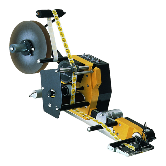
- Page 1 C C ollamat ollamat 3600/6600 3600/6600 ® Serial Communication RS232 Collamat Stralfors AG CH-4147 Aesch Pfeffingerring 201 Tel +41 61 756 28 28 Fax +41 61 756 29 29...
- Page 2 Index Page Important warnings Danger Indications Symbol descriptions Introduction General informations Prevention of accidents Noise suppression Technical description C3600 DIL-switches DIL-switch DIR DIL-switch TEST How to connect a goods scanner on C3600 Connection diagram C3600 Testmode Test software Technical description C6600 DIL-switches DIL-switch DIR DIL-switch TEST...
-
Page 3: Important Warnings
The labeler C3600/C6600 is exclusively determinated for labelling goods. ® The installation of a Collamat 3600/6600 has to be done by a trained specialist. For this you have to consider the national specific regulations of prevention of accidents mechanical stability... -
Page 4: Symbol Descriptions
Symbol descriptions ATTENTION ® Indicates danger of damaging the Collamat 6600 or other sy- stem components, with a potential consequential danger of injuries. DANGER Indicates an immediate hazard for persons. DANGER Shock hazard due to high voltage at component. DANGER Hazard due to high temperature component. -
Page 5: General Informations
The dispenser C6600 is shielded according to the CE directives. Only cables which are certificated by Collamat Stralfors AG may be used for connecting the dispenser to the peripheral units and the mains power. Additional peripheral units must be connected to the auxiliary mains terminal of the dispenser. - Page 6 Technical description C3600 SPEED PREDISP RESET FAULT 2AT 230V TEST 4AT 115V X102 X101 3 3 7 7 N PE Figure 1: Dispenser board Seite 5 / 32 5999.527-01A 25.11.98 WM...
- Page 7 DIL-switches The dispenser board contains two DIL-switches. These switches are used to select dif- ferent operating modes. The following table and figure 2 show the functions and the positions of the DIL-switches: Switch Function Turning direction of the motor Right Left TEST Labelingmode/ Testmode...
- Page 8 How to connect a goods scanner The goods scanners and incremental encoders are connected to the GSC1 and GSC2 connectors. Figure 3 shows the connection of the standard Collamat Stralfors AG IR goods scanner: G N D +12 V GSC1...
- Page 9 P1/P2 +12V GSC1 +12V GSC1 +12V Figure 5: Connection diagram Seite 8 / 32 5999.527-01A 25.11.98 WM...
-
Page 10: Test Mode
Testmode The firmware of the Collamat® 3600 has a standard test and diagnostic routine. If the DIL-switch TEST is switched on while turning the power on, the firmware starts the test and diagnostics routine. See also figure 2. In the testmode, the motor is started and stopped periodically with the speed, set on the SPEED potentiometer. -
Page 11: Test Software
Test software When the Collamat® 3600 is connected to the terminal, it must be switched on. At this moment the DIL-switch TEST must be set to on. The traction unit begins to turn with the speed set on the SPEED potentiometer. The terminal shows the following message: COLLAMAT 3600 V1.01... - Page 12 BUS-signal selftest The BUS-signal selftest tests all in- and outputs of the Collamat® signalbus. For this test a diagnostic connector (see figure 8) must be plugged into the busconnector X102 (left side). Attention: To avoid damage of peripheral units or sensors, all sensors and bus- cables must be removed from the connectors.
- Page 13 Potentiometer settings. Use spacebar to leave SPEED PRE. 0631 0057 0187 Firmware Version This test displays the firmware version number and its release date. >v Firmware Version COLLAMAT 3600 Version : V1.01 Date : 28. Nov. 1996 Seite 12 / 32 5999.527-01A 25.11.98 WM...
- Page 14 Technical description C6600 SPEED PREDISP X103 X106 RESET FAULT 2AT 230V TEST 4AT 115V X102 X101 3 3 7 7 N PE Figure 9: Dispenser board Seite 13 / 32 5999.527-01A 25.11.98 WM...
- Page 15 DIL-switches The dispenser board contains six DIL-switches. These switches are used to select diffe- rent operating modes. The following table and figure 10 show the functions and the positions of the DIL-switches: Switch Function Turning direction of the motor Right Left TEST Labelingmode/ Testmode...
- Page 16 DIL-switch NS ® This DIL-switch selects the Nonstopmode. In the Nonstopmode two Collamat 6600 can be used to work in a zero downtimemode. For further information to the Nonstop- mode, please read the chapter Nonstopmode.
- Page 17 How to connect a goods scanner The goods scanners and incremental encoders are connected to the GSC1 and GSC2 connectors. Figure 11 shows the connection of the standard Collamat Stralfors AG IR goods scanner: G N D +12V GSC1 GSC2 +12V Figure 11: Connection of the G &...
- Page 18 P1/P2 +12V GSC1 +12V GSC1 GSC2 +12V +12V Figure 14: Connection diagram Seite 17 / 32 5999.527-01A 25.11.98 WM...
- Page 19 In the testmode, the motor is started and stopped periodically with the speed, set on the ® SPEED potentiometer. If there are any labels threaded through the Collamat 6600, the labels will be dispensed periodically. The DATA-HOLD switch is supervised. Dependent to its position, the potentiometer values are scanned or stored.
- Page 20 ® When the Collamat 6600 is connected to the terminal, it must be switched on. At this moment the DIL-switch TEST must be set to on. The traction unit begins to turn with the speed set on the SPEED potentiometer. The terminal shows the following message: COLLAMAT 6600 V1.011...
- Page 21 Motor intervall test ® The Motor intervall test tests the labelling functions of the Collamat 6600. If a label web is threaded through the dispenser, labels will be dispensed periodically with the speed set on the SPEED potentiometer. >n Motor intervall test.
- Page 22 Figure 17 shows the schematic diagram of the diagnostic connector: + 1 2 V + 1 2 V R E A D Y F E E D L S C G S C 1 T C Y G S C 2 R E S O U T C L K R E S I N...
- Page 23 Serial No.: 0007 Potentiometer parameters ® On the Collamat 6600 the potentiometers can be programmed. With this function the working range of the potentiometers can be matched to a special labelling condition. To enable the potentiometer programmability, the DIL-switch TEST must be set to ON.
- Page 24 ® The function is called by pressing the O key. Then the Collamat 6600 gives the following message: >o Potentiometer parameters. Speed 30 m/min Predispensing 000 100 mm Position 100 mm Reset to factory settings SPACE : Exit Select function with the Keys S,P,O,R,SPACE The potentiometers can be selected with the S, P and O keys respectively.
- Page 25 Now the entered values are displayed and a request to store it in the EEPROM is asked. SPEED limits Upper limit : 20 Lower limit : 10 Store data ? Y/N Pressing the Y key stores the data. This function will be skipped with the N key. If the datas are stored the following message will be displayed: Updating EEPROM..OK >...
- Page 26 After pressing the ENTER key the following message will be displayed: New distance is : 157/100 mm : On : Off : Modify : Reset to factory settings ENTER : Keep SPACE : Exit Select function with the keys +,-,M,R,ENTER,SPACE Now the incremental encoder can be turned on by pressing the + key.
-
Page 27: Incremental Encoder
Incremental encoder The electrical connection of an incremental encoder is described in the chapter Connection of the goods scanners. The programming is described in the chapter Testmode. Now the mechanical attachment of the conveyor to the encoder will be described. If the speed measuring is done by an incremental encoder, the measured speed can be fine adjusted by ±10 % with the SPEED potentiometer. - Page 28 Serial Communication under Windows 3.1 und 3.11 Setup of the Windows Terminal programm Seite 27 / 32 5999.527-01A 25.11.98 WM...
- Page 29 After power on of the Collamat in testmode the following message will be shown: Seite 28 / 32 5999.527-01A 25.11.98 WM...
- Page 30 Serial Communication under Windows 95/98 Setup of Windows Terminal programms Hyperterm Seite 29 / 32 5999.527-01A 25.11.98 WM...
- Page 31 After power on of the Collamat in testmode the following message will be shown: Seite 30 / 32 5999.527-01A 25.11.98 WM...
-
Page 32: Glossary And Terms
Infra Red Light Emitting Diode not connected RS232 Standard serial data exchange protocol Signals ® ERROR Errorsignal caused by any error of the Collamat FEED Signal indicating the labelling process GrouND Goods SCanner IFEED Isolated FEED signal Label SCanner not connected... - Page 33 Rewinder: Device that takes the empty paperweb from the traction unit and rewinds it CE-Mark: Certification for the European market, means: Conformité Européenne ® Collamat : Brand name for a labeler built by Collamat Stralfors AG GSC: Goods SCanner Flap adapter with magnet: Adapter which moves down to the product during the labelling...
Need help?
Do you have a question about the 3600 and is the answer not in the manual?
Questions and answers