Table of Contents
Advertisement
Quick Links
Technical Handbook
Collamat C4300- / C7300- Series
Doc-ID: TH-C4300-C7300-EN
Release: 1.00/01/2013
These Operating Instructions and the Technical Handbook have to be read before start up, and before any work
are done on the machine.
This manual is a translated English version. The only mandatory
Technical Handbook for this product is the German version – signed
as the Original-/Reference-Version.
Contents
Advertisement
Table of Contents

Related Manuals for Collamat C4300 Series


Summary of Contents for Collamat C4300 Series
- Page 1 Contents Technical Handbook Collamat C4300- / C7300- Series Doc-ID: TH-C4300-C7300-EN This manual is a translated English version. The only mandatory Technical Handbook for this product is the German version – signed Release: 1.00/01/2013 as the Original-/Reference-Version. These Operating Instructions and the Technical Handbook have to be read before start up, and before any work...
- Page 2 Tel.: +41 (0) 61 756 28 - 28 Fax: +41 (0) 61 756 29 - 29 E-mail: info@collamat.ch Internet: www.collamat.ch Produced by: Collamat AG - ps 2012/11/26 V1.00 Prototype and Zero-Series -ps Internal message: use revision mode ONLY while updating the original (german reference) document (Überprüfen –...
-
Page 3: Table Of Contents
Personal protective equipment ........14 Industrial safety and special hazards ......15 Conduct in emergencies and accidents.......19 Safety equipment ............19 Assure against power on ..........20 Technical specifications .............21 Dimensions of Collamat C4300-C7300-Series....21 Condition at delivery ............22 3.2.1 Options ............24 Technical data..............25 Weight................26 Emissions..............26... - Page 4 Contents Symbols on the packaging...........31 Transport inspection.............32 Transport..............32 Packaging ..............33 Storage.................33 Installation and assembly............34 Safety ................34 Preparation..............35 Requirements of the installation location .....36 Assembly..............36 Mounting ..............38 Electrical connections ..........40 Wiring ................41 Inspection on conclusion of installation work ....41 Start-up and operation............42 Safety ................42 Adjustments ..............43 7.2.1...
- Page 5 Contents 8.1.1 Safety ............55 8.1.2 Connections „main-connecting terminals“...55 8.1.3 Cable input - Traction unit ......57 8.1.4 Connection „FUTURE-BUS“......57 8.1.5 Connection „Programming port“ ....58 8.1.6 Connection „external operator panel“...58 8.1.7 Connection „FEED-key“ .......58 8.1.8 Connection „motor controller“.......58 8.1.9 Connection „Transformer“ ......59 8.1.10 Connectoion „POWER input line“....59 8.1.11...
- Page 6 Contents 12.1 Abbreviations - general ..........76 12.2 Signal names ...............76 12.3 Terms - explanations............76 13 INDEX..................79 14 APPENDIXES ................81...
-
Page 7: General
General 1 General 1.1 Information to the Technical Handbook These operating instructions provide important information about using the machine. The prerequisite for safe work is the observation of all the safety information and operating instructions given here. In addition, for the use of the machine, the local accident prevention regulations and the general safety regulations are to be observed. -
Page 8: Symbols In The Instructions
General 1.2 Symbols in the instructions Warnings In these operating instructions, warnings are indicated by symbols. The warnings are introduced by words which indicate the extent of the hazard. Observe the warnings and act carefully, in order to avoid accidents, personal injury or material damage. DANGER! …... -
Page 9: Limitation Of Liability
General 1.3 Limitation of liability All statements and information in these operating instructions were compiled by taking into account the valid standards and regulations, the stat-of-the-art and our long years of expertise and experience. The manufacturer accepts no liability for damages due to: Not observing these operating instructions Use of the machine for purposes for which it was not intended... -
Page 10: Replacement Parts
General 1.5 Replacement parts WARNING! Danger of injury due to incorrect replacement parts! Incorrect or faulty replacement parts may cause damage, faulty function or total breakdown, as well as impairing safety. Therefore: – Only use original replacement parts made by the manufacturer. -
Page 11: Safety
2.1 Intended use The machine is exclusively designed for the intended purpose described here. The Collamat C4300/C7300 is a label dispensing unit for the application of labels, and is usually used in automated packaging lines for application of adhesive labels. -
Page 12: Responsibility Of The Operating Company
Safety 2.2 Responsibility of the operating company The machine will be used in a commercial area. The company operating the machine is therefore subject to the statutory obligations of industrial safety. In additions to the safety instructions for operation contained in these operating instructions, the valid regulations for safety, accident prevention and environmental protection for the area of use of the machine must be observed. -
Page 13: Operating Personnel
Safety 2.3 Operating personnel 2.3.1 Requirements WARNING! Danger of injury if insufficiently qualified! Incorrect use can cause considerable personal injury and material damage. Therefore: – All activities should only be carried out by the persons designated. The following qualification requirements for the various areas of activity are designated in the operating instructions: Instructed persons are those instructed by the operating company with regard... -
Page 14: Unauthorized Persons
Safety 2.3.2 Unauthorized persons WARNING! Danger to unauthorized persons! Unauthorized persons are unaware of the dangers which may result from the machine. Therefore: – Unauthorized persons must be kept away from the working area. – In case of doubt, speak to them and instruct them to leave the work area. -
Page 15: Industrial Safety And Special Hazards
Safety 2.5 Industrial safety and special hazards In the following section the residual risks will be stated, which result from the risk analysis. Observe the safety information and the warnings in this and other chapters in order to reduce hazards to health and avoid hazardous situations. - Page 16 Safety Danger symbols in the operating instruction In the operating instructions the following symbols are used in connection with safety information: Electrical current DANGER! Danger of death due to electrical current! There is direct danger of death on touching live components.
- Page 17 Safety Moving parts WARNING! Danger of injury due to moving parts! Driven, rotating or linearly moving components can cause extremely serious injuries! Therefore, during operation: – The presence of persons in the danger area or the immediate vicinity is strictly forbidden! –...
- Page 18 Safety Sharp paper edges BEWARE! Danger of injury due to sharp paper edges! Sharp paper edges can cause slight to moderate cuts. Therefore: – For all work, the prescribed personal protective equipment must be worn. – Always perform work with particular care and attention.
-
Page 19: Conduct In Emergencies And Accidents
Safety 2.6 Conduct in emergencies and accidents Preventive measures Always be prepared for accidents or fires! Keep first-aid equipment (first aid box, blankets etc.) and fire extinguishers so that they can easily be reached. Familiarize the personnel with first-aid and rescue equip- ment Keep access for emergency vehicles clear. -
Page 20: Assure Against Power On
Safety 2.8 Assure against power on Lock main control switch The main switch should be locked with a padlock to avoid an unwanted (unauthorized) power on - if there is a main switch within the safety chain. WARNING! Danger of life caused by unauthorized power Only with the mains control switch in position „0“... -
Page 21: Technical Specifications
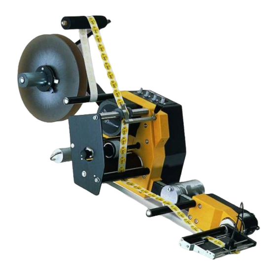
C4320 P / C 7320 P: 1 = 160mm 2 = 350 mm 3 = 965 … 1315 mm 4 = 518 … 648 mm = right version (see picture) = left version Measurements Collamat C4300/C7300 with 250/350mm –unwinder disks and short modular rail. -
Page 22: Condition At Delivery
Max. height dependent on size of rewinder disk size (518 or 648mm) Standard - applicator (Applicator depends on specification) 3.2 Condition at delivery Type designation Collamat Csxww D (according to Collamat AG „New classification 2008 - 2009 documentation„ ) C4310 / C4320 Collamat C4300 Series C7310 / C7320... - Page 23 The M8 good sensor plug „GSC“ on the side connection plate „SIGNALS“ is set by default to PNP-Sensors. The optional control line (Pin 2) is not connected (open). (standard) Please – only - use original good sensors from Collamat AG or ask a skilled labor how to connect another product/brand to your labeler. Future-Bus The 14-pin connector (left and right –...
-
Page 24: Options
Technical specifications 3.2.1 Options Side labeling set The optional „Lying Down Set“ will be used for installation where the product has to (optional) be labeled on the side. The optional „Side labeling set“ is made up of: Rewinder disc Ø150mm Unwinder dancer ring Pressure bearing for unwinder core Stabilization set for unwinder... -
Page 25: Technical Data
Technical specifications 3.3 Technical data Description Value Unit Connected load Supply voltage (AC) 115 / 230 VAC Phases 1~ Ph Frequency 60 / 50 Hz Maximum energy input 138/198 VA Internal mains fuse 5.0/2.5 AT External mains fuse 10 AT Protection type (digit 1 –... -
Page 26: Weight
Technical specifications 3.4 Weight Component Value Unit Traction unit (c4300) 10.9 kg with unwinder, modular rail + +4.2 applicator wide version (C4320) +0.8 Fast version (C7300) +1.2 kg 3.5 Emissions Description Value Unit Noise level, max. dB(A) 3.6 Performance values Description Value Unit... -
Page 27: Mounting
3.8 Mounting Description Clamp unit project specific 3.9 Identification plate Description Value Unit Cs3ww D* Type 10/2012 Year 115 / 230 VAC Voltage 5.0/2.5 AT Fuse 138/198 VA C4300 / C7300 00001 S/N (Serial-Number) * see chapter 3.2. -
Page 28: Construction And Function
Construction and function 4 Construction and function 4.1 Overview of components Dancer unwinder unit Unwinder disk (250/350mm) Traction unit Paper break (+ optional paper break sensor) Modular rail 30x30 Modular rail clamp 30x30 Applicator / Adapter 4.1.1 Side labeling - optional – Option: “Side labeling set”... -
Page 29: Variations
10=95 / 20=160 mm Direction L / R Branch P,F,C The Collamat C43ww / C73ww are available with the following applicator types: The different types of applicators are available in left or right completion (make). Applicator type... -
Page 30: Assembly Of The Unit
Construction and function 4.3 Assembly of the unit The central point of a Collamat C4300/C7300 unit is the traction unit housing. All Description peripheral equipment’s are connected to the traction unit housing (flange connectors). All peripheral parts are protected against corrosion (powder-coated / anodized). -
Page 31: Transport, Packaging And Storage
Transport, packaging and storage 5 Transport, packaging and storage 5.1 Safety information for transport Incorrect transport DANGER! Danger of the machine falling down or tipping over! The weight of the machine can cause injury and severe crushing! Therefore: – According to the size and weight of the machine, use a pallet on which the machine can be moved with a forklift truck. -
Page 32: Transport Inspection
Only in this way can claims for com- pensation be made within the applicable periods. 5.4 Transport Transport of the Collamat C4300/C7300 must be performed with a forklift truck or suitable straps. The lifting equipment must be designed for the weight of the machine. -
Page 33: Packaging
Transport, packaging and storage 5.5 Packaging Packaging The individual packages are packed according the transport conditions to be expected. Only environmentally compatible packaging material is used for packaging. The packaging should protect the individual components from transport damage, corrosion etc. until they are assembled. Therefore, do not destroy the packaging and only remove it shortly before assembly. -
Page 34: Installation And Assembly
Installation and assembly 6 Installation and assembly 6.1 Safety Basics WARNING! Danger of injury due to incorrect installation! Incorrect installation can cause serious injury or damage. Therefore: – All installation work may only be carried out by qualified personnel authorized and instructed by the operator. -
Page 35: Preparation
Installation and assembly Personnel The installation may only be performed by trained specialist personnel. Work on electrical equipment may only be carried out by qualified electricians. Personal protective equipment For all work during installation and start-up, the following personal protective equipment should be worn: Industrial safety clothing Protective gloves Safety footwear... -
Page 36: Requirements Of The Installation Location
Stability A Collamat C4300/C7300 mounted on a movable stand (adjustable or fix) has to be stable. The stability of the complete unit has to be guaranteed for an inclination of +/- 10° - see drawing below. - Page 37 Installation and assembly Unwinder unit Screw the unwinder unit to the traction unit housing. Use the attached four mounting screws (M4x16). The unwinder flange is located just above the side connection plate „POWER“. Modular rail and applicator If not already done - screw the square flange to the modular rail. Use the attached four mounting screws (M6x25).
-
Page 38: Mounting
Installation and assembly INFORMATION! The maximum load an operator of a Collamat C4300/C7300 unit is allowed to lift has been regulated in the corresponding directives EG 90/269/EWG respective 89/391/EWG. Label rolls - depending on outer diameter and paper width - can reach a total weight of up to 28kg. - Page 39 Installation and assembly Mounting – step by step Remove all transportation safety devices/locks and tapes. Bring unit to the designated location. Mount unit on the designated support (column, frame of another unit). Be sure the unit is aligned in parallel to the other units –...
-
Page 40: Electrical Connections
Remove the red fuse holder. Replace the fuses. Slide in the fuse holder. Close the cover. The power outlet plug is designated to connect Collamat C4300/C7300 peripherals ONLY! Plug in power cord (line cord) into a local power outlet. The power outlet has to be secured with 10A. -
Page 41: Wiring
Installation and assembly 6.7 Wiring For a fail-safe operation of the Collamat C4300/C7300 a few important point have to be remembered: Installation only by skilled labor. Ambient air temperature, dirt, dust, splash water Respect the specific mounting directions of the optional conveying equipment and other user specific subassemblies. -
Page 42: Start-Up And Operation
Start-up and operation 7 Start-up and operation 7.1 Safety Basics WARNING! Danger due to incorrect start-up! The start-up requires trained specialist personnel Errors in start-up can cause dangerous situations or considerable damage. Therefore: – Only have start-up work performed by the manufacturer's employees or his representatives, or by trained personnel. -
Page 43: Adjustments
Adjust the pressure roller (applicator) Align the label sensor receiver head Power-on the Collamat C4300/C7300 (mains switch) Adjustment of the height of the To get a perfect placement of the label on the good, the correct dispensing edge above the product adjustment of the height of the dispensing edge has an important influence. -
Page 44: Thread Up The Labels
Start-up and operation 7.2.1 Thread up the labels Load the labeler with the required paper web (see drawing below): Thread up: Unwind the paper web from the paper roll (a short distance). Remove all labels on this piece. Lift up the pressure roller from the traction roller by turning the button Wind the backing paper around the dispensing, traction roller and pressure roller to the rewinder core (see drawing below). -
Page 45: Rewinder Clutch Adjustment
Start-up and operation 7.3.2 Rewinder clutch adjustment The rewinder clutch power has been factory adjusted. The Clutch power adjustment readjustment of the clutch has to be done as following: Remove the rewinder core 1 after unscrewing the M5-screw 3. Adjust M8-screw 2 corresponding: screw in = firmer clutch screw out = weaker clutch 7.3.3 Modular rail... -
Page 46: Pressure Roller
Start-up and operation 7.3.4 Pressure roller Adjust position 1 Locking screw 2 Pressure roller REMARKS! The pressure roller includes a self aligning ball bearing – it’s therefore very important to set the pressure roller centric on the paper path. 7.3.5 Adapter tilt angle The tilt of the flap adapter in reference to the module-bar can be Adjust tilt of flap adapter changed accordingly:... -
Page 47: Adapter Front Pressure Roller
Start-up and operation 7.3.6 Adapter front pressure roller Adjustment The front pressure roller of the flap adapter can be adjusted according to label and goods: Horizontal adjustment with knurl nut (5). Vertical adjustment with hexagon nut (6). 7.3.7 Adapter – optical label scanner Adjustment The optical label scanner is built into the dispensing edge. -
Page 48: Adapter - Alternative Label Sensors
Start-up and operation Setting: Switch ON traction unit (Power ON), main switch lights up. Set potentiometer LABEL SCANNER for optical label scanning to zero. LED lamp on receiver (1) lights up. Move label gap (label web) right underneath marking (3) of the receiver head (1). Turn potentiometer LABEL SCANNER until LED lamp on receiver (1) goes off. -
Page 49: Unwinder - Adjustments
Start-up and operation 7.3.9 Unwinder - adjustments Dancer – spring force The spring force of the unwinder dancer arm can be easily adjusted. Don’t apply to much force to the dancer arm – just enough to bring the arm in its release position (top). Adjustment procedure: Press the turning-button (1) and turn it into the desired position (hold the dancer arm with the other hand during this procedure to feel the force... -
Page 50: Operation
Start-up and operation 7.4 Operation Operator panel The operator panel of the Collamat C4300/C7300 is used to adjust the labeling parameters. Use the potentiometers to adjust the speed, predispensing and label sensor, the main switch for power on/off and the feed key to eject a (test) label. -
Page 51: Parameter - Explanatory Notes
Start-up and operation SPEED The dispensing speed of the Collamat C4300/C7300 has to be equal to the speed of the conveyor belt (product flow speed). Adjust dispensing speed The speed adjustment will be done with the potentiometer „SPEED“ on the operator plate. -
Page 52: Labeling Parameter - Predispensing
Start-up and operation 7.5.2 Labeling parameter - Predispensing This function is used to adjust the predispensing parameter. The LABEL predispensing length (5) is the length between label sensor (3) and the PREDISPENSING leading edge of the label - placed on the dispensing edge (1). Adjust the predispensing Adjustement: use the potentiometer “LABEL PREDISPENSING”... -
Page 53: Jumper Adjustments
Start-up and operation Status LED The LSC receiver will be activated / deactivated by the corresponding ligth beam transmitting trough the light tube , trough the backingpaper resp. trough the backing paper and the label. The red LED on the receiver head indicates the output state of the LSC receiver. -
Page 54: Jumper - Test Functions
Start-up and operation 7.6.3 Jumper – Test functions Test run 1 – 3 These two jumpers are used to activate the test functions. Jumper 1 and 2: Position 2-3: normal labeling run (no test run) Jumper 1: Position 1-2 / Jumper 2: Position 2-3: Test function 1 activated Jumper 1: Position 2-3 / Jumper 2: Position 1-2: Test function 2 activated... -
Page 55: Connections + Buildup [Electronic]
WARNING! Take care while connecting sensors/actors to the Collamat C4300/C7300 inputs and outputs! Inappropriate handling on the Collamat C4300/C7300 electronic parts can destroy delicate components. Wiring jobs and repairs should be carried out by thepersons designated (see 3. Safety –... - Page 56 X11-1, X11-2, X11-3 All C4300-/C7300-inputs are NPN inputs! GOOD-SCANNER [!GSC] Use the standard good sensor from Collamat AG – or another NPN-sensor with open collector- or push-pull-output. !GSC = signal, 12V = voltage (10-30V), GND = ground potential This is the standard label scanner (receiver) input (from Collamat LABEL-SCANNER [!LSC] AG), if the fix adapter (without adapter board) is used –...
-
Page 57: Cable Input - Traction Unit
Connections + buildup [electronic] This galvanic isolated (opto coupler) output !RESO/RESO will be RESO-output [!RESO] used for debugging purposes (N.U.) This input will not be used (N.U.) GSC2-input [!GSC2] !GSC2 = signal, 12V = voltage (10-30V), GND = ground potential. 8.1.3 Cable input - Traction unit All cables going to / coming from the traction unit are guided Description... -
Page 58: Connection „Programming Port
Connections + buildup [electronic] 8.1.5 Connection „Programming port“ The port SV1 is used to program the microcontroller on the main board (specialist authorized by operating company). 8.1.6 Connection „external operator panel“ The port X103 is used to connect an external operator panel (in place of the original “potentiometer operator panel”) to the labeler. -
Page 59: Connection „Transformer
S/N: xxxx.xxxx POWER line cable with Swiss connector: S/N: xxxx.xxxx POWER line cable with USA connector: S/N: xxxx.xxxx Please use ONLY power cables from Collamat AG (with integrated ferrite core)! Cable color: Neutral (N): blue on X1-1-terminal (left) Phase (L):... -
Page 60: Connection „Main Power Switch
Connections + buildup [electronic] 8.1.12 Connection „Main Power switch“ The four cables from the POWER main switch (on the operator panel) will be connected on these terminals: Connection: Wire color: L-EIN brown N-EIN blue L-AUS brown-white N-AUS blue-white 8.1.13 Connection „FAN-output“ Optional terminal FAN (X13) –... -
Page 61: Motor Controller Hgd05
Connections + buildup [electronic] 8.2 Motor controller HGD05 The Status of the stepper motor controller is shown with the two LED’s LED FAU and LED HV – on the HGD05 board: LED-HV: - on = voltage ok - off = voltage to high / low LED-FAU: - on = thermal over load or voltage to high/low (see LED-HV) - off = controller has no error = active... -
Page 62: Applicator / Adapter
Applicator- / Adapter - Versions There are several different applicator types available for the Collamat C4300/C7300. Depending on the labeling job you have the choice of the following applicator types: The table below shows the applicator types and the matching applicator boards (electronics). -
Page 63: Connections „Applicator Terminals
Connections + buildup [electronic] 8.3.3 Connections „applicator terminals“ GS070B Standard applicator board : for all applicators – except: Magnet flap applicator (MFA), Air-Vacuum-Applicator (AVA), Blow applicator (BLA) Bus connection with the main board (inside of the traction unit): P1 - FUTURE-Bus (14-pin) connector P3 - blue shortcut bridge right (labeler right* –... -
Page 64: Connection „Applicator Pe
Connections + buildup [electronic] 8.3.4 Connection „Applicator PE“ PE Connection(s) This PE connection is identical for all applicator boards: [all applicator types] The PE screw terminal below the applicator board will be used to connect: the PE cable from the dispensing edge the PE cable from the main board (X4) - or the PE wire - from the AC-OUT terminal X2-3 via magnet- flap applicator power cable (if a magnet flap applicator is... -
Page 65: Software
Software 9 Software 9.1 Normal run Step by step: Power on the labeler, read the setting of the test jumpers, Application flow determine the corresponding application mode -> normal run or test run. Normal run: A low active GSC-signal on the !GSC input triggers the feeding of one label (GSC = good scanner. -
Page 66: Test Run 1
Software 9.2.1 Test run 1 Interval test run with adjusted dispensing speed (from SPEED-Potentiometer Application flow resp.from external operator panel). Feeding distance: 2000mm Pause: 1500 ms 9.2.2 Test run 2 Interval test run with adjusted dispensing speed (from SPEED- Application flow Potentiometer resp.from external operator panel). -
Page 67: Maintenance
Maintenance 10 Maintenance 10.1 Safety Basics WARNING! Danger of injury due to incorrectly performed maintenance work! Incorrect maintenance can cause serious injury or damage. Therefore: – All maintenance work may only be carried out by qualified personnel authorized and inst- ructed by the operator. - Page 68 Maintenance Electrical equipment DANGER! Danger of death due to electrical current! Contact with live components can cause danger of death. Electrically driven components can start to move without warning and cause extremely serious injuries. Therefore: – Before starting work, disconnect the power - supply and secure it against being switched on again.
- Page 69 Maintenance 10.2 Maintenance The following sections describe the maintenance work necessary for optimum and fault-free operation. The maintenance intervals are to be observed. If the regular checks show increased wear of individual components or functional assemblies, the operator must shorten the maintenance intervals according to the actual wear.
-
Page 70: Cleaning
Maintenance 10.3 Cleaning On occurrence of superficial dirt, proceed as follows: 1. Switch off the machine and secure against switching on again. 2. Remove dirt correctly. Note: Do not use aggressive cleaning agents. Absorb oil deposits with oil-absorbing materials (e.g. sawdust). -
Page 71: Faults, Repair And Maintenance Work
Faults, repair and maintenance work 11 Faults, repair and maintenance work This chapter describes the possible causes of faults, and the work needed to remedy these. If there is an increase of similar faults due to greater than average use, the maintenance intervals must be shortened according to the actual use. -
Page 72: Status Led
Faults, repair and maintenance work 11.4 Status LED Function Error (L3) Illuminates if +5V for logic is in range (ok) Fuse F2 (F1) (L2) Illuminates if +12V for sensors is in range (ok) Fuse F2 (F1) (L1) Illuminates if 77V for motor controller (C7300) is in range (ok) Fuse F3 (F1) Illuminates if 49V for motor controller (C4300) is in range (ok) Overheat, shortcut,... -
Page 73: Error-Output
Faults, repair and maintenance work 11.5 Error-output Problem Possible cause Troubleshooting Person No labels No labels on label roll (end of paper) Change label roll Operator The paper break is not on the paper web Position paper break Operator (Option paper break sensor) LSC problem Faulty adjustment of the label sensor. - Page 74 Faults, repair and maintenance work Fault Possible cause Remedy Execution by Incorrect or poor Collamat C4300/C7300 is not Correctly align Collamat. positioning of the correctly aligned with the goods Observe correct height Specialist labels conveyor adjustment. Poor label quality Try with new label roll Motor error Check paper web path –...
-
Page 75: Maintenance- And Repair- Works
(see also C4300- / C7300 - Spare Part Book) 11.8 Taking out of service and disposal A Collamat C4300/C7300 which can no longer be used should not be disposed of as an entire unit, but rather, should be dismantled into its component parts and recycled according to the type of materials. -
Page 76: Abbreviations, Signals, Terms
Board: An assembled control unit will be called print or PCB in this document CE-Sign: Product certificate - Conformity European Collamat: Brand name for the labeler unit from Collamat AG... - Page 77 300x30mm, 500 or 700mm in length - or user defined Mounting stand: several mounting stands are available (with corresponding clamping piece) l C4310 R: labeling unit type: Collamat C4300-serie with a max. paper width of 95mm in R = right version...
- Page 78 Abbreviations, signals, terms,… OOL: Out Of Label - see paper break / paper break check Operator Panel: used to controlled the labeling unit, used to set the system parameter like Labeling speed, label predispensing and label sensor. Paper break: the paper break is used to controlled break the paper moving (paper path from unwinder to dispensing edge) The (optional) paper break control is able to sense a paper break situation (OOL = Out Of Label) = control unit (see also optional OOL) –...
-
Page 79: Index
INDEX 13 INDEX Function ..............30 Abbreviations, signals, terms,… ......76 General ..............7 Accidents ............19 General ..............6 Adapter Inputs/Outputs........61 Goggles...............14 Adjustments............43 Anschlussplatte Daten........55 Hazard symbols ..........15 Anschlusswerte ..........25 Hazards...............15 Assembly ............36 Modular rail and adapter .........37 Identification plate..........27 Unwinder unit ..........37 Industrial safety...........15 Assembly of the unit ...........30 Industrial safety clothing ........14 Installation and assembly ........34... - Page 80 INDEX Performance values ........... 26 Safety ..............70 Personal Safety equipment ..........19 Störungsbeseitigung ........ 70, 71 Safety footwear ..........14 Personnel Sharp paper edges ..........18 remedy of faults..........70 Signs ..............18 Personnel Specialist personnel........... 13 Assembly............35 Standfestigkeit............
-
Page 81: Appendixes
APPENDIXES 14 APPENDIXES Register Description details CE – Declaration of conformity CE – Declaration of incorporation RoHS – Declaration of Conformity UL- / CSA - Conformity Lifting heavy loads Error checklist... - Page 82 - EN ISO 141121-1 Safety of machinery, Risk assessment. Principles. Remark: The CE-Declaration of Conformity is valid only – if the Collamat C4300/C7300 is safely mounted on a (Collamat AG) approved rack/stand. Issued in Reinach: 01. October 2012 Collamat AG – Bodenmattstrasse 34, CH-4153 Reinach, Switzerland...
- Page 83 Responsible person for the composition of all technical documents according to Appendix VII – chapter B of the Directive on Machinery 2006/42/EG is: Collamat AG, Paul Schneider, Bodenmattstrasse 34, CH-4153 Reinach, Switzerland Issued in Reinach: 01. October 2012 Collamat AG – Bodenmattstrasse 34, CH-4153 Reinach, Switzerland...
- Page 84 2003), if a „local“ professional waste management by the abroad reseller - according to WEEE2 – is not available. Collamat AG has taken all necessary steps to ensure the accuracy of this statement. The declaration is only binding for Collamat products that are purchased after the production date 13.02.2003.
- Page 85 Where/what: The status of this inquiry will be listed and continuous updated in the internal electronic part-list of the Collamat C4300- /C7300-series. The non electronic parts of the Collamat C4300/C7300-series are not covered in this study! Reinach, den 1. Oktober 2012 Collamat AG, Bodenmattstrasse 34, CH4153 Reinach, Switzerland ++41 61 7562828 - www.collamat.ch...
- Page 86 (near the ground) to the label dispenser Collamat C4300/C7300 (generally at working height / conveyor belt height). If label rolls of more than 15 kg are loaded onto a standard Collamat C4300/C7300 the unwinder unit must be supported with a stabilization set.
- Page 87 APPENDIXES Register F Error Checklist Labeler Serial Nbr: Collamat Typ: Unit identification: Nbr. …………………… C4310 R C4310 L C4320 R C4320 L C7310 R C7310 L C7320 R C7320 L Supply voltage (power): Supply frequency Hz: Temperature °C: Environment: Relative humidity %:...
Need help?
Do you have a question about the C4300 Series and is the answer not in the manual?
Questions and answers