
Related Manuals for Advantech IPC-5122


Summary of Contents for Advantech IPC-5122
- Page 1 User Manual IPC-5122 Desktop/Wallmount Chassis for MicroATX Motherboard 适用 Micro ATX 母板的桌上型 / 壁 挂式机箱 適用 Micro ATX 主機板的桌上型 / 壁掛式機箱...
- Page 2 No part of this manual may be reproduced, copied, translated, or transmitted in any form or by any means without the prior written permission of Advantech Co., Ltd. Information provided in this manual is intended to be accurate and reliable. How- ever, Advantech Co., Ltd.
- Page 3 In accordance with IEC 704-1:1982 specifications, the sound pressure level at the operator’s position does not exceed 70 dB (A). DISCLAIMER: These instructions are provided according to IEC 704-1 standards. Advantech disclaims all responsibility for the accuracy of any statements contained herein. IPC-5122 User Manual/ 用户手册...
- Page 4 设备无法正常工作,或您无法通过用户手册来使其正常工作; 设备跌落或者损坏; 设备有明显的外观破损。 请不要把设备放置在超出我们建议的温度范围的环境,即不要低于 0°C (32°F)或高于 60°C (140°F) ,否则可能会损坏设备。 注意:如果电池更换不正确,将有爆炸的危险。因此,只可以使用制造商推荐的 同一种或者同等型号的电池进行替换。请按照制造商的指示处理旧电池。 根据IEC 704-1:1982的规定,操作员所在位置的声压级不可高于70dB(A)。 免责声明:该安全指示符合 IEC 704-1 的要求。研华公司对其内容的准确性不承担任 何法律责任。 請仔細閱讀此安全操作說明。 請妥善保存此用戶手冊供日後參考。 用濕抹布清洗設備前,請從插座拔下電源線。請不要使用液體或去汙噴霧劑清洗 設備。 對於使用電源線的設備,設備周圍必須有容易接觸到的電源插座。 請不要在潮濕環境中使用設備。 請在安裝前確保設備放置在可靠的平面上,意外跌落可能會導致設備損壞。 設備外殼的開口是用於空氣對流,從而防止設備過熱。請不要覆蓋這些開口。 當您連接設備到電源插座上前,請確認電源插座的電壓是否符合要求。 請將電源線佈置在人們不易絆到的位置,並不要在電源線上覆蓋任何雜物。 請注意設備上的所有警告標識。 如果長時間不使用設備,請將其同電源插座斷開,避免設備被超標的電壓波動損 壞。 請不要讓任何液體流入通風口,以免引起火災或者短路。 請不要自行打開設備。為了確保您的安全,請由經過認證的工程師來打開設備。 如遇下列情況,請由專業人員來維修: 電源線或者插頭損壞; 設備內部有液體流入; IPC-5122 User Manual/ 用户手册...
- Page 5 Advantech has come to be known. Your satisfaction is our primary concern. Here is a guide to Advantech’s cus- tomer services.
- Page 6 Our dealers are well trained and ready to give you the support you need to get the most from your Advantech products. In fact, most problems reported are minor and can be easily solved over the phone.
- Page 7 Because of Advantech’s high quality-control standards and rigorous testing, most of our customers never need to use our repair service. If an Advantech product is defec- tive, it will be repaired or replaced at no charge during the warranty period. For out- of-warranty repairs, you will be billed according to the cost of replacement materials, service time and freight.
- Page 8 It should be free of marks and scratches and in perfect working order upon receipt. As you unpack the IPC-5122, check it for signs of ship- ping damage. (For example, damaged box, scratches, dents, etc.) If it is damaged or it fails to meet the specifications, notify our service department or your local sales representative immediately.
- Page 9 打開包裝時,用戶需確認包裝中含有下面所列各項: IPC-5122 主機殼 用戶手冊 質保卡 附件盒,包括橡膠墊腳、壁掛式安裝支架、一袋螺絲 (用于固定主機板、磁碟 機、橡膠墊腳、壁掛式安裝支架等) 如果其中任何一項缺失或者破損,請立即聯繫您的銷售商或銷售代表。裝貨前,我們 已全面仔細檢查過產品。因此您購買的產品應當是完好無損且運轉正常的。在您打開 產品的包裝時,請檢查是否有破損痕跡 (例如,包裝箱損壞,劃痕,凹痕等) 。如果 產品有破損或者不符合規格,請立即聯繫我們的服務部門或您的銷售商。同時也要通 知搬運人員。請保留包裝箱及包裝材料以備搬運人員檢查。檢查之後,我們會給您提 供維修或更換服務。 IPC-5122 User Manual/ 用户手册...
- Page 10 IPC-5122 User Manual/ 用户手册...
-
Page 11: Table Of Contents
Switch, Button, and I/O Interface/开关、按钮和I/O接口/開關、按鈕 和I/O介面 ..........18 3.1.2 LED Indicators for System Status/用于指示系统状态的LED指示灯/ 用於指示系統狀態的LED指示燈 ......19 Table 3.1: LED indicator functions/LED指示灯功能/LED指示燈功能 The Rear Panel/后面板/後窗........21 Figure 3.2 Rear Panel/后面板/後窗 ......21 Replacing the Cooling Fan/更换冷却风扇/更換冷卻風扇 ....22 Figure 3.3 Replacing the Cooling fan/更换冷却风扇/更換冷卻風扇 IPC-5122 User Manual/ 用户手册... - Page 12 4-Pin power connector/迷你4针电源接头 / 迷你4- pin 電源接頭 ......... 30 Table 4.2: RDUPG1, Redundant Power Connector/RDUPG1,冗余 电源接口/ RDUPG1,冗餘電源介面(IPC-5122 do not support redundant power supply / IPC-5122不支持冗 余电源 / IPC-5122不支援冗余电源) ..... 30 Table 4.3: ALMRST, Alarm Reset Connector/ALMRST,警报复位接 口/ALMRST,警報消除接頭 ...... 30 Table 4.4: FAN1, System Fan Connector/ FAN1,系统风扇接口/...
-
Page 13: General Information /概述/概述
Chapter General Information / 概述 / 概述... -
Page 14: Introduction/产品简介/產品簡介
Introduction/ 产品简介 / 產品簡介 Advantech’s IPC-5122 is an industrial-grade desktop/wall-mount chassis for Micro- ATX motherboards. It meets a variety of application needs for industries that operate 24-hours per day, like hospitals and convenience stores. This powerful computing platform is suitable for industrial automation, and factory management. A wide range of standard computing peripherals —... -
Page 15: Power Supply Options/电源选项/電源選項
-20 ~ 60 °C (-4 ~ 140 °F) 10 to 85% @ 40 °C (104 °F), 10 to 95% @ 40 °C (104 °F), Humidity/ 湿度 / 濕度 non-condensing/ 非凝結 non-condensing/ 非凝結 1 G rms Vibration/ 振动 / 振動 IPC-5122 User Manual/ 用户手册... -
Page 16: Dimension Diagram/产品尺寸/產品尺寸
Dimensions Diagram/ 产品尺寸 / 產品尺寸 unit: mm [inch] Figure 1.1 Dimension Diagram/ 产品尺寸 / 產品尺寸 IPC-5122 User Manual/ 用户手册... - Page 17 [inch] Figure 1.2 Installation/ 安装 / 安裝 IPC-5122 User Manual/ 用户手册...
- Page 18 IPC-5122 User Manual/ 用户手册...
-
Page 19: System Setup /系统安装 /統安裝
Chapter System Setup / 系统安 装 / 統安裝... -
Page 20: Removing The Side Cover/移除侧盖/ 移除側蓋
The following procedures instruct users on installing the motherboard, add-on cards, and disk drives into the IPC-5122. Please also refer to Appendix A, Exploded Dia- gram, for the detailed parts of IPC-5122. Note! Use caution when installing or operating the components with the chas- sis open. -
Page 21: Installing Microatx Motherboard/安装Microatx母板/安裝Microatx主機板
Installing a MicroATX Motherboard/安装MicroATX 母板 / 安裝 MicroATX 主機板 IPC-5122 supports a MicroATX motherboard with up to 4 x expansion slots. Follow the instructions below to install a MicroATX motherboard and/or some add-on cards: When installing a motherboard, first attach the motherboard I/O shielding onto the rear plate of IPC-5122 chassis. - Page 22 IPC-5122 支持 MicroATX 主機板,共有 4 個擴展插槽。請按照以下步驟的指導安裝 MicroATX 主機板或其它附加卡。 安裝主機板前,請先將主機板 I/O 彈片安裝至主機殼後面板,然後用螺絲將主機 板固定,如圖 2.2 所示。 將 20 pin ( 或 24 pin) ATX 電源連接器和 4 pin +12V 電源連接器連接至 Micro- ATX 主機板。 將主機殼上的 9 pin USB 線、電源開關線和系統重啟開關線連接至主機板。 將主機殼上的 HDD LED 線連接至主機板。 Figure 2.2 Installing a Motherboard/ 安装母板 / 安裝主機板...
-
Page 23: Installing Add-On Card/安装附加卡/安裝附加卡
Installing an Add-on Card/安装附加卡/安裝附加卡 IPC-5122 supports up to 4 x expansion cards depending on the embedded MicroATX specification. To install an add-on card, please proceed as follows: Select a PCI/PCIe slot for the add-on cards. Then, remove the corresponding I/ O bracket attached to the rear plate of the chassis. -
Page 24: Installing Disk Drives/安装磁盘驱动器/安裝磁碟架
Connect the suitable cables from MicroATX motherboard to the 3.5” HDD or slim ODD. Then plug the power connector into each disk drive. IPC-5122 支持 2 个 3.5” 磁盘驱动器 (1 个 3.5” 外置和 1 个 3.5” 内置)和一个薄 型光驱。请按照以下步骤的指导安装各种驱动器。 请按照以下步骤的指导安装 3.5”HDD 和薄型光驱,如图 2.4、2.5 所示。... -
Page 25: Hdd、Fdd和薄型Odd安装至托架/將3.5"Hdd、 Fdd和薄型Odd安裝至托架
Figure 2.4 Installing 3.5” HDD Disk Drive, FDD, and Slim ODD/ 将 3.5”HDD、FDD 和薄型 ODD 安装至托架 / 將 3.5”HDD、FDD 和薄型 ODD 安裝至托架 Figure 2.5 Installing the Disk Drive/ 安装磁盘驱动器 / 安裝磁碟機 IPC-5122 User Manual/ 用户手册... -
Page 26: Installing The Wall-Mount Bracket/安装壁挂式安装支架/安裝壁掛式安裝支 架
Figure 2.6 to simply fasten wall-mount brackets to the right edge and left edge of the bottom with the screws provided. 附件盒中提供了一对壁挂式安装支架。请参考图 2.6 用螺丝将支架固定在设备地步的 左右两侧。 附件盒中提供了一對壁掛式安裝支架。請參考圖 2.6 用螺絲將支架固定在設備地步的 左右兩側。 Figure 2.6 Installing the Wall-mount Brackets/ 安装壁挂式支架 / 安裝壁掛式支架 IPC-5122 User Manual/ 用户手册... - Page 27 Figure 2.7 Installing the Wall-mount Brackets/ 安装壁挂式支架 / 安裝壁掛式支架 IPC-5122 User Manual/ 用户手册...
- Page 28 IPC-5122 User Manual/ 用户手册...
-
Page 29: Operation /操作
Chapter Operation / 操作... -
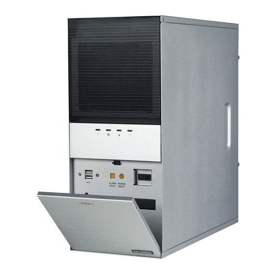
Page 30: The Front Panel/前面板
Dual USB ports: For connecting a wide range of USB devices for data transfer, backup or input. 瞬时电源开关:按下此按钮可接通或关闭系统电源。使用系统关机或按下此开关数秒 即可关闭系统的 ATX 电源。 系统复位按钮:按下此按钮可重启系统。 警告复位按钮:系统发生故障时 (如风扇故障或机箱内温度过高等) ,声音报警将被 启动。按下此按钮可停止报警器的报警声。 双 USB 接口:可连接多种 USB 设备,进行数据传输、备份或输入。 IPC-5122 User Manual/ 用户手册... -
Page 31: Led Indicators For System Status/用于指示系统状态的Led指示灯/ 用於指示系統狀態的Led指示燈
Normal/ 正常 机箱内温度 / (系统温度故障) / (CPU 温度故障) / 主機殼內溫度 異常 異常 (系統溫度故障) (CPU 溫度故障) Hard Disk/ 硬盘 / 硬碟 Hard disk drive Data access/ activity/ No light/ 灯不亮、 存取数据 / 硬盘状态 / 燈不亮 存取資料 硬碟狀態 IPC-5122 User Manual/ 用户手册... - Page 32 粉灯亮时,表示 CPU 冷却器发生故障。此时,报警器将被启动。按下报警复位按钮即 可停止报警声。用户需立即以完好风扇替换故障风扇。 温度 LED 红灯亮时,表示机箱内部温度过高 (高于 55° ) 。温度 LED 粉灯亮时,表示 ) 。此时,声音报警器将被启动。按下报警复位按钮即可停止 CPU 温度过高(高于 70° 报警声。用户需立即检查风扇滤网或 CPU 卡的温度以及机箱上部,确认机箱内的空气 流通良好、没有被灰尘等颗粒物阻塞。 注! CPU 冷却器或 CPU 温度是否可检测取决于 CPU 卡的设计。 HDD LED 闪烁时,表示 HDD 数据正在被访问。HDD LED 不亮时,表示 HDD 未活动。 IPC-5122 User Manual/ 用户手册...
-
Page 33: The Rear Panel/后面板/後窗
The rear plate includes six reserved 9-pin D-SUB openings and one optional 6 cm; 2.3 in fan. 后窗上预留了 6 个 9-pin D-SUB 开口和 1 个选配的 6 cm。 後窗上預留了 6 個 9-pin D-SUB 開口和 1 個選配的 6 cm。 Figure 3.2 Rear Panel/ 后面板 / 後窗 IPC-5122 User Manual/ 用户手册... -
Page 34: Replacing The Cooling Fan/更换冷却风扇/更換冷卻風扇
卸下风扇支架上的 4 个螺丝和风扇网罩上的 4 个螺丝,如图 3.5 所示。 更换风扇。 用卸下的螺丝固定新风扇和风扇网罩。 将风扇支架放回机箱并用卸下的 2 个大头螺丝进行固定,然后插上风扇电源插 头。 将侧盖放回原处并用螺丝固定好。 主機殼的前面板後側有一個冷卻風扇。風扇的氣流從前吹向後部,為系統提供了良好 的冷卻功能。請按照以下步驟的指導更換風扇: 移除側蓋。 拔下風扇電源插頭。 卸下風扇上部的 2 個螺絲,然後將其取出,如圖 3.4 所示。 卸下風扇支架上的 4 個螺絲和風扇網罩上的 4 個螺絲,如圖 3.5 所示。 更換風扇。 用卸下的螺絲固定新風扇和風扇網罩。 將風扇支架放回主機殼並用卸下的 2 個大頭螺絲進行固定,然後插上風扇電源插 頭。 將側蓋放回原處並用螺絲固定好。 IPC-5122 User Manual/ 用户手册... - Page 35 Figure 3.3 Replacing the Cooling fan/ 更换冷却风扇 / 更換冷卻風扇 Figure 3.4 Replacing the Cooling fan from the fan Bracket/从风扇支架上更换冷却 风扇 / 從風扇支架上更換冷卻風扇 IPC-5122 User Manual/ 用户手册...
-
Page 36: Changing The Filters/更换滤网/更換濾網
Put the fan filter back from the side of chassis. (see Figure 3.6) 滤网可以有效防止灰尘或颗粒物进入机箱并可延长系统使用寿命。建议用户定期清洗 或更换滤网。IPC-5122 机箱的滤网可清洗,位于风扇和铁网罩之间。请按照以下步骤 的指导清洗或更换滤网: 移除侧盖 取下位于铁网罩后部的滤网。 使用软刷清洁滤网或者清水冲洗灰尘然后晾干。 将滤网放回原处并用螺丝固定好,如图 3.6 所示。 濾網可以有效防止灰塵或顆粒物進入主機殼並可延長系統使用壽命。建議用戶定期清 洗或更換濾網。IPC-5122 主機殼的濾網可清洗,位於風扇和鐵網罩之間。請按照以下 步驟的指導清洗或更換濾網: 移除側蓋 取下位於鐵網罩後部的濾網。 使用軟刷清潔濾網或者清水沖洗灰塵然後晾乾。 將濾網放回原處並用螺絲固定好,如圖 3.6 所示。 Figure 3.5 Replacing the Filters/ 更换滤网 / 更換濾網 IPC-5122 User Manual/ 用户手册... -
Page 37: Replacing The Power Supply/更换电源/更換電源
Replacing the Power Supply/ 更换电源 / 更換電源 The IPC-5122 supports a single PS/2 power supply. To replace the power supply, please follow the instructions below. Unplug the power cord from the power supply and remove the side cover. Unplug the 20-pin (or 24-pin) ATX power connector and 4-pin +12 V power con- nector from the motherboard, as well as the power connectors from all disk drives. - Page 38 Figure 3.6 Replacing the Single Power Supply/ 更换单电源 / 更換單電源 IPC-5122 User Manual/ 用户手册...
-
Page 39: Alarm Board /报警板/告警板
Chapter Alarm Board /报警板/告 警板... -
Page 40: Alarm Board Layout/报警板布局/告警板佈局
ATX 電源模組發生故障; 任一冷卻風扇發生故障; 主機殼內部溫度過高; 按下前面板上的警報取消按鈕即可停止報警聲。 Alarm Board Layout/ 报警板布局 / 告警板佈局 The layout and detailed specification of the alarm board are given below: 报警板布局和详细规格如下图所示: 告警板佈局和詳細規格如下圖所示: Figure 4.1 Alarm Board Layout/ 报警板布局 / 告警板佈局 IPC-5122 User Manual/ 用户手册... -
Page 41: Alarm Board Specifications/报警板规格/報警板規格
2 個風扇介面口 1 個 “ 熱感測器 ” 介面 1 個 Power good ( 冗餘電源)接頭 ( IPC-5122 不支援冗餘電源 ) 1 個 “ 報警取消 ” 輸入介面 1 個 “HDD LED 指示燈 ” 介面 (連接 CPU 卡 / 主機板)... -
Page 42: Connectors Pin Definition/接口针脚定义/接頭 、跳線與Pin定義
Pin 4 +5 V Table 4.2: RDUPG1, Redundant Power Connector/RDUPG1, 冗余电源接口 / RDUPG1,冗餘電源介面 (IPC-5122 do not support redundant power supply / IPC-5122 不支持冗余电源 / IPC-5122 不支援冗余电源 ) Pin 1 Pin 2 PWR FAIL Table 4.3: ALMRST, Alarm Reset Connector/ALMRST,警报复位接口 / ALMRST,警報消除接頭... -
Page 43: Thermal Sensor/热传感器/熱感測器
Thermal Sensor/ 热传感器 / 熱感測器 The IPC-5122 is assembled with a thermal sensor located on the rear plate of the chassis (see Figure 4.2). IPC-5122 的热传感器位于机箱的后面板上。 (如图 4.2) IPC-5122 的溫度感應線位在機箱後窗 ( 如圖 4.2)。 Thermal sensor/热传感器 / 溫度感應線 Figure 4.2 Thermal Sensor Location/ 热传感器位置 / 熱感測器位置... - Page 44 IPC-5122 User Manual/ 用户手册...
-
Page 45: Exploded Diagram And Parts List/分解 图和部件列表/爆炸圖和零件表
Appendix Exploded Diagram and Parts List/分解图和部件 列表 / 爆炸圖和零件表... -
Page 46: Exploded Diagram And Parts List/分解图和部件列表/ 爆炸圖和零件表 . 34 Figure A.1 Exploded Diagram/分解图/爆炸圖
Exploded Diagram and Parts List/分解图和部件列 表 / 爆炸圖和零件表 Figure A.1 Exploded Diagram/ 分解图 / 爆炸圖 Table A.1: Parts List/ 部件列表 / 零件清單 Body of IPC-5122 chassis /机箱/機箱 I/O brackets on add-on card slots /附加卡槽挡片/附加卡槽擋片 Thermal sensor /热传感器/溫度感應線 Sensor holder /热传感器支架/溫度感應線支架... - Page 47 Table A.1: Parts List/ 部件列表 / 零件清單 Alarm board/报警板/ 告警板 Alarm board lens /报警版导光柱 / 告警板導光柱 Chassis cover /机箱侧板 / 機箱側板 IPC-5122 User Manual/ 用户手册...
- Page 48 No part of this publication may be reproduced in any form or by any means, electronic, photocopying, recording or otherwise, without prior written permis- sion from the publisher. All brand and product names are trademarks or registered trademarks of their respective companies. © Advantech Co., Ltd. 2021 www.advantech.com.cn 使用前请检查核实产品的规格。本手册仅作为参考。 产品规格如有变更,恕不另行通知。 未经研华公司书面许可,本手册中的所有内容不得通过任何途径以任何形式复制、翻...
Need help?
Do you have a question about the IPC-5122 and is the answer not in the manual?
Questions and answers