
Related Manuals for Advantech AIMB-742


Summary of Contents for Advantech AIMB-742
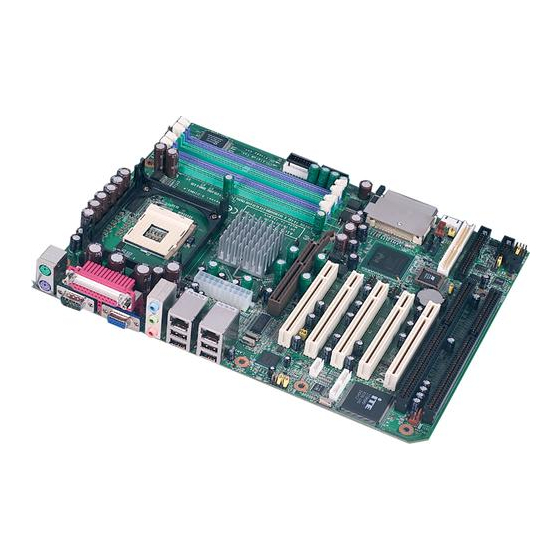
- Page 1 AIMB-742 Socket 478 Intel® Pentium® 4/Celeron® Industrial ATX Motherboard with DDR/AGP/ Dual Gigabit LAN (400/533/ 800 MHz FSB) User’s Manual...
-
Page 2: Copyright Notice
Copyright Notice This document is copyrighted, 2004, by Advantech Co., Ltd. All rights are reserved. Advantech Co., Ltd. reserves the right to make improve- ments to the products described in this manual at any time without notice. No part of this manual may be reproduced, copied, translated or transmit- ted in any form or by any means without the prior written permission of Advantech Co., Ltd. - Page 3 Advantech equipment is destined for the laboratory or the factory floor, you can be assured that your product will provide the reliability and ease of operation for which the name Advantech has come to be known. Your satisfaction is our primary concern. Here is a guide to Advantech’s customer services.
- Page 4 AIMB-742 User’s Manual...
-
Page 6: Product Warranty
Advantech assumes no liability under the terms of this warranty as a consequence of such events. If an Advantech product is defective, it will be repaired or replaced at no charge during the warranty period. For out-of-warranty repairs, you will be billed according to the cost of replacement materials, service time and freight. - Page 7 It should be free of marks and scratches and in perfect working order upon receipt. As you unpack the AIMB-742, check it for signs of shipping damage. (For example, damaged box, scratches, dents, etc.) If it is damaged or it fails to meet the specifications, notify our service department or your local sales representative immediately.
- Page 8 AIMB-742 User’s Manual viii...
-
Page 9: Table Of Contents
Board Layout: Jumper and Connector Locations....8 Figure 1.1:Jumper and Connector locations ....8 Figure 1.2:I/O Connectors ..........8 AIMB-742 Block Diagram..........9 Figure 1.3: AIMB-742 Block Diagram......9 Safety Precautions ............10 Jumper Settings ............... 11 1.8.1 How to set jumpers ............11 1.8.2... - Page 10 Figure 3.3:Advanced BIOS features screen....34 3.4.1 Hard Disk Boot Priority..........34 3.4.2 Virus Warning............... 34 3.4.3 CPU L1 & L2 Cache............. 34 3.4.4 Hyper-Threading Technology........34 3.4.5 Quick Power On Self Test ..........35 3.4.6 First/Second/Third Boot Device ........35 AIMB-742 User’s Manual...
- Page 11 3.4.7 Boot Other Device ............35 3.4.8 Swap Floppy Drive ............35 3.4.9 Boot UP Floppy Seek ........... 35 3.4.10 Boot Up NumLock Status..........35 3.4.11 Gate A20 Option............35 3.4.12 Typematic Rate Setting..........35 3.4.13 Typematic Rate (Chars/Sec) ......... 35 3.4.14 Typematic Delay (msec)..........
- Page 12 Current CPU Temperature ..........47 3.9.4 Current CPUFAN Speed..........47 3.9.5 VCORE, +1.5V, VCC3, +5V, +12V, -12V, -5V, VBAT(V), 5VSB(V)47 3.10 Spread Spectrum Control ..........48 Figure 3.12:Spread Spectrum Control screen ....48 3.10.1 CPU Clock Ratio ............48 AIMB-742 User’s Manual...
- Page 13 3.10.2 Spread Spectrum ............48 3.11 Password Setting ............. 48 3.12 Save & Exit Setup ............49 3.13 Exit Without Saving ............49 Chapter 4 Chipset Software Install Utility.....52 Before you begin ............. 52 Introduction ..............52 Windows XP Driver Setup..........53 Chapter 5 VGA Setup ............58 Introduction ..............
- Page 14 Table B.25:8-pin Alarm Board Connector (CN62) ..102 B.26 System I/O Ports............102 Table B.26:System I/O ports ........102 B.27 DMA Channel Assignments.......... 103 Table B.27:DMA channel assignments ...... 103 B.28 Interrupt Assignments ........... 104 Table B.28:Interrupt assignments ....... 104 AIMB-742 User’s Manual...
- Page 15 B.29 1st MB Memory Map............ 104 Table B.29:1st MB memory map ....... 104 B.30 PCI Bus Map ..............105 Table B.30:PCI bus map (for VE, E2 version) ... 105 Table B.31:PCI bus map (for VG, G2 version) ..105...
- Page 16 AIMB-742 User’s Manual...
- Page 17 General Information...
-
Page 18: Chapter 1 Hardware Configuration
It meets the requirements of a variety of applications where a commercial motherboard cannot fit. The AIMB-742 uses Intel's 865G chipset to support Intel's Socket 478 Pentium 4 and Celeron processor with 800/533/400 MHz front side bus. The dual channel DDR 400 SDRAM interface provides bottleneck free memory bandwidth up to 6.4GB/s. -
Page 19: Features
1.2 Features Standard ATX form factor with industrial features: AIMB-742 provides industrial features like long product life, reliable operation under wide temperature range, watchdog timer, CMOS backup functions, etc. PCI and ISA bus support: in addition to the 5 PCI slots, AIMB- 742 provides 2 ISA slots, allowing existing ISA legacy devices to be used in modern high performance computing system. -
Page 20: Memory
• Resolution: up to 1800x1440 @ 85Hz 1.3.5 Ethernet LAN • Supports single/dual 10/100Base-T networking or single/dual 10/100/ 1000Base-T Ethernet networking • Controller: Single 10/100Base-T: Intel 82562EZ Single 10/100/1000Base-T: Intel 82547GI (CSA) Dual 10/100/1000Base-T: Intel 82562EZ and Intel 82551QM AIMB-742 User’s Manual... -
Page 21: Industrial Features
• Board weight: 0.7 kg (1.68 lb) 1.4 Jumpers and Connectors Connectors on the AIMB-742 motherboard link it to external devices such as hard disk drives and a keyboard. In addition, the board has a num- ber of jumpers used to configure your system for your application. -
Page 22: Table 1.2:Connectors
USB port 2, 3 & LAN2 CN37 System FAN connector 2 CN44 CF socket (Optional), Master mode only CN55 Line Out, Mic IN connector CN56 CD IN (Audio input from CD-ROM) CN57 AUX IN connector CN58 MDM IN connector AIMB-742 User’s Manual... - Page 23 Table 1.2: Connectors CN59 FP AUDIO connector CN62 8-pin Alarm Board Connector CN63 USB port 6, 7 CN64 Case Open Serial ATA 0 Serial ATA 1 ATX1 ATX 12V Auxiliary power connector ATX2 ATX power connector...
-
Page 24: Board Layout: Jumper And Connector Locations
PCI2 ATX2 AGP1 CPU1 CN63 CN1 CN2 DIMM 1 DIMM 2 CN22 CN13 DIMM 3 DIMM 4 CN44 CN64 CN62 CN12 CN10 CN15 Figure 1.1: Jumper and Connector locations CN55 CN31 CN32 CN11 Figure 1.2: I/O Connectors AIMB-742 User’s Manual... -
Page 25: Aimb-742 Block Diagram
PCI to ISA Bridge 2 ATA 100 ITE8888 ports ATA 33/66/100 LAN2 Intel 2 SATA ports Intel 82801EB 150MB/s 82541/ ICH5 82551 8 USB Ports Audio Codec AC-97 LPC Bus Super IO BIOS Winbond W83627HF Figure 1.3: AIMB-742 Block Diagram... -
Page 26: Safety Precautions
The computer is provided with a battery-pow- ered Real-time Clock circuit. There is a danger of explosion if battery is incorrectly replaced. Replace only with same or equivalent type rec- ommended by the manufacturer. Discard used batteries according to manufacturer's instruc- tions. AIMB-742 User’s Manual... -
Page 27: Jumper Settings
* default setting 1.8.3 Watchdog timer output (J2) The AIMB-742 contains a watchdog timer that will reset the CPU or send a signal to IRQ11 in the event the CPU stops processing. This feature means the AIMB-742 will recover from a software failure or an EMI... -
Page 28: Table 1.4:Watchdog Timer Output (J2)
1.8.4 Riser card selection (J3 & J4) The AIMB-742 contains a riser card selection that enables the riser card function. While using 2U riser card, you should close pin 1 and pin 2 of J3 and J4 to activate the PCI slots on the riser card. -
Page 29: System Memory
1.9 System Memory The AIMB-742 has four sockets for 184-pin dual inline memory modules (DIMMs) in two separated memory channels. It can operate with single channel or dual channel modules. We recommend to use dual channel mode to provide optimized performance. -
Page 30: Memory Installation Procedures
The cache size in the Intel ® Pentium ® 4 processor is 256/512/1024 KB. In the Celeron CPU, the cache size is 128KB. 1.12 Processor Installation The AIMB-742 is designed for Intel Pentium® 4 processor/Celeron™ (socket 478) Note: Slim Heatsink &... - Page 31 with the corner where the lever is attached to the socket Step 3 : Lower the lever to its original position...
- Page 32 AIMB-742 User’s Manual...
- Page 33 Connecting Peripherals Chapter 2...
-
Page 34: Chapter 2 Connecting Peripherals
You can attach up to four IDE (Integrated Drive Electronics) drives to the AIMB-742’s built-in controller. The primary (CN1) and secondary (CN2) connectors can each accommodate two drives. Wire number 1 on the cable is red or blue and the other wires are gray. -
Page 35: Floppy Drive Connector (Cn3)
IDE can work as a slave device only and vice versa. 2.3 Floppy Drive Connector (CN3) You can attach up to two floppy disk drives to the AIMB-742's onboard controller. You can use 3.5" (720 KB, 1.44 MB) drives. -
Page 36: Usb Ports (Cn6/Cn63)
2.5 USB Ports (CN6/CN63) CN6/CN63 The AIMB-742 provides up to eight ports of USB (Universal Serial Bus) interface, which gives complete Plug & Play and hot swapping for up to 127 external devices.The USB interface complies with USB Specification Rev. 2.0 support transmission rate up to 480 Mbps and is fuse-protected. -
Page 37: Serial Ports (Com1 : Cn9; Com2 : Cn10 )
2.7 Serial Ports (COM1 : CN9; COM2 : CN10 ) CN10 The AIMB-742 offers two serial ports, CN9 as COM1 and CN10 as COM2. These ports can connect to serial devices, such as a mouse or a printer, or to a communications network. -
Page 38: External Keyboard Connector (Cn12)
2.9 External Keyboard Connector (CN12) CN12 In addition to the PS/2 mouse/keyboard connector on the AIMB-742's rear plate, there is also an extra onboard external keyboard connector. This gives system integrators greater flexibility in designing their sys- tems. 2.10 CPU Fan Connector (CN14) -
Page 39: Front Panel Connectors (Cn16, 17, 18, 19, 21&29)
2.12 Front Panel Connectors (CN16, 17, 18, 19, 21&29) There are several external switches to monitor and control the AIMB-742 CN16,17,18,19,21,29 2.12.1 Power LED and Keyboard Lock (CN16) CN16 is a 5-pin connector for the power on LED. Refer to Appendix B for detailed information on the pin assignments. -
Page 40: Hdd Led (Cn19)
2.12.6 SM Bus Connector (CN29) This connector is reserved for Advantech's SNMP-1000 HTTP/SNMP Remote System Manager. The SNMP-1000 allows users to monitor the internal voltages, temperature and fans from a remote computer through an Ethernet network. -
Page 41: Usb And Lan Ports (Cn31 And Cn32)
2.15 CF socket (CN44) The AIMB-742 provides one CF socket, which is compatible with type I and type II CF cards. The CF socket shares the same resource with sec- ondary IDE interface. CF card is only available for master mode. While setting CF as master, the other IDE device connected to secondary IDE can work as a slave device only. -
Page 42: Line Out, Mic In Connector (Cn55)
2.17 Audio input from CD-ROM (CD IN; CN56) The CD IN is a connector for CD-ROM to input the audio signal. 2.18 Aux Line-In connector (AUX IN; CN57) The connector is for audio device with Line-in connector. AIMB-742 User’s Manual... -
Page 43: Modem-In Connector (Mdm In; Cn58)
2.19 Modem-In connector (MDM IN; CN58) The connector is for modem with internal audio connector. 2.20 Front Panel audio connector (FP AUDIO; CN59) The FPAUDIO is a front panel audio connector compliant with Intel® Front Panel I/O Connectivity Design Guide. To direct the audio signal output to the rear audio ports, the 5 and 6 pins, 9 and 10 pins must be shorted by jumper to activate the rear panel audio function. -
Page 44: Case Open Connector (Cn64)
The 8-pin alarm board connector is for Advantech chassis with alarm board. 2.22 Case Open Connector (CN64) The 2-pin case open connector is for chassis with case open censor. While opening the case, the buzzer on motherboard will ring. 2.23 Serial ATA interface (SA0 and SA1) -
Page 45: Connecting To Snmp-1000 Remote Manager
2.25 Auxiliary 4-pin power connector (ATX1) To ensure the sufficiency of power supply for Pentium® 4 motherboard, one auxiliary 4 pin power connector is available on AIMB-742. It is strongly suggested to use ATX1 while the system is unstable. Chapter 2... - Page 46 AIMB-742 User’s Manual...
- Page 47 Award BIOS Setup Chapter 3...
-
Page 48: Chapter 3 Award Bios Setup
"CMOS checksum error..." display screen mes- sage appearing. Then enter the "Setup" screen to modify the data. If the "CMOS checksum error..."message appears again and again, please check to see if you need to replace the battery in your system. AIMB-742 User’s Manual... -
Page 49: Entering Setup
3.2 Entering Setup Turn on the computer and press <Del> to allow you to enter the BIOS setup. Figure 3.1: Award BIOS Setup initial screen 3.3 Standard CMOS Setup Choose the “Standard CMOS Features” option from the “Initial Setup Screen” menu, and the screen below will be displayed. This menu allows users to configure system components such as date, time, hard disk drive, floppy drive, display, and memory. -
Page 50: Advanced Bios Features
The “Advanced BIOS Features” screen appears when choosing the “Advanced BIOS Features” item from the “Initial Setup Screen” menu. It allows the user to configure the AIMB-742 according to his particular requirements. Below are some major items that are provided in the Advanced BIOS Features screen. -
Page 51: Quick Power On Self Test
3.4.5 Quick Power On Self Test Allows the system to skip certain tests while booting. This will decrease the time needed to boot the system. 3.4.6 First/Second/Third Boot Device The BIOS tries to load the OS with the devices in the sequence selected. Choices are: "Floppy", "LS120", "HDD-0", "SCSI", "CDROM", "HDD- 1", "HDD-2", "HDD-3", "ZIP100", "USB-FDD", "USB-ZIP", "USB- CDROM", "USB-HDD", "LAN", "Disabled". -
Page 52: Security Option
3.5 Advanced Chipset Features By choosing the “Advanced Chipset Features” option from the “Initial Setup Screen” menu, the screen below will be displayed. This sample screen contains the manufacturer’s default values for the AIMB-742, as shown in Figure 3-4: Note:... -
Page 53: Dram Timing Selectable
Figure 3.4: Advanced chipset features screen 3.5.1 DRAM Timing Selectable This item allows you to control the DRAM speed. The selections are "Manual" or "By SPD". 3.5.2 CAS Latency Time This controls the latency between DDR RAM read command and the time that the data actually becomes available. -
Page 54: System Bios Cacheable
Choose the first display interface to initiate while booting. The choice is "PCI Slot" or "Onboard". 3.5.13 On-Chip VGA User can disable onboard VGA controller by selecting "Disabled" 3.5.14 On-Chip Frame Buffer Size User can select frame buffer size. Option is :"1MB", "8MB" and "16MB". AIMB-742 User’s Manual... -
Page 55: Integrated Peripherals
3.6 Integrated Peripherals Figure 3.5: Integrated peripherals Figure 3.6: On-Chip IDE Device Chapter 3... -
Page 56: Ide Hdd Block Mode
3.6.4 Serial ATA Port0/Port1 Mode Select the mode for SATA port0 and SATA port1. The choices are "Pri- mary Master", "Primary Slave", "Secondary Master", "Secondary Slave", "SATA0 Master" and "SATA1 Master". Figure 3.7: Onboard Device AIMB-742 User’s Manual... -
Page 57: Usb Controller
3.6.5 USB Controller Select Enabled if your system contains a Universal Serial Bus (USB) con- troller and you have USB peripherals. The choices: "Enabled", "Dis- abled". 3.6.6 USB 2.0 Controller This entry is for disable/enable USB2.0 controller only. The BIOS itself may/may not have high speed USB support. -
Page 58: Onboard Fdc Controller
This field allows you to set the operation mode of the parallel port. The setting “Normal” allows normal speed operation, but in one direction only. “EPP” allows bidirectional parallel port operation at maximum speed. “ECP” allows the parallel port to operate in bi-directional mode AIMB-742 User’s Manual... -
Page 59: Epp Mode Select
and at a speed faster than the maximum data transfer rate. “ECP + EPP” allows normal speed operation in a two-way mode. 3.6.22 EPP Mode Select This field allows you to select EPP port type 1.7 or 1.9. The choices: "EPP1.9", "EPP1.7". -
Page 60: Acpi Function
If you choose “Instant-Off”, then pushing the ATX soft power switch but- ton once will switch the system to “system off” power mode. You can choose “Delay 4 sec.” If you do, then pushing the button for more than 4 AIMB-742 User’s Manual... -
Page 61: Cpu Thrm-Throttling
seconds will turn off the system, whereas pushing the button momentarily (for less than 4 seconds) will switch the system to “suspend” mode. 3.7.9 CPU THRM-Throttling This field allows you to select the CPU THRM-Throttling rate. The choices: "75.0%", "50.0%", and "25.0%". 3.7.10 Resume on LAN/PCI PME# To enabled or disable the function to resume the system by PCI card or LAN. -
Page 62: Pci Pirq [A-D]
"Auto(ESCD)" automatically configures all of the boot and Plug and Play devices but you must be using Windows 95 or above. 3.8.3 PCI/VGA Palette Snoop This is left at “Disabled.” 3.9 PC Health Status 3.9.1 CPU Warning Temperature AIMB-742 User’s Manual... -
Page 63: Figure 3.11:Pc Health Status Screen
This item will prevent the CPU from overheating. The choices are: "Dis- abled", "50C/122F", "53C/127F", "56C/133F", "60C/140F", "63C/145F", "66C/151F", "70C/158F". Figure 3.11: PC health status screen 3.9.2 Current System Temp This shows you the current temperature of system. 3.9.3 Current CPU Temperature This shows you the current CPU temperature. -
Page 64: Spread Spectrum Control
Press <Enter>. If the CMOS is good or if this option has been used to change the default password, the user is asked for the password stored in the CMOS. The screen will display the following message: AIMB-742 User’s Manual... -
Page 65: Save & Exit Setup
Please Confirm Your Password Enter the current password and press <Enter>. After pressing <Enter> (ROM password) or the current password (user-defined), you can change the password stored in the CMOS. The password must be no longer than eight (8) characters. Remember, to enable the password setting feature, you must first select either “Setup”... - Page 66 AIMB-742 User’s Manual...
- Page 67 Chipset Software Installation Utility Chapter 4...
-
Page 68: Chapter 4 Chipset Software Install Utility
To facilitate the installation of the enhanced display device drivers and utility software, you should read the instructions in this chapter carefully before you attempt installation. The device drivers for the AIMB-742 board are located on the software installation CD. The auto-run function of the driver CD will guide and link you to the utilities and device drivers under a Windows system. -
Page 69: Windows Xp Driver Setup
• Identification of Intel ® chipset components in the Device Manager. • Integrates superior video features. These include filtered sealing of 720 pixel DVD content, and MPEG-2 motion compensation for soft- ware DVD Note: This utility is used for the following versions of Windows system, and it has to be installed before installing all the other drivers: Windows 98SE... - Page 70 Click "Next" when you see the following message. Click "Yes" when you see the following message. AIMB-742 User’s Manual...
- Page 71 Click "Next" when you see the following message. When the following message appears, click "Finish" to complete the installation and restart Windows. Chapter 4...
- Page 72 AIMB-742 User’s Manual...
- Page 73 VGA Setup Chapter 5...
-
Page 74: Chapter 5 Vga Setup
Chapter 5 VGA Setup 5.1 Introduction The AIMB-742 has VGA onboard, you need to install the VGA driver to enable the function. The Intel® 865G Graphics Memory Controller Hub (the 865G GMCH) provides an integrated graphics accelerator delivering cost competitive 3D, 2D, and video capabilities. -
Page 75: Windows Xp Driver Setup
DVMT dynamically responds to system requirements, and application demands, by allocating the proper amount of display, texturing and buffer memory after the operating system has booted. For example, a 3D appli- cation when launched may require more vertex buffer memory to enhance the complexity of objects, or more texture memory to enhance the richness of the 3D environment. - Page 76 Windows XP. For other operating systems, please follow the on-screen installation guide Please click on "Next" to continue the installation AIMB-742 User’s Manual...
- Page 77 You will see a welcome window. Please chick on "Next" to con- tinue the installation. Click "Yes" when you see the following message. Chapter 5...
- Page 78 Click on "Yes" to continue the installation Click "Finish" to complete the installation and restart the computer now or later. AIMB-742 User’s Manual...
- Page 79 LAN Configuration Chapter 6...
-
Page 80: Chapter 6 Lan Configuration
Chapter 6 LAN Configuration 6.1 Introduction The AIMB-742 features the 32-bit 10/100/1000 Mbps Ethernet network interface. This interface supports bus mastering architecture and auto- negotiation features. Therefore standard twisted-pair cabling with RJ-45 connectors for 10 Mbps, 100 Mbps and 1000 Mbps connections can be used. -
Page 81: Installation
See Chapter 4 for information on installing the CSI utility. The AIMB-742's onboard Ethernet interface supports all major network operating systems. However, the installation procedure varies with differ- ent operating systems. In the following sections, refer to the one that pro- vides driver setup procedure for the operating system you are using. - Page 82 Select "I accept the terms in the license agreement" and click "Next" to continue. Click "Next" to continue. AIMB-742 User’s Manual...
- Page 83 Click "Install Software" to start the installation procedure. The driver will be installed automatically and the LAN function will be enabled after the installation. Chapter 6...
- Page 84 AIMB-742 User’s Manual...
- Page 85 Onboard Security Setup Chapter 7...
-
Page 86: Chapter 7 Onboard Security Setup
The AIMB-742's hardware monitor is designed with Winbond W83782D. Onboard security (OBS) functions monitor key hardware. They help you maintain your system's stability and durability. The AIMB-742 can moni- tor 5 sets of system positive voltages, 2 sets of system negative voltages, CPU cooling fan speed, and CPU temperature. -
Page 87: Windows Xp Driver Setup
7.2 Windows XP Driver Setup Insert the driver CD into your system's CD-ROM drive. In a few seconds, the software installation main menu appears, as shown in the following figure. Click on the "Install" button under the "OBS DRIVERS" heading. Click "Next"... - Page 88 Click "Next" when you see the following message. Click "Next" when you see the following message. AIMB-742 User’s Manual...
- Page 89 Click "Next" to continue. Click "Finish" when you see the following message. Chapter 7...
-
Page 90: Using The Obs Hardware Doctor Utility
From the desktop of Windows, click on "Start" and select "Pro- grams" , select "Winbond HWDoctor" and click "HWDOCTOR." It is recommended that you load the default values for all the OBS settings. However, if desired, you can establish new conditions for voltage, fan speed, and temperature. AIMB-742 User’s Manual... - Page 91 Chapter 7...
- Page 92 AIMB-742 User’s Manual...
- Page 93 Programming the Watchdog Timer Appendix A...
-
Page 94: Appendix A Programming The Watchdog Timer
Appendix A Programming the watchdog timer A.1 Programming the Watchdog Timer The AIMB-742's watchdog timer can be used to monitor system software operation and take corrective action if the software fails to function after the programmed period. This section describes the operation of the watchdog timer and how to program it. - Page 95 Unlock W83627H Select register of watchdog timer Enable the function of the watchdog timer Use the function of the watchdog time Lock W83627HF Appendix A...
- Page 96 (hex). This number decides how long the watchdog timer waits for strobe before generating an inter- rupt or reset signal. Writing a new value to this register can reset the timer to count with the new value. AIMB-742 User’s Manual...
-
Page 97: Example Program
F7 (hex) read/write Bit 6: Write 1 to enable key- board to reset the timer, 0 to disable.[default] Bit 5: Write 1 to generate a timeout signal immediately and automatically return to 0. [default=0] Bit 4: Read status of watch- dog timer, 1 means timer is ""time out""."... - Page 98 Enable watchdog timer and set 5 minutes as timeout interval ;----------------------------------------------------------- Mov dx,2eh ; unlock W83627H Mov al,87h Out dx,al Out dx,al ;----------------------------------------------------------- Mov al,07h ; Select registers of watchdog timer Out dx,al Mov al,08h Out dx,al AIMB-742 User’s Manual...
- Page 99 ;----------------------------------------------------------- Dec dx ; Enable the function of watchdog timer Mov al,30h Out dx,al Mov al,01h Out dx,al ;----------------------------------------------------------- Dec dx ; Set minute as counting unit Mov al,0f5h Out dx,al al,dx Or al,08h Out dx,al ;----------------------------------------------------------- Dec dx ; Set timeout interval as 5 minutes and start counting Mov al,0f6h Out dx,al Mov al,5...
- Page 100 Mov al,0f7h Out dx,al al,dx Or al,80h Out dx,al ;----------------------------------------------------------- Dec dx ; lock W83627HF Mov al,0aah Out dx,al Enable watchdog timer to be reset by keyboard ;----------------------------------------------------------- Mov dx,2eh ; unlock W83627H Mov al,87h Out dx,al AIMB-742 User’s Manual...
- Page 101 Out dx,al ;----------------------------------------------------------- Mov al,07h ; Select registers of watchdog timer Out dx,al Mov al,08h Out dx,al ;----------------------------------------------------------- Dec dx ; Enable the function of watchdog timer Mov al,30h Out dx,al Mov al,01h Out dx,al ;----------------------------------------------------------- Dec dx ; Enable watchdog timer to be strobed reset by keyboard Mov al,0f7h Out dx,al al,dx...
- Page 102 Out dx,al ;----------------------------------------------------------- Dec dx ; Generate a time-out signal Mov al,0f7h Out dx,al ;Write 1 to bit 5 of F7 register al,dx Or al,20h Out dx,al ;----------------------------------------------------------- Dec dx ; lock W83627HF Mov al,0aah Out dx,al AIMB-742 User’s Manual...
- Page 103 I/O Pin Assignments Appendix B...
-
Page 104: Appendix B Pin Assignments
SIGNAL GND DISK DMA REQUEST IO WRITE IO READ IO CHANNEL READY CSEL HDACKO* IRQ14 IDSC16- ADDR 1 PDIAG ADDR 0 ADDR 2 HARD DISK SELECT 0* 38 HARD DISK SELECT 1* IDE ACTIVE* * low active AIMB-742 User’s Manual... -
Page 105: Floppy Drive Connector (Cn3)
B.2 Floppy Drive Connector (CN3) Table B.2: Floppy drive connector (CN3) Signal Signal FDHDIN* FDEDIN* INDEX* MOTOR 0* DRIVE SELECT 1* DRIVE SELECT 0* MOTOR 1* DIRECTION* STEP* WRITE DATA* WRITE GATE* TRACK 0* WRITE PROTECT* READ DATA* HEAD SELECT* DISK CHANGE* * low active Appendix B... -
Page 106: Parallel Port Connector (Cn4)
B.3 Parallel Port Connector (CN4) Table B.3: Parallel port connector (CN4) Signal Signal STROBE* AUTOFD* INIT* SLCTINI* ACK* BUSY SLCT * low active AIMB-742 User’s Manual... -
Page 107: Usb Connector (Cn6 And Cn63)
B.4 USB Connector (CN6 and CN63) Table B.4: USB1/USB2 connector (CN6 and CN63) USB1 Signal USB2 Signal +5 V +5 V Chassis GND N/CA B.5 VGA Connector (CN7) Table B.5: VGA connector (CN7) Signal Signal GREEN BLUE H-SYNC V-SYNC Appendix B... -
Page 108: Com1/Com2 Rs-232 Serial Port (Cn9, Cn10)
B.6 COM1/COM2 RS-232 Serial Port (CN9, CN10) Table B.6: COM1/2 RS-232 serial port (CN9/10) Signal B.7 Keyboard and Mouse Connnector (CN11) AIMB-742 User’s Manual... -
Page 109: Table B.7:Keyboard And Mouse Connector (Cn11)
Table B.7: Keyboard and mouse connector (CN11) Signal KB DATA KB VCC KB CLK B.8 External Keyboard Connector (CN12) Table B.8: External keyboard connector (CN12) Signal DATA Appendix B... -
Page 110: Cpu/System Fan Power Conn (Cn14/15/37)
You can use an LED to indicate when the motherboard is on. Pin 1 of CN16 supplies the LED's power, and Pin 3 is the ground. Table B.10: Power LED and keylock conn (CN16) Function LED power (+5 V) AIMB-742 User’s Manual... -
Page 111: External Speaker Connector (Cn17)
B.11 External Speaker Connector (CN17) The motherboard has its own buzzer. You can also connect it to the exter- nal speaker on your computer chassis. Table B.11: External Speaker Connector (CN17) Function Buzzer Buzzer Speaker out B.12 Reset Connector (CN18) Table B.12: Reset connector (CN18) Signal RESET... -
Page 112: Hdd Led Connector (Cn19)
B.13 HDD LED Connector (CN19) Table B.13: HDD LED connector (CN19) Signal IDE LED (LED-) VCC (LED+) B.14 ATX Soft Power Switch (CN21) Table B.14: ATX soft power switch (CN21) Signal 5VSB PWR-BTN AIMB-742 User’s Manual... -
Page 113: H/W Monitor Alarm (Cn22)
B.15 H/W Monitor Alarm (CN22) Table B.15: H/W monitor alarm (CN22) Signal Enable OBS alarm Disable OBS alarm B.16 SM Bus Connector (CN29) Table B.16: SM Bus Connector (CN 29) Signal SMB_DATA SMB_CLK B.17 USB/LAN ports (CN31 and CN32) Table B.17: USB port Signal Signal Data0+... -
Page 114: Cf Socket (Cn44)
Table B.18: Ethernet 10/100Base-T RJ-45 port Signal Signal XMT+ XMT- RCV- RCV+ B.18 CF socket (CN44) Table B.19: CF socket (CN44) Signal Signal #CD1 #CS1 #CS1 #VS1 ATA SEL #IORD #IOWR INTRQ #CSEL #VS2 #RESET IORDY #INPACK #REG #DASP AIMB-742 User’s Manual... -
Page 115: Line Out, Mic In Connector (Cn55)
#PDIAG #IOIS16 #CD2 B.19 Line Out, Mic IN connector (CN55) Line Out MIC in B.20 Audio input from CD-ROM (CD IN; CN56) Table B.20: Audio in from CD-ROM (CD IN; CN56) Signal Signal CD_L CD_R Appendix B... -
Page 116: Aux Line-In Connector (Aux In; Cn57)
B.21 Aux Line-In connector (AUX IN; CN57) Table B.21: Aux Line-In connector (AUX IN; CN57) Signal Signal AUX_L AUX_R B.22 Modem-In connector (MDM IN; CN58) Table B.22: Modem-In connector (MDM IN; CN58) Signal Signal PHONE_IN MONOOUT AIMB-742 User’s Manual... -
Page 117: Front Panel Audio Connector (Fp Audio; Cn59)
B.23 Front Panel audio connector (FP AUDIO; CN59) Table B.23: Front audio conn (FP AUDIO; CN59) Signal Signal LOUT_RR MIC_BIAS LOUT_L LOUT_R LOUT_LL B.24 Case Open Connector (CN64) Table B.24: Case Open Connector (CN64) Signal CASEOP Appendix B... -
Page 118: 8-Pin Alarm Board Connector (Cn62)
022-023 Chipset address 040-05F 8254 timer 060-06F 8042 (keyboard controller) 070-07F Real-time clock, non-maskable interrupt (NMI) mask 080-09F DMA page register 0A0-0BF Interrupt controller 2 0C0-0DF DMA controller Clear math co-processor Reset math co-processor 0F8-0FF Math co-processor AIMB-742 User’s Manual... -
Page 119: Dma Channel Assignments
1F0-1F8 Fixed disk 200-207 Game I/O 278-27F Parallel printer port 2 (LPT3) 290-297 On-board hardware monitor 2F8-2FF Serial port 2 300-31F Prototype card 360-36F Reserved 378-37F Parallel printer port 1 (LPT2) 380-38F SDLC, bisynchronous 2 3A0-3AF Bisynchronous 1 3B0-3BF Monochrome display and printer adapter (LPT1) 3C0-3CF Reserved 3D0-3DF... -
Page 120: Interrupt Assignments
B.29 1st MB Memory Map Table B.29: 1st MB memory map Addr. range (Hex) Device E0000h - FFFFFh BIOS CC000h - DFFFFh Unused C0000h - CBFFFh VGA BIOS A0000h - BFFFFh Video Memory 00000h - 9FFFFh Base memory AIMB-742 User’s Manual... -
Page 121: B.30 Pci Bus Map
B.30 PCI Bus Map Table B.30: PCI bus map (for VE, E2 version) Function Signals: Device ID INT# pin Onboard LAN1 INT E Onboard LAN2 AD26 INT H GNT F REQ F Bridge AD22 GNT E REQ E PCI slot 1 AD31 INT B, C, D, A GNT A... - Page 122 AIMB-742 User’s Manual...
- Page 123 Appendix B...
- Page 124 AIMB-742 User’s Manual...
Need help?
Do you have a question about the AIMB-742 and is the answer not in the manual?
Questions and answers