
Subscribe to Our Youtube Channel
Related Manuals for Advantech AIMB-705


Summary of Contents for Advantech AIMB-705
- Page 1 User Manual AIMB-705 ® LGA1151 Intel Core i7/i5/i3 ATX with Dual display, Dual GbE LAN, SATAIII, USB3.0, DDR4...
- Page 2 No part of this manual may be reproduced, copied, translated or transmitted in any form or by any means without the prior written permission of Advantech Co., Ltd. Information provided in this manual is intended to be accurate and reliable. How- ever, Advantech Co., Ltd.
- Page 3 Whether your new Advantech equipment is destined for the labo- ratory or the factory floor, you can be assured that your product will provide the reliability and ease of operation for which the name Advantech has come to be known.
-
Page 4: Declaration Of Conformity
Caution! There is a danger of a new battery exploding if it is incorrectly installed. Do not attempt to recharge, force open, or heat the battery. Replace the battery only with the same or equivalent type recommended by the man- ufacturer. Discard used batteries according to the manufacturer's instructions. AIMB-705 User Manual... - Page 5 It should be free of marks and scratches and in perfect working order upon receipt. As you unpack the AIMB-705, check it for signs of ship- ping damage. (For example, damaged box, scratches, dents, etc.) If it is damaged or it fails to meet the specifications, notify our service department or your local sales representative immediately.
- Page 6 AIMB-705 User Manual...
-
Page 7: Table Of Contents
Board Layout: Jumper and Connector Locations........6 Figure 1.1 Jumper and Connector Locations....... 6 Figure 1.2 I/O View ..............6 AIMB-705 Block Diagram................7 Figure 1.3 AIMB-705 Block Diagram ........... 7 Safety Precautions ..................7 Jumper Settings ..................8 1.8.1 How to set jumpers ............... - Page 8 Auxiliary 4-pin connector (ATX12V1)............. 25 2.19 SPI Flash Connector (SPI_CN1) ............26 2.20 Low Pin Count Connector (LPC1)............27 Table 2.3: Advantech LPC Module List ........27 Chapter BIOS Operation ......... 29 Introduction ..................... 30 Figure 3.1 Main setup screen ........... 30 Entering BIOS Setup................
- Page 9 USB2.0 Header (USB910) ..............91 Table B.3: USB2.0 Header (USB56, USB78, USB1112)... 91 VGA Connector (VGA1) ................92 Table B.4: VGA Connector (VGA1) ........... 92 DVI Interface ................... 92 Table B.5: DVI-D Connector (DVI1/DVI2)........92 RS-232 and COM3 Interface..............93 AIMB-705 User Manual...
- Page 10 System I/O Ports................... 102 B.28 DMA Channel Assignments ..............103 Table B.29:DMA channel assignments........103 B.29 Interrupt Assignments ................103 Table B.30:Interrupt assignments..........103 B.30 1st MB Memory Map................103 Table B.31:1st MB memory map ..........103 AIMB-705 User Manual...
-
Page 11: Chapter 1 Hardware Configuration
Chapter Hardware Configuration... -
Page 12: Introduction
VGA and the DVI port at the same time (VGA only for VG sku). In addi- tion, the AIMB-705 has dual Gigabit Ethernet LAN (single GbE for VG sku) via dedi- cated PCIe x1 bus, which offers bandwidth of up to 500 MB/s, eliminating network bottlenecks. -
Page 13: Memory
USB 2.0 ports with transmission rates up to 480 Mbps. LPC: One LPC connector to support Advantech LPC modules, including PCA- COM232-00A1E and PCA-TPM-00B1E. GPIO: AIMB-705 supports 8-bit GPIO from super I/O for general purpose con- trol application. 1.3.4 Graphics Processor: Integrated Intel HD Graphics. -
Page 14: Jumpers And Connectors
Board weight: 0.7 kg (1.54 lb) Jumpers and Connectors Connectors on the AIMB-705 motherboard link it to external devices such as hard disk drives and a keyboard. In addition, the board has a number of jumpers that are used to configure your system for your application. - Page 15 Front panel audio pin header SPI_CN1 SPI flash card pin header SPDIF_OUT1 SPDIF audio output pin header GPIO1 8 bit GPIO from super I/O SMBUS1 SM bus from PCH Low pin count connector for Advantech TPM LPC and RS232 LPC1 modules. AIMB-705 User Manual...
-
Page 16: Board Layout: Jumper And Connector Locations
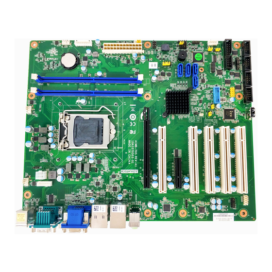
CPUFAN1 USB5 JCMOS1 USB3_12 CPU1 PCI1 PCI2 PCI3 PCI4 PCIEX4_1 ATX12V1 PCI5 SYSFAN2 PCIEX16_1 KBMS2 KBMS1 LANLED1 SPDIF_OUT1 AUDIO1 FPAUD1 LAN1_USB3_34 COM12 AUDIO2 VGA1+DVI1 LAN2_USB34 Figure 1.1 Jumper and Connector Locations AIMB-705G2-00A1E AIMB-705VG-00A1E Figure 1.2 I/O View AIMB-705 User Manual... -
Page 17: Aimb-705 Block Diagram
AIMB-705 Block Diagram Figure 1.3 AIMB-705 Block Diagram Safety Precautions Warning! Always completely disconnect the cord from your chassis whenever you work with the hardware. Do not make connections while the is on. Sensitive electronic components can be damaged by sudden surges. -
Page 18: Jumper Settings
1.8.3 Watchdog timer output (JWDT1) The AIMB-705 contains a watchdog timer that will reset the CPU. This feature means the AIMB-705 will recover from a software failure or an EMI problem. The JWDT1 jumper settings control the outcome of what the computer will do in the event the watchdog timer is tripped. -
Page 19: System Memory
2-3 closed * default setting AIMB-705 allows users to set USB between +5 V_DUAL and +5 V for onboard USB ports. When the jumper is set as +5 V, the board doesn't support wake up from S3 via keyboard or mouse. -
Page 20: Memory Installation Procedures
PCI Slot PCI1 PCI2 PCI3 PCI4 PCI5 IDSEL AD27 AD28 AD29 AD30 AD31 INTA INTB# INTA# INTD# INTC# INTB# INTB INTC# INTB# INTA# INTD# INTC# INTC INTD# INTC# INTB# INTA# INTD# INTD INTA# INTD# INTC# INTB# INTA# AIMB-705 User Manual... -
Page 21: Chapter 2 Connecting Peripherals
Chapter Connecting Peripherals... -
Page 22: Introduction
Parallel Port (LPT1) The parallel port is normally used to connect the motherboard to a printer. The AIMB- 705 includes an onboard parallel port, accessed through a 25-pin flat-cable connec- tor, LPT1. AIMB-705 User Manual... -
Page 23: Usb Ports And Lan Ports
(LAN1_USB3_34,LAN2_USB34, USB3_12, USB5, USB910) AIMB-705 provides 9 USB ports. LAN2_USB34, USB5, and USB910 are USB 2.0 ports supporting transmission rates up to 480 Mbps, and LAN1_USB3_34 and USB3_12 are USB 3.0 ports supporting transmission rate up to 5Gbps. The USB interface can be disabled in the system BIOS setup menu. -
Page 24: Vga Connector And Dvi-D Connector (Vga1 + Dvi1)
VGA Connector and DVI-D Connector (VGA1 + DVI1) The AIMB-705 includes both VGA and DVI-D interface that can drive conventional CRT and LCD displays (Only VGA interface on VG sku). Pin assignments of VGA1 and DVI1 are detailed in Appendix B. -
Page 25: Serial Ports (Com1, Com2, Com3, Com4, Com5 & Com6)
Serial Ports (COM1, COM2, COM3, COM4, COM5 & COM6) The AIMB-705 G2 sku offers six serial ports (two on the rear panel and four onboard). RS-232/422/485 mode is selectable by jumper and BIOS for COM3. These ports can connect to a serial mouse, printer or communications network. The IRQ and address ranges for those ports are fixed. -
Page 26: Ps/2 Keyboard And Mouse Connector (Kbms1/Kbms2)
(KBMS2) on the motherboard. This gives system integrators greater flexibility in designing their systems. CPU Fan Connector (CPUFAN1) If a fan is used, this connector supports cooling fans that draw up to 500 mA (6 W). AIMB-705 User Manual... -
Page 27: System Fan Connector (Sysfan1 And Sysfan2)
System FAN Connector (SYSFAN1 and SYSFAN2) If a fan is used, this connector supports cooling fans that draw up to 500 mA (6 W). AIMB-705 User Manual... -
Page 28: Front Panel Connectors (Jfp1, Jfp2 & Jfp3)
Front Panel Connectors (JFP1, JFP2 & JFP3) There are several external switches and LEDs to monitor and control the AIMB-705. JFP1+JFP2 JFP3 2.9.1 Power LED and Keyboard Lock (JFP3) JFP3 is a 5-pin connector for the power LED and keyboard lock. Refer to Appendix B for detailed information on the pin assignments. -
Page 29: External Speaker (Jfp2 Pins 1, 4, 7 & 10)
2.9.2 External Speaker (JFP2 pins 1, 4, 7 & 10) JFP2 is a 8-pin connector for an external speaker. The AIMB-705 provides an onboard buzzer as an alternative. To enable the buzzer, set pins 7-10 as closed. 2.9.3 HDD LED Connector (JFP2 pins 2 & 5) You can connect an LED to connector JFP2 to indicate when the HDD is active. -
Page 30: 8-Pin Alarm Board Connector (Volt1)
2.11 8-pin Alarm Board Connector (VOLT1) VOLT1 connects to the alarm board of Advantech chassis. The alarm board gives warnings if a supply or fan fails, chassis overheats, or the backplane malfunctions. AIMB-705 User Manual... -
Page 31: Case Open Connector (Jcase1)
2.12 Case Open Connector (JCASE1) JCASE1 is for chassis with a case open sensor. The buzzer on the motherboard sounds if the case is opened unexpectedly. AIMB-705 User Manual... -
Page 32: Front Panel Lan Indicator Connector (Lanled1)
2.13 Front Panel LAN Indicator Connector (LANLED1) Table 2.2: Front Panel LAN Indicator Connector LAN Mode Indicator LAN Link ON LAN Active Flash LAN Link Off AIMB-705 User Manual... -
Page 33: Serial Ata Interface (Sata0, Sata1, Sata2, Sata3)
2.14 Serial ATA Interface (SATA0, SATA1, SATA2, SATA3) AIMB-705 features four high performance serial ATA III interfaces (up to 600 MB/s) with long, thin, easy-to-run SATA cables. 2.15 PCI Slots (PCI1 ~ PCI5) The AIMB-705 provides five 32-bit / 33 MHz PCI slots. -
Page 34: Pcie X16 Expansion Slot (Pciex16_1)
2.16 PCIe x16 Expansion Slot (PCIEX16_1) The AIMB-705 provides one PCIe x16 slot for users to install an add-on peripheral card for extension requirements. 2.17 PCIe x4 Expansion Slot (PCIEX4_1) AIMB-705 User Manual... -
Page 35: Auxiliary 4-Pin Connector (Atx12V1)
To ensure the enough is supplied to the motherboard, one auxiliary 4-pin connector is available on the AIMB-705. ATX12V1 must be used to provide sufficient 12 V to ensure the stable operation of the system. Do not forget to connect the 24-pin EATXPWR1 plug;... -
Page 36: Spi Flash Connector (Spi_Cn1)
2.19 SPI Flash Connector (SPI_CN1) The SPI flash card (fixture) via the pin header of SPI_CN1 can flash the BIOS if AIMB-705 BIOS has crashed and can't be ed up (booted up). AIMB-705 User Manual... -
Page 37: Low Pin Count Connector (Lpc1)
2.20 Low Pin Count Connector (LPC1) LPC connector on AIMB-705 is reserved for Advantech LPC modules. Table 2.3: Advantech LPC Module List Description PCA-TPM-00B1E TPM 2.0 Module PCA-COM232-00A1E 4-port RS-232 LPC module AIMB-705 User Manual... - Page 38 AIMB-705 User Manual...
-
Page 39: Bios Operation
Chapter BIOS Operation... -
Page 40: Introduction
The Setup Utility uses a number of menus for making changes and turning the specific features on or off. This chapter describes the basic navigation of the AIMB-705 setup screens. Figure 3.1 Main setup screen AMI’s BIOS ROM has a built-in Setup program that allows users to modify the... -
Page 41: Entering Bios Setup
System Date using the <Arrow> keys. Enter new values through the keyboard. Press the <Tab> key or the <Arrow> keys to move between fields. The date must be entered in MM/DD/YY format. The time must be entered in HH:MM:SS format. AIMB-705 User Manual... -
Page 42: Advanced Bios Features Setup
3.2.2 Advanced BIOS Features Setup Select the Advanced tab from the AIMB-705 setup screen to enter the Advanced BIOS setup screen. You can select any of the items in the left frame of the screen, such as CPU configuration, to go to the sub menu for that item. -
Page 43: Figure 3.4 Platform Misc Configuration
Figure 3.4 Platform Misc Configuration Platform Misc Configuration – Native PCIE Enable PCI Express Native Support Enable/Disable. This is only available in Vista. – Native ASPM On enable, Vista will control the ASPM support for the device. AIMB-705 User Manual... -
Page 44: Figure 3.5 Cpu Configuration
Active Processor Core Use this item to select the number of processor cores you want to activate when you are using a dual or quad core processor. "Enable or Disable" CPA advanced encryption standard instruction. AIMB-705 User Manual... - Page 45 3.2.2.3 Power & Performance Boot Performance Select the performance state that the BIOS will set before OS handoff. Intel(R) Speedstep(tm) Allows more than two frequency ranges to be supported. Turbo Mode Turbo mode. AIMB-705 User Manual...
-
Page 46: Figure 3.6 Pch-Fw Configuration
C states Intel C states setting for power saving. 3.2.2.4 PCH-FW Configuration Figure 3.6 PCH-FW Configuration PCH-FW Version PCH-FW page shows Intel ME FW information. AIMB-705 User Manual... -
Page 47: Figure 3.7 Tpm Settings
3.2.2.5 Trusted Computing Figure 3.7 TPM Settings TPM Support “Enable or Disable” TPM Support. You can purchase Advantech LPC TPM mod- ule to enable TPM function. P/N: PCA-TPM-00A1E. AIMB-705 User Manual... -
Page 48: Figure 3.8 Acpi Settings
ACPI Sleep State Select S3 or disable suspend. Lock Legacy Resources "Enable or Disable" Lock Legacy Resources. S3 Video Repost "Enable or Disable" S3 Video Repost. PowerOn by Modem "Enable and Disable" PowerOn by Modem. AIMB-705 User Manual... -
Page 49: Figure 3.9 Smart Settings
3.2.2.7 SMART Settings Figure 3.9 SMART Settings SMART Self Test "Enable or Disable" SMART Self Test on all HDDs during POST. AIMB-705 User Manual... -
Page 50: Figure 3.10Super Io Configuration
3.2.2.8 Super IO Configuration Figure 3.10 Super IO Configuration Figure 3.11 Serial Port 1 Configuration AIMB-705 User Manual... -
Page 51: Figure 3.12Parallel Configuration
Parallel Port To "Enable or Disable" Parallel Port. – Change Settings To select an optimal setting for parallel port. – Device Mode Parallel port could be selected as "ECP and EPP 1.9 Mode" and other set- tings. AIMB-705 User Manual... -
Page 52: Figure 3.13Pc Health Status
CPUFAN Smartfan Setting “Enable or Disable” CPUFAN Mode to SMART FAN setting. SYSFAN1 Smartfan Setting "Enable or Disable" SYSFAN Mode to SMART FAN setting. SYSFAN2 Smartfan Setting Enable or Disable SYSFAN Mode to SMART FAN setting. AIMB-705 User Manual... -
Page 53: Figure 3.14Super Io Configuration
3.2.2.10 Second Super IO Configuration Figure 3.14 Super IO Configuration AIMB-705 G2 sku supports 2nd super IO for COM 3~6, this page of BIOS menu is to set respective serial port configuration. Figure 3.15 Serial Port 3 Configuration AIMB-705 User Manual... -
Page 54: Figure 3.16Serial Port 4 Configuration
Change Settings To select an optimal setting for serial port 3. – Change Device Mode Settings Can be selected to Standard Serial Port Mode (RS-232), RS-485 Half Duplex, or RS-422 Full Duplex. Figure 3.16 Serial Port 4 Configuration AIMB-705 User Manual... -
Page 55: Figure 3.17Serial Port 5 Configuration
Figure 3.17 Serial Port 5 Configuration Figure 3.18 Serial Port 6 Configuration AIMB-705 User Manual... -
Page 56: Figure 3.19S5 Rtc Wake Settings
To select an optimal setting for serial port 6. 3.2.2.11 S5 RTC Wake Settings Figure 3.19 S5 RTC Wake Settings Wake system with Fixed Time To "Enable or Disable" System wake on alarm event. The system will wake on the hr:min:sec as specified. AIMB-705 User Manual... -
Page 57: Figure 3.20Serial Port Console Redirection
Console Redirection Enable or Disable. Legacy Console Redirection – Legacy Console Redirection Settings Legacy Console Redirection Settings. Serial Port for Out-of-Band Management/ Windows Emergency Manage- ment services (EMS) – Console Redirection Console Redirection Enable or Disable. AIMB-705 User Manual... -
Page 58: Figure 3.21 Intel Txt Information
3.2.2.13 Intel TXT Information Figure 3.21 Intel TXT Information AIMB-705 User Manual... -
Page 59: Figure 3.22Pci Subsystem Settings
3.2.2.14 PCI Subsystem Settings Figure 3.22 PCI Subsystem Settings PCI Common Settings PCI Latency Timer Value to be programed into PCI Latency Timer Register. VGA Palette Snoop "Enable or Disable" VGA palette registers snooping. AIMB-705 User Manual... -
Page 60: Figure 3.23Csm Configuration
Controls the execution of UEFI and Legacy Storage OpROM. – Video Controls the execution of UEFI and Legacy Video OpROM. – Other PCI devices Determines OpROM execution policy for devices other than Network, Stor- age or Video. AIMB-705 User Manual... -
Page 61: Figure 3.24Usb Configuration
Hub descriptor. Mass Storage Devices Mass storage device emulation type. "Auto" enumerates device according to their media format. Optical drives are emulated as 'CDROM', drives with no media will be emulated according to a drive type. AIMB-705 User Manual... -
Page 62: Chipset
3.2.3 Chipset Figure 3.25 Chipset This page provides information of the chipset on AIMB-705. 3.2.3.1 System Agent (SA) Configuration Figure 3.26 System Agent (SA) Configuration VT-d "Enable or Disable" VT-d function. AIMB-705 User Manual... -
Page 63: Figure 3.27Graphics Configuration
Figure 3.27 Graphics Configuration Figure 3.28 External Gfx Card Primary Display Configuration Primary Display "Auto or IGFX or PEG or PCI or SG" optimal to Primary Display. Primary PEG Select PEG0/PEG1/PEG2/PEG3 graphics device should be Primary PEG. AIMB-705 User Manual... -
Page 64: Figure 3.29Lcd Control
PCIE18/ PCIE19 of D27: F0/ F1/ F2/ F3, Graphics device should be primary PCIE. Internal Graphics "Auto or Disable or Enable" Internal Graphics. Figure 3.29 LCD Control LCD Control Select Primary IGFX Boot Display as "VBIOS Default, DVI1, or CRT". AIMB-705 User Manual... - Page 65 3.2.3.3 PEG Port Configuration Enable Root Port Enable or disable the root port. Max Link speed Configure PEG 0:1:0 max speed. Detect Non-compliance device Detect Non-Compliance PCI express Device in PEG. AIMB-705 User Manual...
- Page 66 3.2.3.4 Memory Configuration Maximum Memory Frequency Maximum memory frequency selections in Mhz. AIMB-705 User Manual...
-
Page 67: Figure 3.30Pch-Io Configuration
"Enable or Disable" PCIE to wake the system from S5. High Precision timer "Enable or Disable" the high precision event timer. Restore AC Power Loss "Power off or Power on" or Last State to restore AC Power Loss. AIMB-705 User Manual... - Page 68 3.2.3.6 PCI Express Configuration AIMB-705 User Manual...
- Page 69 Select "Auto, Gen1, Gen2, Gen3" for PCIe Speed Advanced Error Reporting "Enable or Disable" advanced error reporting Detect Non-Compliance Device Detect Non-Compliance PCI Express Device. If enable, it will take more time at POST time. AIMB-705 User Manual...
-
Page 70: Figure 3.31Sata Configuration
Hot Plug "Enable or Disable" SATA Hot-Plug Spin up Device "Enable or Disable" spin up device SATA Device Type To identify the SATA that is connected to a Solid State or Hard Disk Drive. AIMB-705 User Manual... -
Page 71: Figure 3.32Usb Configuration
3.2.3.8 USB Configuration Figure 3.32 USB Configuration XHCI Disable Compliance mode Options to disable compliance mode. Default is FALSE enable compliance mode. Set TRUE to disable compliance mode. AIMB-705 User Manual... -
Page 72: Figure 3.33Hd Audio Configuration
3.2.3.9 HD Audio Configuration Figure 3.33 HD Audio Configuration HD Audio Control detection of the HD-Audio device. Disable = HDA will be unconditionally disabled. Enable = HDA will be unconditionally enabled. AIMB-705 User Manual... -
Page 73: Security
Security Figure 3.34 Security Select Security Setup from the AIMB-705 Setup main BIOS setup menu. All Security Setup options, such as password protection is described in this section. To access the sub menu for the following items, select the item and press <Enter>. -
Page 74: Boot
“On or Off” power-on state for the NumLock. Quiet Boot "Enable or Disable" Quiet Boot option. Boot Option #1/2 Sets the boot order. Hard Drive BBS Priorities Set the order of the legacy devices on this group. AIMB-705 User Manual... -
Page 75: Save & Exit
Select Exit Discarding Changes from the Exit menu and press <Enter>. The following message appears: Quit without saving? [Yes] [No] Select Yes to discard changes and exit. Discard Changes Select Discard Changes from the Exit menu and press <Enter>. AIMB-705 User Manual... - Page 76 AIMB-705 User Manual...
-
Page 77: Chapter 4 Chipset Software Installation Utility
Chapter Chipset Software Installation Utility... -
Page 78: Before You Begin
Before you begin To facilitate the installation of the enhanced display drivers and utility software, read the instructions in this chapter carefully. The drivers for the AIMB-705 are located on the software installation DVD. Note! The files on the software installation DVD are compressed. Do not attempt to install the drivers by copying the files manually. -
Page 79: Windows 10 / Windows 8.1 / Windows 7 Driver Setup
Insert the driver DVD into your system's DVD-ROM drive. You can see the driver folders items. Move the mouse cursor over the folder "01_Chipset". In CSI folder, you can click find an executable file to complete the implementation of the driver. Click setup to execute program. AIMB-705 User Manual... - Page 80 AIMB-705 User Manual...
-
Page 81: Chapter 5 Integrated Graphic Device Setup
Chapter Integrated Graphic Device Setup... -
Page 82: Introduction
Insert the driver DVD into your system's DVD-ROM drive where you can see the driver folders items. Navigate to the "02_Graphics" folder and click the executable file to complete the installation of the drivers for Windows 7/8.1/10. AIMB-705 User Manual... -
Page 83: Chapter 6 Lan Configuration
Chapter LAN Configuration... -
Page 84: Introduction
Introduction The AIMB-705 is equipped up to two Gigabit Ethernet LANs via dedicated PCI Express x1 lanes (Intel I219-V (LAN1) and I211-AT (LAN2)) that offer bandwidth of up to 500 MB/sec, eliminating the bottleneck of network data flow and incorporating Gigabit Ethernet at 1000 Mbps. -
Page 85: Chapter 7 Intel Me
Chapter Intel ME... -
Page 86: Introduction
If the Intel® Management Engine (Intel® ME) driver has not been suc- cessfully installed, you may see an error on a "PCI Simple Communica- tions Controller" in Device Manager. If you use Win7 OS, please install "Win7 update" folder first, and then reboot system to install ME driver. AIMB-705 User Manual... -
Page 87: Chapter 8 Intel Usb 3.0
Chapter Intel USB 3.0... -
Page 88: Introduction
Introduction AIMB-705 provides Intel® USB 3.0 and the data transfer rate of USB3.0 (5Gb/s) is 10 times to USB2.0 (480 Mbps). Installation Insert the driver DVD into your system’s DVD-ROM drive. Navigate to the "05_USB3.0" to install the driver. AIMB-705 User Manual... -
Page 89: Chapter 9 Hd Audio
Chapter HD Audio... -
Page 90: Introduction
Introduction AIMB-705 is equipped with Realtek ALC892 Audio chip. It provides "Line-out" & "Microphone" two ports for any related applications. Installation The driver is on the DVD in the "06_Others" folder. Navigate to the directory and fol- low the installation guide to install the driver and utility. -
Page 91: Appendix A Programming The Watchdog Timer
Appendix Programming the Watchdog Timer... -
Page 92: Watchdog Timer Overview
The AIMB-705’s watchdog timer can be used to monitor system software operation and take corrective action if the software fails to function within the programmed period. This section describes the operation of the watchdog timer and how to pro- gram it. - Page 93 Unlock NCT6776D Select register of watchdog timer Enable the function of the watchdog timer Use the function of the watchdog timer Lock NCT6776D AIMB-705 User Manual...
-
Page 94: Example Programs
Mov al,07h ; Select registers of watchdog timer Out dx,al Inc dx in al,dx Or al,08h Out dx,al ;----------------------------------------------------------- Dec dx; Enable the function of watchdog timer Mov al,30h Out dx,al Inc dx Mov al,01h Out dx,al ;----------------------------------------------------------- AIMB-705 User Manual... - Page 95 Dec dx ; Enable the function of watchdog timer Mov al,30h Out dx,al Inc dx Mov al,01h Out dx,al ;----------------------------------------------------------- Dec dx ; Set minute as counting unit Mov al,0f5h Out dx, al Inc dx In al,dx Or al, 08h AIMB-705 User Manual...
- Page 96 Dec dx ; Enable watchdog timer to be reset by mouse Mov al,0f7h Out dx,al Inc dx In al,dx Or al,80h Out dx,al ;----------------------------------------------------------- Dec dx ; lock NCT6776D Mov al,0aah Out dx,al Enable watchdog timer to be reset by keyboard AIMB-705 User Manual...
- Page 97 Mov dx,2eh ; unlock NCT6776D Mov al,87h Out dx,al Out dx,al ;----------------------------------------------------------- Mov al,07h ; Select registers of watchdog timer Out dx,al Inc dx Mov al,08h Out dx,al ;----------------------------------------------------------- Dec dx ; Enable the function of watchdog timer Mov al,30h AIMB-705 User Manual...
- Page 98 Dec dx ; Generate a time-out signal Mov al,0f7h Out dx,al ;Write 1 to bit 5 of F7 register Inc dx In al,dx Or al,20h Out dx,al ;----------------------------------------------------------- Dec dx ; lock NCT6776D Mov al,0aah Out dx,al AIMB-705 User Manual...
-
Page 99: Appendix B I/O Pin Assignments
Appendix I/O Pin Assignments... -
Page 100: Parallel Port (Lpt1)
Table B.1: Parallel Port (LPT1) Signal Signal STROBE# AUTO-LINEFEED# DATA0 ERROR#/FAULT# DATA1 INITIALIZE# DATA2 SELECT-PRINTER#/ SELECT-IN# DATA3 DATA4 DATA5 DATA6 DATA7 ACK# BUSY PAPER-OUT/ PAPER-END SELECT USB2.0 Type A Port (USB5) Table B.2: USB2.0 Type A Port (USB3) Signal AIMB-705 User Manual... -
Page 101: Usb3.0 Header (Usb3_12)
USB3.0 Header (USB3_12) Signal Signal STDA_SSRX- STDA_SSRX+ STDA_SSTX- STDA_SSTX+ STDA_SSTX+ STDA_SSTX- STDA_SSRX+ STDA_SSRX- USB2.0 Header (USB910) Table B.3: USB2.0 Header (USB56, USB78, USB1112) Signal Signal AIMB-705 User Manual... -
Page 102: Vga Connector (Vga1)
TMDS data 0+ DDC data TMDS data 0/5 shield Analog vertical sync TMDS data 5- TMDS Data 1- TMDS data 5+ TMDS Data 1+ TMDS clock shield TMDS Data 1/3 shield TMDS clock+ TMDS Data 3- TMDS clock- AIMB-705 User Manual... -
Page 103: And Com3 Interface
RS-232 and COM3 Interface Table B.6: RS-232 Interface (Rear) Signal Table B.7: RS-232 Interface (onboard) Signal Table B.8: COM3 Interface (onboard) Signal 422/485 TX- 422/485 TX+ AIMB-705 User Manual... -
Page 104: B.8 Ps/2 Keyboard And Mouse Connector (Kbms1)
Signal KB DATA Reserved KB +5V KB CLK Reserved MS_DATA Reserved MS +5V MS CLK Reserved External Keyboard Connector (KBMS2) Table B.10: External Keyboard Connector (KBMS2) Signal KB CLK KB DATA MS DATA KB/MS +5V MS CLK AIMB-705 User Manual... -
Page 105: B.10 Jwdt1 And Hw Monitor Alarm (Jobs1)
SYSTEM RESET# ERROR_BEEP IR TXD IR RXD OBS_BEEP B.11 System Fan Connector (SYSFAN1/SYSFAN2) Table B.12: Fan Connector (SYSFAN1/SYSFAN2) Signal +12 V DETECT B.12 LED and Keyboard Lock (JFP3) Table B.13: LED and Keyboard Lock (JFP3) Function _LED+ KEYLOCK# AIMB-705 User Manual... -
Page 106: B.13 External Speaker Connector (Jfp2)
Table B.14: External Speaker Connector (JFP2) Function EXTENAL_SPK_P1 EXTENAL_SPK_2 INTENAL_SPK_P3 INTENAL_SPK_P4 B.14 Reset Connector (JFP1) Table B.15: Reset Connector (JFP1) Signal SYSTEM RESET# B.15 HDD LED Connector (JFP2) Table B.16: HDD LED Connector (JFP2) Signal HDD_LED+ SATA_LED+ AIMB-705 User Manual... -
Page 107: B.16 Atx Soft Switch (Jfp1)
Table B.17: ATX Soft Switch (JFP1) Signal PANSWIN# B.17 SNMP SM_BUS Bus Connector (JFP2) Table B.18: SM Bus Connector (JFP2) Signal W83782G_SDAT W83782G_SCLK B.18 USB/LAN ports (LAN1_USB3_34 and LAN2_USB34) LAN1_USB3_34 LAN2_USB34 Table B.19: USB2.0 Port Signal Signal AIMB-705 User Manual... -
Page 108: Table B.20:Usb3.0 Port
Table B.20: USB3.0 Port Signal STDA_SSRX− STDA_SSRX+ Shield GND_DRAIN STDA_SSTX− STDA_SSTX+ Table B.21: Giga LAN 10/100/1000 Base-T RJ-45 port Signal Signal B.19 Line Out, MIC IN Connector (AUDIO) Line Out MIC In AUDIO AIMB-705 User Manual... -
Page 109: B.20 Front Panel Audio Connector (Fpaud1)
Table B.22: Front Panel Audio Connector (FPAUD1) Signal MIC-L MIC-R PRESENSE# LINE-R MIC-JD SENSE LINE-L LINE-JD B.21 8-pin Alarm Board Connector (VOLT1) Table B.23: 8-pin Alarm Board Connector (VOLT1) Signal Signal +5V_STBY +5 V +3.3 V -12 V -5 V +12 V AIMB-705 User Manual... -
Page 110: B.22 Case Open Connector (Jcase1)
Front Panel LAN LED Connector (LAN_LED1) Table B.25: LAN LED Connector (LANLED1) Signal Signal LAN_LED0_ACT# LAN_LED0_ACT# +3.3V +3.3V LAN_LED1_1G# LAN_LED1_1G# LAN_LED2_100M# LAN_LED2_100M# +3.3V B.24 SPI_CN1: SPI Flash Card Pin Connector Table B.26: SPI_CN1:SPI Fresh Card Pin Connector Signal Signal +V3.3V MISO MOSI AIMB-705 User Manual... -
Page 111: B.25 Gpio Connector
RTC Controller LPC/eSPI or PCIe LPC/eSPI or PCIe LPC/eSPI or PCIe 84h - 86h Reserved LPC/eSPI or PCIe LPC/eSPI or PCIe Reserved LPC/eSPI or PCIe LPC/eSPI or PCIe 8Ch - 8Eh Reserved LPC/eSPI or PCIe LPC/eSPI or PCIe AIMB-705 User Manual... -
Page 112: B.27 System I/O Ports
I/O Address (Hex) Device A10h-A1Fh H/W Monitor 2F8h-2FFh Communication Port (COM2) 378h-37Fh Printer Port (LPT1) 3B0h-3BBh Graphics 3C0h-3DFh Graphics 3F8h-3FFh Communication Port (COM1) 1800h-18FFh PMBASE 778h-77Fh Printer Port 240h-25Fh Communication Port (COM3~6) 260h-27Fh Communication port for PCA-COM232 module AIMB-705 User Manual... -
Page 113: B.28 Dma Channel Assignments
1st MB Memory Map Table B.31: 1st MB memory map Addr. range (Hex) Device E0000h - FFFFFh BIOS CC000h - DFFFFh Unused C0000h - CBFFFh VGA BIOS A0000h - BFFFFh Video Memory 00000h - 9FFFFh Base memory AIMB-705 User Manual... - Page 114 No part of this publication may be reproduced in any form or by any means, electronic, photocopying, recording or otherwise, without prior written permis- sion of the publisher. All brand and product names are trademarks or registered trademarks of their respective companies. © Advantech Co., Ltd. 2017...
Need help?
Do you have a question about the AIMB-705 and is the answer not in the manual?
Questions and answers