
Related Manuals for Panduit Atlona AT-HD-SC-500


Summary of Contents for Panduit Atlona AT-HD-SC-500
- Page 1 Three-Input HD Video Scaler for HDMI and VGA Signals Atlona Manuals AT-HD-SC-500 Switchers...
- Page 2 Version Information Version Release Date Notes Mar 2017 New manual format May 2017 Added DispBtn command (only available when running firmware v1.3.30) Oct 2019 Updated for firmware 1.4.09; added hostname support and help balloons within web GUI. AT-HD-SC-500...
- Page 3 Welcome to Atlona! Thank you for purchasing this Atlona product. We hope you enjoy it and will take a extra few moments to register your new purchase. Registration only takes a few minutes and protects this product against theft or loss. In addition, you will receive notifications of product updates and firmware.
- Page 4 Atlona, Inc. (“Atlona”) Limited Product Warranty Coverage Atlona warrants its products will substantially perform to their published specifications and will be free from defects in materials and workmanship under normal use, conditions and service. Under its Limited Product Warranty, Atlona, at its sole discretion, will either: •...
- Page 5 • Damage, deterioration or malfunction resulting from the installation or removal of this product from any installation, any unauthorized tampering with this product, any repairs attempted by anyone unauthorized by Atlona to make such repairs, or any other cause which does not relate directly to a defect in materials and/or workmanship of this product.
- Page 6 Important Safety Information 9. Do not defeat the safety purpose of a polarized CAUTION or grounding-type plug. A polarized plug has two RISK OF ELECTRIC SHOCK blades with one wider than the other. A grounding DO NOT OPEN type plug has two blades and a third grounding CAUTION: TO REDUCT THE RISK OF prong.
-
Page 7: Table Of Contents
Table of Contents Introduction Features Package Contents Panel Description Installation RS-232 Power Audio Connection Instructions Connection Diagram IP Configuration Using the Front Panel Using Commands Using the Web GUI Device Operation Selecting the Input Passing Analog Audio Configuration and Management Interfaces The On-Screen Display (OSD) Input Select Input Resolution... - Page 8 Table of Contents Appendix Updating the Firmware Using the Web GUI Using USB Mounting Instructions Default Settings Specifications Index AT-HD-SC-500...
-
Page 9: Introduction
Introduction The dual HDMI and VGA switcher w/scaler provides a multisystem solution. Use the HD-SC-500 as: a standalone 3 in 1 out switcher for small systems, an analog to digital video converter for systems with no VGA ports, and a scaler for systems with displays that require specific resolutions. -
Page 10: Panel Description
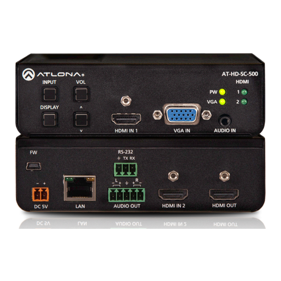
Panel Description AT-HD-SC-500 INPUT HDMI DISPLAY Front Rear HDMI IN 1 VGA IN AUDIO IN AT-HD-SC-500 RS-232 INPUT HDMI DISPLAY HDMI IN 1 VGA IN AUDIO IN HDMI OUT AUDIO OUT HDMI IN 2 DC 5V RS-232 9 11 INPUT 11 HDMI 2 AUDIO OUT HDMI IN 2... -
Page 11: Installation
Installation RS-232 The AT-HD-SC-500 provides RS-232 control between an automation system and an RS-232 device. This step is optional. 1. Use wire strippers to remove a portion of the cable jacket. 2. Remove at least 3/16” (5 mm) from the insulation of the RX, TX, and GND wires. 3. -
Page 12: Audio
Installation Audio The AUDIO OUT connector on the AT-HD-SC-500 provides the connection of either balanced or unbalanced audio outputs using XLR connectors. Use the included 5-pin Phoenix terminal block. Balanced audio connections use two signal wires and a ground to minimize interference in audio signals. Unbalanced audio connections use one signal wire and a ground and are used if system components don’t support balanced signals. -
Page 13: Connection Diagram
Installation Connection Diagram r ic R SY R S -2 ID G 3 .5 ST ER M IC LI N r ic R SY IN P AT-PA100-G2 Speakers Projector AT-HD-SC-500 C -5 D -S A T -H D IO A IN IN P P L A D IS... -
Page 14: Ip Configuration
Installation IP Configuration The AT-HD-SC-500 is shipped with DHCP enabled. Once connected to a network, the DHCP server (if available), will automatically assign an IP address to the unit. Use an IP scanner, along with the MAC address on the bottom of the unit, to identify both the unit and its IP address on the network. -
Page 15: Using The Web Gui
Installation • Setting DHCP mode 1. Connect to the AT-HD-SC-500 using RS-232 or Telnet. 2. At the command line, execute the IPDHCP command using the on argument, as shown. All characters are case-sensitive. IPDHCP on Once DHCP is enabled, the unit will be assigned an IP address by the DHCP server (if present). Using the Web GUI Network Page (page 44) in the web GUI, allows the AT-HD-SC-500 to use either DHCP or static IP mode. -
Page 16: Device Operation
Device Operation Selecting the Input Press the INPUT button to cycle through each of the available inputs on the unit. The unit will always retain the last selected input when the unit is powered-off. 1. Below, the HDMI 1 LED indicator is bright green, indicating that HDMI IN 1 is the active input. This is the default port selection of the AT-HD-SC-500. -
Page 17: Passing Analog Audio
Device Operation Passing Analog Audio The AT-HD-SC-500 can pass two-channel analog audio, by itself, or with a VGA signal. The signal is embedded on the HDMI output. 1. Connect a 3.5 mm mini-stereo cable from the AUDIO IN port to the analog audio source. 2. -
Page 18: Configuration And Management Interfaces
Configuration and Management Interfaces The On-Screen Display (OSD) The AT-HD-SC-500 includes a built-in OSD menu system to manage and control all video features. 1. Press and hold the DISPLAY button, until the OSD is shown. AT-HD-SC-500 INPUT HDMI Main Menu Input Select Input Resolution Output Resolution... -
Page 19: Input Select
Configuration and Management Interfaces Input Select Selects the desired input. This can also be done using the INPUT button on the front panel. Refer to Selecting the Input (page 16) for more information. 1. Under the Main Menu, highlight the Input Select menu item using the VOL UP/DN buttons on the front panel. 2. -
Page 20: Output Resolution
Configuration and Management Interfaces Output Resolution Selects the desired output resolution. The default output resolution is 720p (1280x720). The Output Resolution menu consists of three pages. 1. Under the Main Menu, highlight the Output Resolution menu item using the VOL UP/DN buttons on the front panel. -
Page 21: Aspect
Configuration and Management Interfaces Picture Adjust Brightness Contrast Saturation Sharpness Picture Reset ColorSpace Menu Back 8. Press the VOL UP/DN buttons to select the desired value. Press the VOL UP button to increase the value; press VOL DN to decrease the value. 9. -
Page 22: Overscan
Configuration and Management Interfaces Overscan Adjusts the overscan setting of the output video signal. By default, overscan is disabled. 1. Under the Main Menu, highlight the Overscan menu item using the VOL UP/DN buttons on the front panel. 2. Press the DISPLAY button. 3. - Page 23 Configuration and Management Interfaces Audio Audio On Off HDMI Audio Audio Treble [+15 Bass HDMI1 EBD. Aud Auto HDMI2 EBD. Aud Auto Menu Back Setting Description Audio On Off Provides muting of both HDMI and analog audio outputs. Set this value to Off to mute all audio.
-
Page 24: Osd
Configuration and Management Interfaces Adjusts the appearance and position of the On-Screen Display (OSD) on the screen. 1. Under the Main Menu, highlight the Audio menu item using the VOL UP/DN buttons on the front panel. 2. Press the DISPLAY button. 3. -
Page 25: Control Settings
Configuration and Management Interfaces 5. Press the DISPLAY button to confirm the selection. 6. The current value will be highlighted in green and surrounded by brackets and two arrowheads. 7. Press the VOL UP/DN buttons to change the value. For settings that contain a value, press the VOL UP button to increase the value;... - Page 26 Configuration and Management Interfaces * Consumer Electronics Control (CEC): Atlona has confirmed proper CEC functionality with several current models of Samsung, Panasonic, and Sony displays. However, it is not guaranteed that CEC will work with all displays. Many manufacturers do not support the CEC “off” command, and older displays use proprietary commands. Atlona only supports displays that use the CEC command structure defined in HDMI 1.2a.
-
Page 27: Others
Configuration and Management Interfaces 5. Press the DISPLAY button to confirm the selection. 6. The current value will be highlighted in green and surrounded by brackets and two arrowheads. 7. Press the VOL UP/DN buttons to change the value. 8. Press the DISPLAY button to confirm the change. 9. - Page 28 Configuration and Management Interfaces Setting Description HDMI2 HDCP Provides control over the transmission of HDCP content for HDMI 2. Refer to note, on the previous page. The following options are available: • Compliant - Forces detection of HDCP-compliant sink devices. If the sink device is not HDCP-compliant, then no content will be transmitted.
-
Page 29: Information
Configuration and Management Interfaces Information The Information displays current information about the AT-HD-SC-500. None of the fields within the Information menu can be edited. 1. Under the Main Menu, highlight the Information menu item using the VOL UP/DN buttons on the front panel. 2. -
Page 30: The Web Gui
Configuration and Management Interfaces The Web GUI The AT-HD-SC-500 includes a built-in web GUI. Atlona recommends that the web GUI be used to control the AT-HD-SC-500, as it provides intuitive management of all features. The AT-HD-SC-500 is shipped with DHCP enabled. Once connected to a network, the DHCP server will automatically assign an IP address to the unit. - Page 31 Configuration and Management Interfaces 7. The Info page will be displayed. Menus The dark-colored bar, near the top of the screen, is the menu bar. When the mouse is moved over each menu element, it will be highlighted in light orange. Once the desired menu element is highlighted, click the left mouse button to access the settings within the menu.
- Page 32 Configuration and Management Interfaces Toggles Several settings within the Web GUI use toggles, which enable, disable, or assign one of two settings. In most cases, when the toggle is blue, this means the feature is enabled. In addition, the toggle will be set to the ON or ENABLED position.
- Page 33 Configuration and Management Interfaces Buttons Buttons are used to execute an action or setting. Several pages within the Web GUI include a Save button. Clicking the Save button will apply and save all settings in the current page. Other buttons, such as the Power command for CEC (found under the Display page), will send the power-on or power-off command to the display.
-
Page 34: Video Page
Configuration and Management Interfaces Video Page Input Input Selection Click this drop-down list to select the desired input. VGA Adjust In most situations, adjustment of the VGA signal should not necessary. However, if the VGA signal does not appear correctly, click the Adjust button to automatically correct the clock and phase. Auto Switch Three controls are available under the Auto Switch feature. - Page 35 Configuration and Management Interfaces Output Output Resolution Click the Output Resolution drop-down list and select the desired resolution. The default resolution is 720p. Output Resolutions 800x600p60 1600x1200p60 1280x720p59 1920x1080p25 1024x768p60 1680x1050p60 1280x720p60 1920x1080p29 1280x800p60 1920x1200pRB 1920x1080i50 1920x1080p30 1280x1024p60 1280x720p25 1920x1080i59 1920x1080p50 1366x768p60 1280x720p29...
-
Page 36: Audio Page
Configuration and Management Interfaces Audio Page HDMI Audio Click the drop-down list for HDMI 1 and HDMI 2 to select the input audio source used by each HDMI input. Setting Description Auto Automatically detects the audio source. If an HDMI cable with embedded audio is connected, the system will use the digital audio on the HDMI cable. -
Page 37: Picture Page
Configuration and Management Interfaces Picture Page Brightness Adjusts the brightness setting of the output signal. Range: 0 - 128 Contrast Adjusts the contrast setting of the output signal. Contrast is the difference between the lightest and darkest area of an image. Range: 0 - 128 Saturation Adjusts the color saturation of the output signal. -
Page 38: Edid Page
Configuration and Management Interfaces EDID Page HDMI Perfer Timing Sets the preferred timing for the HDMI input. VGA Prefer Timing Sets the preferred timing for the VGA input. HDMI1 HDCP Provides control over the transmission of HDCP content for HDMI 1. The following options are available: •... -
Page 39: Display Page
Configuration and Management Interfaces Display Page CEC Command Click the ON button to send the power-on command to the display device. Click the OFF button to toggle the power state to off. System Settings Display Auto Power On Set this toggle to ENABLED to allow the AT-HD-SC-500 to send the power-on command to the display when an A/V signal is detected. - Page 40 Configuration and Management Interfaces Display Warm Up Timer Sets the projector lamp warm-up timer, in seconds. During the warm-up interval, the AT-HD-SC-500 will not start the auto power-off timer. This value specifies the time interval that must elapse, after the display control “on” command is sent, before the display “power off”...
- Page 41 Configuration and Management Interfaces RS-232 Page Baud rate Sets the baud rate for the AT-HD-SC-500. The following options are available: 2400, 4800, 9600, 19200, 28800, 57600, 115200. Data bit Sets the number of data bits used to represent each character of data. The following options are available: 5, 6, 7, 8, 9.
-
Page 42: Osd Page
Configuration and Management Interfaces OSD Page Position Sets the position of the OSD on the display. The following options are available. Left Top, Right Top, Right Bottom, Left Bottom, Center. Transparency Adjusts the transparency setting of the OSD. Range: 5 to 100. Info Timer The duration, in seconds, of how long the Display Info screen is displayed. -
Page 43: Config Page
Configuration and Management Interfaces Config Page Old Username This field cannot be changed. “root” is the administrator user. Old Password Enter the current password for the “root” username in this field. The default password is “Atlona”. New Username This field cannot be changed. Save Click this button to save all changes. -
Page 44: Network Page
Configuration and Management Interfaces Network Page IP Mode Click this toggle to set the IP mode of the AT-HD-SC-500. By default, the AT-HD-SC-500 is set to DHCP mode. Enter the IP address of the AT-HD-SC-500 in this field. This field will only be available if IP Mode is set to STATIC IP. Netmask Enter the subnet mask in this field. - Page 45 Configuration and Management Interfaces Factory Default Sets the AT-HD-SC-500 to factory-default settings. Choose File Click this button to select the firmware file, when upgrading the firmware on the AT-HD-SC-500. Save Click this button to save all changes to the network settings. Update Click this button to begin the upgrade procedure.
-
Page 46: Solution Setup And Configuration Guide
Solution Setup and Configuration Guide The following sections provide step-by-step instructions for the following topics: • Input Auto-Switching • Display Control Input Auto Switching The AT-HD-SC-500 provides auto-switching capability, which will automatically switch the input to the most recently- connected or powered source when a source is disconnected. For example, if the connection sequence is HDMI 2 > HDMI 1 >... - Page 47 Solution Setup and Configuration Guide 4. Press and release the DISPLAY button. The Others menu will be displayed. Others In Auto Switch Off VGA Auto Adj. HDMI1 HDCP Compliant HDMI2 HDCP Compliant Mirror-V ASP Background Grey Menu Back 5. Press the VOL UP/DN buttons to select the In Auto Switch option. 6.
-
Page 48: Using The Web Gui
Solution Setup and Configuration Guide Using the Web GUI Refer to The Web GUI (page 30) for more information if necessary. 1. Launch a web browser. 2. In the address bar, type the IP address of the AT-HD-SC-500. 3. Enter the login credentials and click the Submit button. The default credentials are listed below: Username: root Password:... - Page 49 Solution Setup and Configuration Guide 6. Click the Auto Switch mode toggle button to enable (ON) or disable (OFF) auto-switching. 7. Click the Fallback Port drop-down list to select the desired mode of operation. Fallback Port Description HDMI 1 Automatically switches to HDMI 1. HDMI 2 Automatically switches to HDMI 2.
-
Page 50: Display Control
Solution Setup and Configuration Guide Display Control The AT-HD-SC-500 provides both a LAN and RS-232 port, which allows commands to be sent from the AT-HD- SC-500 to a connected display over a serial cable or over Ethernet. No external control system is required. The DISPLAY and VOL (up/down) buttons can be programmed to toggle power on the display and/or adjust the output volume of the display (if the display has speakers). - Page 51 Solution Setup and Configuration Guide 7. Set the RS-232 settings for the display (sink) device. These settings must match the device settings for the display. Otherwise, RS-232 control will not function. Refer to the User Manual of the display device for information.
- Page 52 Solution Setup and Configuration Guide HEX Command Strings a. Enter the hexadecimal command string is the correct field. An example power-on command for a display might be: \xBE\xEF\x03\x06\x00\xBA\xD2\x01\x00\x00\x60\x01\x00\x0D This command would be entered in the ON field. Consult the documentation for the display for the correct command strings.
-
Page 53: Using Ip
Solution Setup and Configuration Guide Using IP Instead of using a serial cable to send commands, this method uses an Ethernet cable to send commands from the AT-HD-SC-500 to the display device. AT-HD-SC-500 INPUT HDMI 1. Connect an Ethernet cable from the LAN port on the AT-HD-SC-500, to the LAN port on the display. DISPLAY to display HDMI IN 1... - Page 54 Solution Setup and Configuration Guide 7. Under System Settings, click the Control Type drop-down list and select IP. 8. Locate the TCP/IP Settings of Controlled Device section and enter the following information: a. IP Mode If the device does not require a login, then set this drop-down value to Non-Login. If the device requires login credentials, select Login from the drop-down list.
-
Page 55: Appendix
Appendix Updating the Firmware Updating the firmware can be completed using either the USB interface or the web GUI. Atlona recommends using the web GUI for updating the firmware. However, If a network connection is not available, the AT-HD-SC-500 firmware can be updated using a USB-A to USB mini-B cable. Using the Web GUI Requirements •... -
Page 56: Using Usb
Appendix 7. Click the OK button to begin the firmware update process. Click the Cancel button to cancel the process. 8. The update process will take approximately 60 seconds and will automatically reboot the AT-HD-SC-500. 9. After the firmware update process is complete, the Login screen will be displayed. Using USB Requirements •... - Page 57 Appendix 4. The USB UPDATE folder will be displayed. If this folder is not displayed, automatically, select the USB UPDATE drive from Windows Explorer. 7. Delete all files from the USB UPDATE drive, if any are present. 8. Drag-and-drop the HDSC-500-FW-[version].BIN firmware file to the drive. 9.
-
Page 58: Mounting Instructions
Appendix Mounting Instructions The AT-HD-SC-500 includes two mounting brackets, which can be used to attach the unit to any flat surface. Use the enclosure screws, on the sides of the unit to attach the mounting brackets. 1. Using a small Phillips screwdriver, remove the four screws from the left side of the enclosure. -
Page 59: Default Settings
Appendix Default Settings The following tables list the factory-default settings for the AT-HD-SC-500. Feature Settings Video Input Selection HDMI 1 Auto Switch mode Fallback Port Previous Fallback Time (Sec) Output Resolution 1280x720p60 Color Space Aspect Full Overscan Mirror-V ASP Background Grey Audio HDMI 1... - Page 60 Appendix Feature Settings System IP Mode DHCP Static IP Address (default) 192.168.1.254 Netmask 255.255.255.0 Gateway 192.168.1.1 Telnet Port Telnet Login Mode Telnet Timeout 120 (seconds) Broadcast RS-232 Baud Rate 115200 Data Bit Parity None Stop bit Position Left-Top Transparency Info. Timer Menu Timer Info.
-
Page 61: Specifications
Appendix Specifications Video HD/SD Resolutions (input) 1080p@23.98/24/25/29.97/30/50/59.94/60Hz, 1080i@50/59.94/60Hz, 720p@50/59.94/60Hz, 576p, 576i, 480p, 480i, 1920×1200, 1680×1050, 1600×1200, 1600×900, 1440×900, 1400×1050, 1366×768, 1360×768, 1280×1024, 1280×800, 1280×768, 1152×864, 1024×768, 800×600, 640×480 HD/SD Resolutions (output) 1080p@23.98/24/25/29.97/30/50/59.94/60Hz, 1080i@50/59.94/60, 720p@25/29.97/30/50/59.94/60, 1920×1200, 1680×1050, 1600×1200, 1600×900, 1400×1050, 1366×768, 1280×1024, 1280×800, 1024×768, 800×600 Color Space YUV, RGB... -
Page 62: Index
Index RS-232 baud rate Analog audio HDCP data bits passing settings parity bit Aspect ratio 21, 35 20, 37 stop bit Audio embedding muting passing analog audio Information Safety information settings displaying Saturation 20, 37 Auto-switching Input Sharpness using the OSD selecting 16, 19 Specifications... - Page 63 Toll free US International atlona.com 877.536.3976 41.43.508.4321 • • © 2019 Atlona Inc. All rights reserved. “Atlona” and the Atlona logo are registered trademarks of Atlona Inc. All other brand names and trademarks or registered trademarks are the property of their respective owners. Pricing, specifications and availability subject to change without notice.
Need help?
Do you have a question about the Atlona AT-HD-SC-500 and is the answer not in the manual?
Questions and answers