Advertisement
INSTALLATION AND MAINTENANCE INSTRUCTIONS
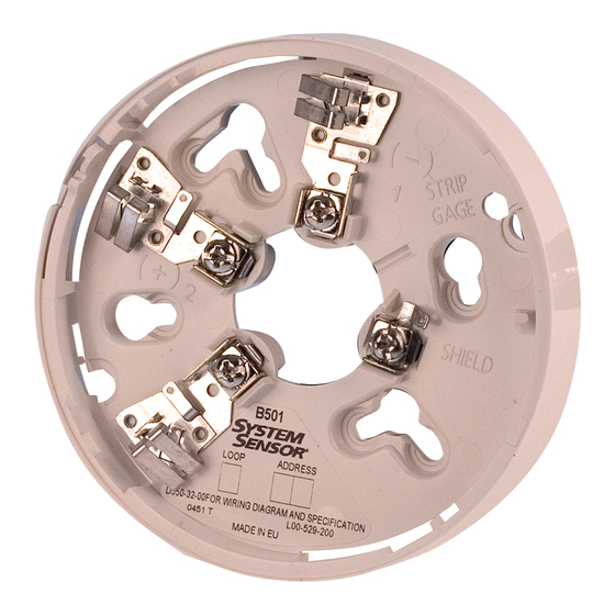
B501 Plug-in Detector Base
SPECIfICATIONS
Diameter:
Mounting:
Electrical Ratings – includes base and detector
Voltage Range:
Standby Current (Nominal):
Power-Up Surge at Max. Rated Voltage: 1.5mA–Sec.
LED Current (Nominal):
Operating Temperature Range:
BEfORE INSTALLINg
Please thoroughly read the System Sensor manual, System Smoke Detectors
Application Guide, which provides detailed information on detector spacing,
placement, zoning, wiring, and special applications. Copies of this manual are
available at no charge from System Sensor.
gENERAL DESCRIPTION
The B501 is a plug in detector base intended for use in an intelligent system with
screw terminals provided for power (+) and (–), and remote annunciator con-
nections. The communication takes place over the power (+) and (–) lines.
BASE TERMINALS
No.
Function
1
Power (–), Remote Annunciator (–)
2
Power (+)
3
Remote Annunciator (+)
fIgURE 1. TERMINAL LAyOUT:
BASE
TERMINALS
3
WIRINg INSTALLATION gUIDELINES (SEE fIgURE 2)
All wiring must be installed in compliance with the National Electrical Code
and the local authority having jurisdiction. Proper wire gauges should be
used. The conductors used to connect the smoke detectors to control pan-
els and accessory devices should be color-coded to prevent wiring mistakes.
Improper connections can prevent a system form responding properly in the
event of a fire.
D550-02-00
4.0 inches (10.2cm)
50mm, 60mm, and 70mm centers
15 to 32 VDC
150µA at 24 VDC
6mA at 24 VDC
Refer to applicable sensor Operating Temperature Range
TAMPER PROOF
TAB
2(+)
1(–)
C0131-00
firealarmresources.com
For signal wiring (the wiring between interconnected detectors and modules),
it is recommended that the wiring be no smaller than 18 gauge (1.0 square
mm). Wire sizes up to 12 gauge wire (2.5 square mm) may be used with the
base. For best system performance, the power (+) and (–) loop wires should
be twisted pair or shielded cable installed in separate grounded conduit to
protect the loop from extraneous electrical interference. If a cable shield is pro-
vided, the shield connection to and from the base must be continuous by us-
ing wire nuts, crimping, or soldering as appropriate for a reliable connection.
Wire Connections are made by simply stripping about
tion from the end of the wire (use strip gauge molded in base), sliding the
bare end of the wire under the clamping plate and tightening the clamping
plate screw. Do not loop the wire under the clamping plate.
The zone wiring of the detector base should be checked before the detector
heads are installed in them. The wiring should be checked for continuity, po-
larity in the base, and dielectric tests.
The base contains a label to write the zone, address, and type of detector to
be installed at that location. This information is used to set the address of the
detector head that will later be plugged into the base and to verify the type
required for that location.
fIgURE 2. TyPICAL WIRINg DIAgRAM fOR 2-WIRE LOOP:
REMOTE
ANNUNCIATOR
+
-
(+)
2
3
1
(–)
(–)
CLASS A OPTIONAL WIRING
(+)
TAMPERPROOf fEATURE
NOTE: Do Not use the tamper-resistant capability if the XR2 or XR2B Removal
Tool will be used. This detector base also includes an optional tamperproof
feature that when activated prevents removal of the detector without the use
of a tool.
To activate this feature, simply break off the tab on the detector base shown in
Figure 3A, and install the detector. To remove the detector from the base once
the tamperproof feature has been activated, place a small-bladed screwdriver
into the small hole on the side of the base and push the plastic lever away
from the detector head (see Figure 3B). This will allow the detector to be ro-
tated counterclockwise for removal.
The tamperproof feature may be defeated by breaking and removing the plas-
tic lever from the base, however this prevents ever using the feature again.
1
3825 Ohio Avenue, St. Charles, Illinois 60174
1-800-SENSOR2, FAX: 630-377-6495
www.systemsensor.com
3
⁄
of an inch of insula-
8
CAUTION: DO NOT LOOP WIRE
UNDER TERMINAL 1 OR 2.
BREAK WIRE RUN TO PROVIDE
SUPERVISION OF CONNECTIONS.
2
2
3
3
1
I56-0357-007R
1
C0133-00
Advertisement
Table of Contents

Related Manuals for System Sensor B501


Summary of Contents for System Sensor B501
- Page 1 If a cable shield is pro- The B501 is a plug in detector base intended for use in an intelligent system with vided, the shield connection to and from the base must be continuous by us- screw terminals provided for power (+) and (–), and remote annunciator con-...
- Page 2 Repair Department, RA #__________, 3825 Ohio Avenue, St. Charles, IL 60174. Please System Sensor warrants its enclosed smoke detector base to be free from defects in ma- include a note describing the malfunction and suspected cause of failure. The Company...
Need help?
Do you have a question about the B501 and is the answer not in the manual?
Questions and answers