Table of Contents
Advertisement
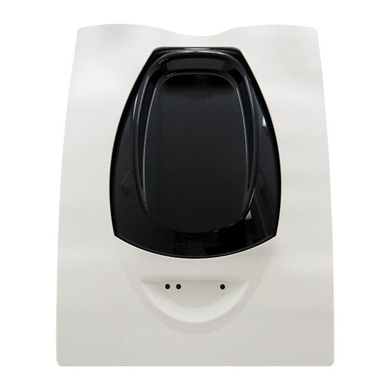
INSTALLATION AND MAINTENANCE INSTRUCTIONS
BEAM1224, BEAM1224S
Single-ended Reflected Type
Projected Beam Smoke Detector
SPECIfICATIONS
GENERAL
Range:
Sensitivity:
Spacing:
Response Time:
Trouble Conditions:
Test/Reset Features:
Indicators:
ENVIRONMENTAL
Temperature:
Humidity:
MECHANICAL
Shipping Weight:
Shipping Size:
Mounting:
Wiring:
Adjustment Angle:
Paintable Trim Ring:
ELECTRICAL
Voltage:
Maximum Ripple Voltage:
Current (24 VDC):
Current (Test Mode, BEAM1224S only):
Relay Contacts:
Reset Time:
Start-up Time (after 2 min. reset):
Alarm Verification Time:
Remote Output (Alarm & Trouble):
BEfORE INSTALLINg
Please thoroughly read this manual and applicable sections of System Sensor's
Projected Beam Detector Application Guide. Copies of this manual are avail-
able from System Sensor.
gENERAL DESCRIPTION
System Sensor Model BEAM1224/BEAM1224S is a long range projected beam
smoke detector designed to provide open area protection. It is to be used
D400-73-00
16 to 230 Feet (5 to 70m); 230 to 328 Feet (70 to 100m) using optional accessory BEAMLRK
25% to 50% Total Obscuration in 6 levels
Level 1 = 25%
Level 2 = 30%
Level 3 = 40%
Level 4 = 50%
Level 5 = 30% to 50% (Acclimate)
Level 6 = 40% to 50% (Acclimate)
30 to 60 Feet (9.1 to 18.3m)
ALARM - 20 seconds typical; TROUBLE - 30 seconds typical
Beam Blockage (96% or More Obscuration)
Improper Initial Alignment
Self-compensation limit reached (service needed)
In Alignment mode
Integral Sensitivity Test Filter (BEAM1224S only)
Sensitivity Filter (Incremental scale on reflector)
Local Alarm Test Switch
Local Alarm Reset Switch
Remote Test and Reset Switch Capability
ALARM - Remote Output, Local LED (red)
TROUBLE - Remote Output, Local LED (yellow), Blink Pattern Indicates Trouble Diagnostics
NORMAL OPERATION - Local LED (flashing green once every 5 sec.)
ALIGNMENT AIDS - Optical Gunsight (coarse adjustment), 00 to 99 Digital Display (fine adjustment)
RELAYS - Alarm; Trouble
SENSITIVITY - Digital Display Readout in Percent Obscuration
–22°F to 131°F (–30°C to 55°C); NOTE: For applications below 32°F (0°C), see Special Applications on page 2
10% to 93% RH Non-condensing
Complete unit: 3.9 lbs. (1.77 kg)
15˝×10.5˝×6.5˝ (381mm × 267mm × 165mm)
Wall only without optional accessories
Plug-in Terminal Blocks (12 to 22AWG)
±10° Horizontal and Vertical
May be painted using enamel or acrylic type paints
10.2 to 32 VDC (BEAM1224); 15 to 32 VDC (BEAM1224S)
6.0 volts (Peak-to-peak); NOTE: ripple must not fall below minimum operating voltage specification
Avg. Standby -
17mA Max.
Avg. Alarm -
38.5mA Max.
Avg. Trouble -
8.5mA Max.
Avg. Alignment -
28mA Max.
Peak Test-
500mA Max.
0.5A at 30 VDC
0.3 Seconds Max.
60 sec. Max.
5 sec. Max.
VOLTAGE - 15 to 32 VDC; NOTE: Output voltage same as device input voltage
CURRENT - 15mA maximum; 6mA minimum; NOTE: Output current is limited by 2.2Kohm resistor
with UL-listed, separately supplied power (4-wire) control panels only. The
detector consists of a transmitter/receiver unit and a reflector. Smoke entering
the area between the transmitter/receiver and reflector causes a reduction in
signal. When the obscuration reaches alarm thresholds (chosen at the trans-
mitter/receiver unit), the detector generates an alarm signal. Complete block-
age of the beam causes a trouble signal. Slow changes in obscuration due to
a build up of dirt or dust on the lens of the detector are compensated for by
1
3825 Ohio Avenue, St. Charles, Illinois 60174
800/736-7672, FAX: 630/377-6495
www.systemsensor.com
I56-2294-005R
Advertisement
Table of Contents

Related Manuals for System Sensor BEAM1224


Summary of Contents for System Sensor BEAM1224
- Page 1 May be painted using enamel or acrylic type paints ELECTRICAL Voltage: 10.2 to 32 VDC (BEAM1224); 15 to 32 VDC (BEAM1224S) Maximum Ripple Voltage: 6.0 volts (Peak-to-peak); NOTE: ripple must not fall below minimum operating voltage specification Current (24 VDC): Avg.
- Page 2 BEAMSMK diagnosing the cause of a trouble signal. It will also blink the amount of drift The BEAMSMK allows System Sensor reflected beam detectors to be mounted compensation that has been used at the conclusion of the test. Trouble signals when surface wiring is used.
-
Page 3: Detector Placement
Authority Having Jurisdiction (AHJ). For general tions such as joists, ducts, etc. See Figure 1 In addition, beam smoke detectors information on the placement of detectors, read System Sensor’s Projected should be mounted vertically at least 10 feet (3.0 m) from the floor to avoid Beam Detector Application Guide. - Page 4 MOUNTINg INSTRUCTIONS the light beam from the transmitter to the receiver. If this occurs, the detector The transmitter/receiver unit may be mounted over a recessed junction box. will not be able to distinguish these reflections from those of the reflector and The cavity behind the detector is then used for routing of the wiring from the the protected space will be compromised.
- Page 5 C0319-01 INSTALLATION/ALIgNMENT Reference Figures 10 through 14 for installation, alignment, and maintenance. The alignment of the BEAM1224/BEAM1224S is divided into four steps: coarse alignment, fine adjustment, final gain adjustment, and final verification. It is C0271-00 necessary for all four steps to be executed properly to ensure proper alignment WARNING: Disable the zone or system before applying power to the beam of the product.
-
Page 6: Pre-Alignment Checklist
fIgURE 10. SwITCh LOCATIONS: fIgURE 11. ALIgNMENT ADjUSTMENT LOCATIONS: ALIGNMENT MIRROR ALIGNMENT POSITION ALIGNMENT GUNSIGHT INDICATOR DIGITAL SIGNAL STRENGTH READOUT ALIGNMENT SENSITIVITY TEST HORIZONTAL ADJUSTMENT OPTICS LOCK-DOWN SCREWS RESET VERTICAL ADJUSTMENT C0264-00 C0274-00 fIgURE 12. COARSE ALIgNMENT PROCEDURE: PRE-ALIgNMENT ChECkLIST •... - Page 7 one at a time going back and forth between them until a peak value is STEP 4. fINAL vERIfICATION indicated. If a value of 90 is achieved, the detector will re-adjust the elec- This step is required to ensure the detector has been setup correctly and will tronic gain once again.
-
Page 8: Maintenance
Note: For the BEAM1224 this test does not satisfy the requirements of NFPA72 Place the blocking material over the reflector, lining it up with the gradu- for periodic maintenance and sensitivity verification of beam type detectors. -
Page 9: Appendix I. Operation Modes And Troubleshooting Guide
RTS151/KEY or time-out Fail Result time-out Local Test Per fault RTS451/KEY or If local test fails will already Blink Open Open (BEAM1224) mode RTS151/KEY be in fault Fail Result Local Test Blinking the RTS451/KEY or amount of Close Close (BEAM1224) -
Page 10: Appendix Ii. Detector Drilling Template
APPENDIx II. DETECTOR DRILLINg TEMPLATE: 6.190˝ (157 mm) 4.345˝ (110 mm) Scale = 1:1 D400-73-00 I56-2294-005R... - Page 11 D400-73-00 I56-2294-005R...
-
Page 12: Appendix Iii. Reflector Drilling Template
APPENDIx III. REfLECTOR DRILLINg TEMPLATE: 5.512˝ (140mm) 8.465˝ (215mm) Scale = 1:1 D400-73-00 I56-2294-005R... -
Page 13: Fcc Statement
– Consult the dealer or an experienced radio/TV technician for help. ThREE-yEAR LIMITED wARRANTy System Sensor warrants its enclosed smoke detector to be free from defects in materials Department, RA #__________, 3825 Ohio Avenue, St. Charles, IL 60174. Please include a and workmanship under normal use and service for a period of three years from date note describing the malfunction and suspected cause of failure.
Need help?
Do you have a question about the BEAM1224 and is the answer not in the manual?
Questions and answers