Advertisement
INSTALLATION AND MAINTENANCE INSTRUCTIONS
B501 Plug-in Detector Base
Specifications
Diameter:
Mounting:
Electrical Ratings – includes base and detector
Voltage Range:
Standby Current (nominal):
Power-Up Surge at
Maximum Rated Voltage:
LED Current (nominal):
Operating Temperature Range:
Before Installing
Please thoroughly read the System Sensor manual, System
Smoke Detectors Application Guide, which provides detailed
information on detector spacing, placement, zoning, wiring,
and special applications. Copies of this manual are available
at no charge from System Sensor.
General Description
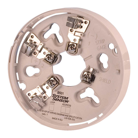
The B501 is a plug in detector base intended for use in an
intelligent system with screw terminals provided for power
(+) and (–), and remote annunciator connections. The
communication takes place over the power (+) and (–)
lines.
Base Terminals
No.
Function
1
Power (–), Remote Annunciator (–)
2
Power (+)
3
Remote Annunciator (+)
D550-02-00
4.0 inches (10.2cm)
50mm, 60mm, and 70mm centers
15-32 VDC
150µA at 24 VDC
1.5mA–Sec.
6mA at 24 VDC
32° to 150°F (0° to 66°C)
1
Figure 1. Terminal layout:
BASE
TERMINALS
3825 Ohio Avenue
St. Charles, Illinois 60174
1-800-SENSOR2, FAX: 630-377-6495
TAMPER PROOF
TAB
2(+)
1(–)
3
C0131-00
I56-357-06R
Advertisement
Table of Contents

Summary of Contents for System Sensor B501
- Page 1 Copies of this manual are available at no charge from System Sensor. General Description BASE The B501 is a plug in detector base intended for use in an TERMINALS intelligent system with screw terminals provided for power 2(+) (+) and (–), and remote annunciator connections.
- Page 2 Figure 2. Typical wiring diagram for 2-wire loop: REMOTE ANNUNCIATOR CAUTION: Do not loop wire under terminal 1 or 2. Break wire run to provide supervision of connections. CLASS A OPTIONAL WIRING C0133-00 Wiring Installation Guidelines (See Figure 2) All wiring must be installed in compliance with the Wire Connections are made by simply stripping about ⁄...
- Page 3 Figure 3A. Activating tamperproof feature: Figure 3B. Removing detector head from base: SCREWDRIVER TO PRESS PLASTIC LEVER BREAK TAB AT IN DIRECTION OF DOTTED LINE BY PLASTIC LEVER TWISTING TOWARD ARROW CENTER OF BASE. C0132-00 Tamperproof Feature Figure 4. Connection to remote annunciator terminal: NOTE: Do Not use the tamper-resistant capability if the XR2 or XR2B Removal Tool will be used.
- Page 4 Please refer to insert for the Limitations of Fire Alarm Systems Three-Year Limited Warranty System Sensor warrants its enclosed smoke detector base to be free from Sensor, Repair Department, RA #__________, 3825 Ohio Avenue, St. defects in materials and workmanship under normal use and service for a Charles, IL 60174.


Need help?
Do you have a question about the B501 and is the answer not in the manual?
Questions and answers