Table of Contents
Advertisement
Quick Links
INSTALLATION AND MAINTENANCE INSTRUCTIONS
BEAM200, BEAM200S
Single-ended Reflected Type
Projected Beam Smoke Detector
SPECIfICATIONS
GENERAL
Range:
Sensitivity:
Spacing:
Response Time:
Trouble Conditions:
Test/Reset Features:
Indicators:
Style 7 Operation:
ENVIRONMENTAL
Temperature:
Humidity:
MECHANICAL
Shipping Weight:
Shipping Size:
Mounting:
Wiring:
Adjustment Angle:
Paintable Trim Ring:
ELECTRICAL
Voltage:
Standby Current:
External Supply (BEAM200S only): VOLTAGE - 15 to 32 VDC
Remote Output (alarm):
BEfORE INSTALLINg
Please thoroughly read this manual and applicable sections of System Sensor's
Projected Beam Detector Application Guide. Copies of this manual are avail-
able from System Sensor.
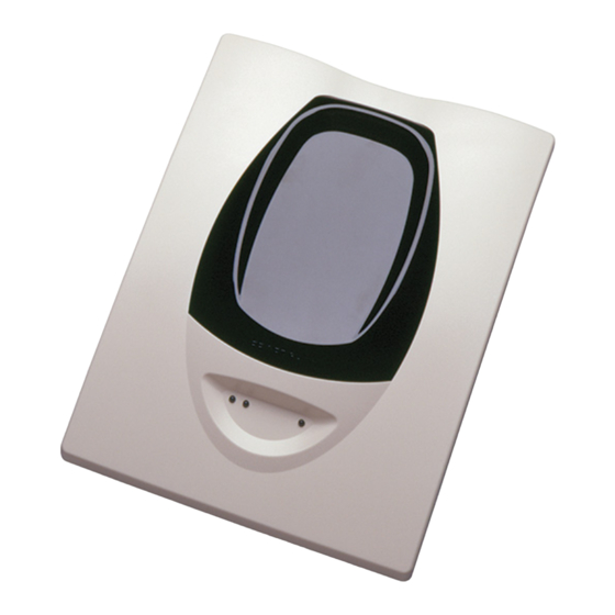
gENERAL DESCRIPTION
System Sensor Model BEAM200/BEAM200S is a long range projected beam
smoke detector designed to provide open area protection. It is to be used with
UL-listed compatible control panels only. The detector consists of a transmit-
ter/receiver unit and a reflector. When the obscuration reaches alarm thresh-
olds (chosen at the transmitter/receiver unit), the detector generates an alarm
signal. Complete blockage of the beam causes a trouble signal. Slow changes
in obscuration due to a build up of dirt or dust on the lens of the detector are
D400-74-00
16 to 230 Feet (5 to 70m); 230 to 328 Feet (70 to 100m) using optional accessory BEAMLRK
25% to 50% Total Obscuration in 6 levels
Level 1 = 25%
Level 2 = 30%
Level 3 = 40%
Level 4 = 50%
Level 5 = 30% to 50% (Acclimate)
Level 6 = 40% to 50% (Acclimate)
30 to 60 Feet (9.1 to 18.3m)
ALARM - 20 seconds typical; TROUBLE - 30 seconds typical
Beam Blockage (96% or More Obscuration)
Improper Initial Alignment
Self-compensation limit reached (service needed)
In Alignment mode
Integral Sensitivity Test Filter (BEAM200S only, requires additional external power supply)
Sensitivity Filter (Incremental scale on reflector)
Local Alarm Test Switch
Local Alarm Reset Switch
Remote Test and Reset Switch Capability
ALARM - Remote Output, Local LED (red)
TROUBLE - Remote Output, Local LED (yellow), Blink Pattern Indicates Trouble Diagnostics
NORMAL OPERATION - Local LED (flashing green with communication)
ALIGNMENT AIDS - Optical Gunsight (coarse adjustment), 00 to 99 Digital Display (fine adjustment)
SENSITIVITY - Digital Display Readout in Percent Obscuration
On-board isolators provide style 7 operation,(may be disabled via shunts on circuit board)
–22°F to 131°F (–30°C to 55°C) NOTE: for applications below 32°F (0°C) see Special Applications section of this manual.
10% to 93% RH Non-condensing
Complete unit: 3.9 lbs. (1.77 kg)
15˝ × 10.5˝ × 6.5˝ (381mm × 267mm × 165mm)
Wall only without optional accessories
Plug-in Terminal Blocks (12 to 22AWG)
±10° Horizontal and Vertical
May be painted using enamel or acrylic type paints
15 to 32 VDC
Avg. Standby -
2mA Max. (1 communication every 5 sec., LED flashing, SLC @ 24 V)
Max. Alarm (LED on) -
8.5mA Max.
Max. Trouble (LED on) -
4.5mA Max.
Max. Alignment -
20mA Max.
CURRENT - 0.5A Max.
VOLTAGE - 15 to 32 VDC, NOTE: Output voltage same as device input voltage.
CURRENT - 15mA maximum, 6mA minimum; NOTE: Output current is limited by 2.2Kohm resistor
compensated for by a microcontroller that continuously monitors the signal
strength and periodically updates the alarm and trouble thresholds. When the
self-compensation circuit reaches its limit, the detector generates a trouble
signal, indicating the need for service.
Three LEDs on the detector indicate the current status: a red LED for alarm, a
yellow LED for trouble, and a blinking green LED for standby operation. Note:
The panel controls the status of the red and green LEDs. The local reset but-
ton is accessible by removing the outer paintable trim ring. The yellow LED
will blink in specific patterns to provide a diagnostic aid when diagnosing the
cause of a trouble signal. It will also blink the amount of drift compensation
that has been used at the conclusion of the test. Trouble signals automati-
cally reset upon removing the cause of trouble. Red and yellow LEDs can be
1
3825 Ohio Avenue, St. Charles, Illinois 60174
1.800.SENSOR2; Fax: 630.377.6495
www.systemsensor.com
I56-2289-005R
Advertisement
Table of Contents

Related Manuals for System Sensor BEAM200S


Summary of Contents for System Sensor BEAM200S
- Page 1 Improper Initial Alignment Self-compensation limit reached (service needed) In Alignment mode Test/Reset Features: Integral Sensitivity Test Filter (BEAM200S only, requires additional external power supply) Sensitivity Filter (Incremental scale on reflector) Local Alarm Test Switch Local Alarm Reset Switch Remote Test and Reset Switch Capability...
- Page 2 The following accessories can be purchased separately for use with this beam detector. BEAMLRK The BEAMLRK allows System Sensor reflected beam detectors to be installed at separations between 230 and 328 feet (70 to 100 meters). At these distances, four 8˝×8˝ reflectors must be used to provide enough reflected infrared light.
- Page 3 Some fire codes specify spacing on a given center-to-center distance between fIgURE 3. SLOPED CEILINg (ShED TyPE): detectors under ideal conditions. This spacing is based on rooms with smooth 3 F T . ceilings and no physical obstructions between the contents being protected ( 0 .
- Page 4 the base. All four hole locations should be used to provide a secure mounting. Light sources of extreme intensity such as sunlight and halogen lamps, if di- The outer housing of the beam detector is held to the base using four screws. rected at the receiver, can cause a dramatic signal change resulting in fault In order to mount the detector you must remove the outer housing first.
- Page 5 7. wIRINg DIAgRAM: Reference Figures 10 through 14 for installation, alignment, and maintenance. The alignment of the BEAM200/BEAM200S is divided into four steps: coarse alignment, fine adjustment, final gain adjustment, and final verification. It is necessary for all four steps to be executed properly to ensure proper alignment of the product.
-
Page 6: Step 1. Coarse Alignment
STEP 1. COARSE ALIgNMENT At this time it is possible to set the sensitivity of the detector using the sen- Refer to Figures 11 and 12 for this step. sitivity switch and digital display. See the Sensitivity Selection section of this manual for further details. - Page 7 fIgURE 10. SwITCh LOCATIONS: fIgURE 12. COARSE ALIgNMENT PROCEDURE: ALIGNMENT SENSITIVITY TEST REFLECTOR RESET C0265-00 fIgURE 13. hOUSINg SCREw LOCATIONS: SCREW LOCATIONS STYLE 7 ISOLATOR SHUNTS (SHOWN DISABLED) C0263-00 fIgURE 11. ALIgNMENT ADjUSTMENT LOCATIONS: ALIGNMENT MIRROR ALIGNMENT POSITION ALIGNMENT GUNSIGHT INDICATOR DIGITAL SIGNAL STRENGTH...
- Page 8 NOTE: Before testing the detector, check for the presence of the flashing green NOTE: For the BEAM200S the external power supply must be connected for the test switch to work. LED at the receiver, making sure not to disturb or block the beam. If it does not flash and the detector is not in trouble or alarm, power has been lost to B.
-
Page 9: Maintenance
4. Repeat the alignment procedure in this manual. If the alignment pro- cedure is successful repeat the test procedure. If the detector still fails the test it should be returned for repair. NOTE: For the BEAM200S, the external power supply must be con- nected for the test switch to work. MAINTENANCE... -
Page 10: Appendix I. Operation Modes And Troubleshooting Guide
APPENDIx I. OPERATION MODES AND TROUBLEShOOTINg gUIDE: Modes *Red Yellow and *Green Remote Dual Digital Display Initiating means Comments & Troubleshooting See Note Remote Trouble See Note Alarm Tips Below Output Below Output Normal Blink Blink Successful completion of initialization or detector reset Alignment Blink... -
Page 11: Appendix Ii. Detector Drilling Template
APPENDIx II. DETECTOR DRILLINg TEMPLATE 6.190˝ (157 mm) 4.345˝ (110 mm) Scale = 1:1 D400-74-00 I56-2289-005R... - Page 12 D400-74-00 I56-2289-005R...
-
Page 13: Appendix Iii. Reflector Drilling Template
APPENDIx III. REfLECTOR DRILLINg TEMPLATE 5.512˝ (140mm) 8.465˝ (215mm) Scale = 1:1 D400-74-00 I56-2289-005R... - Page 14 D400-74-00 I56-2289-005R...
-
Page 15: Fcc Statement
– Consult the dealer or an experienced radio/TV technician for help. ThREE-yEAR LIMITED wARRANTy System Sensor warrants its enclosed smoke detector to be free from defects in materials Department, RA #__________, 3825 Ohio Avenue, St. Charles, IL 60174. Please include a and workmanship under normal use and service for a period of three years from date note describing the malfunction and suspected cause of failure.
Need help?
Do you have a question about the BEAM200S and is the answer not in the manual?
Questions and answers