Table of Contents
Advertisement
Quick Links
INSTALLATION AND MAINTENANCE INSTRUCTIONS
B501BH
Sounder Base
Specifications
Base Diameter:
Base Height (less sensor):
Weight:
Operating Temperature Range:
Operating Humidity Range:
Electrical Ratings
External Supply Voltage:
Standby Current:
Alarm Current:
Maximum Ripple Voltage:
Start-up Capacitance:
Communication/Initiating Loop Supply
Current Draw from Remote Output
of Sensor to turn on Horn:
Sound Output:
Before Installing
Please read the System Smoke Detector Application Guide,
which provides detailed information on sensor spacing. place-
ment, zoning, wiring. and special applications. Copies of this
manual are available from System Sensor. NFPA 72 and NEMA
guidelines should be observed.
NOTICE: This manual should be left with the owner/user of
this equipment.
IMPORTANT: The detector used with this base must be tested
and maintained regularly following NFPA 72 requirements.
The detector should be cleaned at least once a year.
General Description
The B501BH sounder base is used with System Sensor 200 and
500 Series sensor heads. Refer to the appropriate manual for
more information on sensors.
The sounder base is intended for use with intelligent systems.
Refer to the panel manual for the maximum allowable num-
ber of units per loop. The sounder base requires an external
24VDC supply with reverse polarity capability or a relay mod-
ule configured to reverse the power as in Figure 5. The con-
nections for the external supply (terminals 1 and 2) and the
communication loop (terminals 3 and 4) are isolated to pre-
vent electrical interaction between them.
When the sensor's visible LEDs are latched on for approxi-
mately 10 seconds, the associated horn sounds. A loop of
horns can be made to sound by reversing the polarity of the
external supply when configured as in Figure 4 and 5. When
configured as in Figure 5, a loop of horns can also be made to
sound by turning on the Intelligent Relay Module.
D650-03-00
6.0 inches (15.2 cm)
2.3 inches (5.9 cm)
0.4 lb. (181 gm)
32° to 120°F (0° to 49°C)
10% to 93% Relative Humidity
17 to 32 VDC
1.0 mA maximum
15 mA maximum
10% of supply voltage
200 µF
700 µA maximum
Greater than 90 dBA measured in anechoic room at 10 feet, 24 volts. 85 dBA
minimum measured in UL reverberant room.
NOTE: When not used as a supplementary evacuation system
the external 24 VDC supply shall be treated as a component of
the main power supply system and shall fall under the require-
ments of the main power supply system per NFPA 72.
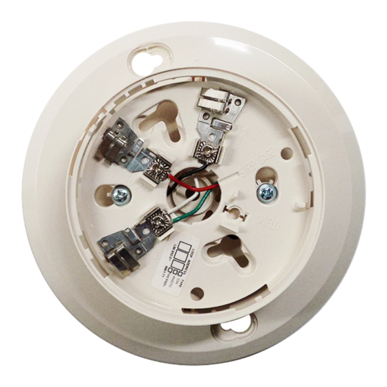
B501BH Terminals
No.
1
2
3
4
5
Terminals 3 and 4 are used for the communication circuit.
Mounting
Mount the B501BH directly to an electrical box, using the
mounting kit, supplied (see Figure 2).
The sounder base is 1.1-inches deep. Electrical boxes must be
4-inches square by at least 1
ommended.
NOTE: A maximum space of
the electrical box to the inside edge of the drywall or ceiling
tile is allowable.
Wiring Guidelines
All wiring must be installed in compliance with the National
Electrical Code and the local codes having jurisdiction and
must not be of such length or wire size which would cause
the base to operate outside of its published specifications. The
conductors used to connect smoke sensors to control panels
and accessory devices should be color coded to reduce the
likelihood of wiring errors. Improper connections can prevent
a system from responding properly in the event of a fire.
1
3825 Ohio Avenue, St. Charles, Illinois 60174
Function
External Supply Positive (+)
External Supply Negative (–)
Negative (–) Comm. Line In and Out
Positive (+) Comm. Line In and Out
Sounder Base Interconnect
1
⁄
2
1
⁄
1-800-SENSOR2, FAX: 630-377-6495
www.systemsensor.com
inches deep - 2
1
⁄
inches is rec-
8
inch from the outside edge of
8
I56-0491-007R
Advertisement
Table of Contents

Related Manuals for System Sensor Sounder Base B501BH


Summary of Contents for System Sensor Sounder Base B501BH
-
Page 1: Specifications
The detector should be cleaned at least once a year. General Description Terminals 3 and 4 are used for the communication circuit. The B501BH sounder base is used with System Sensor 200 and Mounting 500 Series sensor heads. Refer to the appropriate manual for Mount the B501BH directly to an electrical box, using the more information on sensors. - Page 2 For signal wiring (the wiring between interconnected sensors Figure 1. Terminal layout: or modules), it is recommended that the wire be no smaller than 18 gauge (1.0 square mm). Wire sizes up to 12 gauge (2.5 square mm) may be used with the base. For best system per- formance, the power (+ and –) wires and the communication circuit wires should be twisted pair or shielded cable installed in separate grounded conduit to protect the communication...
- Page 3 Figure 4. Wiring diagram: ing is accomplished by wiring the grouped devices together Detector Activates Sounder Base(s) - (Complies with UL268) using terminal 5, Sounder Base Interconnect, as shown in the diagram. UL has approved grouping for up to six B501BH bases with horn units.
- Page 4 Please refer to insert for the Limitations of Fire Alarm Systems THREE-YEAR LIMITED WARRANTY System Sensor warrants its enclosed smoke detector base to be free from defects in mate- Department, RA #__________, 3825 Ohio Avenue, St. Charles, IL 60174. Please include a rials and workmanship under normal use and service for a period of three years from date note describing the malfunction and suspected cause of failure.
Need help?
Do you have a question about the Sounder Base B501BH and is the answer not in the manual?
Questions and answers