Table of Contents
Advertisement
Quick Links
INSTALLATION AND MAINTENANCE INSTRUCTIONS
BEAM1224A, BEAM1224SA
Single-ended Reflected Type
Projected Beam Smoke Detector
SpECIfICATIONS
GENERAL
Range:
Sensitivity:
Spacing:
Response Time:
Trouble Conditions:
Test/Reset Features:
Indicators:
Environmental
Temperature:
Humidity:
Mechanical
Shipping Weight:
Shipping Size:
Mounting:
Wiring:
Adjustment Angle:
Paintable Trim Ring:
Electrical
Voltage:
Maximum Ripple Voltage:
Current (24 VDC):
Current (Test Mode)
Relay Contacts:
Reset Time:
Start-up Time (after 2 min. reset):
Alarm Verification Time:
Remote Output:
BEfORE INSTALLING
Please thoroughly read this manual and applicable sections of System Sensor's
Projected Beam Detector Application Guide. Copies of this manual are avail-
able from System Sensor.
D400-85-00
16 to 230 Feet (5 to 70m); 230 to 328 Feet (70 to 100m) using optional accessory BEAMLRK
25% to 50% Total Obscuration in 6 levels
Level 1 = 25%
Level 2 = 30%
Level 3 = 40%
Level 4 = 50%
Level 5 = 30% to 50% (Acclimate)
Level 6 = 40% to 50% (Acclimate)
30 to 60 Feet (9.1 to 18.3m)
ALARM - 20 seconds typical; TROUBLE - 30 seconds typical
Beam Blockage (96% or More Obscuration)
Improper Initial Alignment
Self-compensation limit reached (service needed)
In Alignment mode
Integral Sensitivity Test Filter (BEAM1224SA only)
Sensitivity Filter (Incremental scale on reflector)
Local Alarm Test Switch
Local Alarm Reset Switch
Remote Test and Reset Switch Capability
ALARM - Remote Output, Local LED (red)
TROUBLE - Remote Output, Local LED (yellow); Blink Pattern Indicates Trouble Diagnostics
NORMAL OPERATION - Local LED (flashing green once every 5 sec.)
ALIGNMENT AIDS - Optical Gunsight (coarse adjustment); 00 to 99 Digital Display (fine adjustment)
RELAYS - Alarm; Trouble
SENSITIVITY - Digital Display Readout in Percent Obscuration
–22°F to 131°F (–30°C to 55°C); NOTE: For applications below 32°F (0°C), see Special Applications section of this manual
10% to 93% RH Noncondensing
Complete unit: 3.9 lbs. (1.77 kg)
15" × 10.5" × 6.5" (381 mm × 267 mm × 165 mm)
Wall only without optional accessories
Plug-in Terminal Blocks (12 to 22AWG)
±10° Horizontal and Vertical
May be painted using enamel or acrylic type paints
10.2 to 32 VDC (BEAM1224A); 15 to 32 VDC (BEAM1224SA)
6.0 volts (Peak-to-peak); NOTE: ripple must not fall below minimum operating voltage specification
Avg. Standby:
17mA Max.
Avg. Alarm:
38.5mA Max.
Avg. Trouble:
8.5mA Max.
Avg. Alignment:
28mA Max.
(BEAM1224SA only); Peak Test - 500mA Max.
0.5A at 30 VDC
0.3 Seconds Max.
60 sec. Max.
5 sec. Max.
VOLTAGE - 15 to 32 VDC; NOTE: Output voltage same as device input voltage.
CURRENT - 15mA maximum; 6mA minimum; NOTE: Output current is limited by 2.2Kohm resistor
6581 Kitimat Rd. Unit 6 Mississauga, Ontario L5N 3T5
GENERAL DESCRIpTION
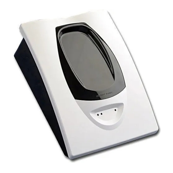
System Sensor Model BEAM1224A/BEAM1224SA is a long range projected
beam smoke detector designed to provide open area protection. It is to be used
with ULC-listed, separately supplied power (4-wire) control panels only. The
detector consists of a transmitter/receiver unit and a reflector. Smoke entering
the area between the transmitter/receiver and reflector causes a reduction in
1
1-800-SENSOR2, FAX: 905-812-0771
www.systemsensor.ca
I56-2541-005R
Advertisement
Table of Contents

Subscribe to Our Youtube Channel
Related Manuals for System Sensor BEAM1224SA


Summary of Contents for System Sensor BEAM1224SA
- Page 1 May be painted using enamel or acrylic type paints Electrical Voltage: 10.2 to 32 VDC (BEAM1224A); 15 to 32 VDC (BEAM1224SA) Maximum Ripple Voltage: 6.0 volts (Peak-to-peak); NOTE: ripple must not fall below minimum operating voltage specification Current (24 VDC): Avg.
- Page 2 BEAMSMK cause of a trouble signal. It will also blink the amount of drift compensation The BEAMSMK allows System Sensor reflected beam detectors to be mounted that has been used at the conclusion of the test. Trouble signals automati- when surface wiring is used. This kit must be used when mounting the trans- cally reset upon removing the cause of trouble.
-
Page 3: Mounting Locations
Alarm Code, as well as directives of the Authority Having Jurisdiction (AHJ). minimum of 12 inches (0.3m) from the ceiling or beneath structural obstruc- For general information on the placement of detectors, read System Sensor’s tions such as joists, ducts, etc. See Figure 1. In many cases, however, the Projected Beam Detector Application Guide. -
Page 4: Mounting Instructions
MOUNTING CONSIDERATIONS fOR SINGLE ENDED BEAM DETECTORS In cases where only one stable mounting surface as defined above can be used, the transmitter/receiver unit should be mounted to the stable surface There must be a permanent clear line of vision between the detector and the and the reflector should be mounted to the less stable surface. -
Page 5: Installation / Alignment
After a few moments the display will indicate a numeric value near 20. If the display reads “Lo” then the detector is not receiving The alignment of the BEAM1224A/BEAM1224SA is divided into four steps: enough light from the reflector. Go back and repeat the coarse alignment... -
Page 6: Step 4. Final Verification
fIGURE 10. SwITCh LOCATIONS NOTE: The alignment procedure is not complete yet. At this time it is possible to set the sensitivity of the detector using the sen- sitivity switch and digital display. See the Sensitivity Selection section of this manual for further details. - Page 7 fIGURE 7. wIRING DIAGRAM C0272-01 fIGURE 8. wIRING DIAGRAM (RTS451) fIGURE 9. wIRING DIAGRAM (RTS451) C0273-02 fIGURE 12. COARSE ALIGNMENT pROCEDURE C0319-00 C0265-00 D400-85-00 I56-2541-005R...
-
Page 8: Sensitivity Selection
Disable the zone or system undergoing maintenance to prevent unwanted alarms. Detectors must be tested after installation and following periodic maintenance. The sensitivity of the BEAM1224A/BEAM1224SA may be tested as follows: C0266-00 NOTE: Before testing the detector, check for the presence of the flashing SENSITIvITy SELECTION green LED at the receiver, making sure not to disturb or block the beam. -
Page 9: Maintenance Note
For the BEAM1224A this test does not satisfy the requirements of NFPA72 and/or ULC for periodic maintenance and sensitivity verification of beam type detectors. For the BEAM1224SA this test in conjunction with the complete reflector blockage test (see step 4 of the Installation/Alignment pro- cedure in this manual) does satisfy the requirements of NFPA72 and/or ULC for periodic maintenance and sensitivity verification of beam type detectors. -
Page 10: Appendix I. Operation Modes And Troubleshooting Guide
Close alignment exit complete after alignment Local Test Blinks out Blink RTS451/KEYA Close Close Detector remains in alarm (BEAM1224SA) the amount until reset or time-out Pass Result of drift used Local Test Per fault Blink RTS451/KEYA Open Open Detector remains in fault... -
Page 11: Appendix Ii. Detector Drilling Template
AppENDIx II. DETECTOR DRILLING TEMpLATE Scale = 1:1 D400-85-00 I56-2541-005R... - Page 12 D400-85-00 I56-2541-005R...
-
Page 13: Appendix Iii. Reflector Drilling Template
AppENDIx III. REfLECTOR DRILLING TEMpLATE Scale = 1:1 D400-85-00 I56-2541-005R... - Page 14 D400-85-00 I56-2541-005R...
-
Page 15: Three-Year Limited Warranty
– Consult the dealer or an experienced radio/TV technician for help. ThREE-yEAR LIMITED wARRANTy System Sensor warrants its enclosed smoke detector to be free from defects in materials #__________, 6581 Kitimat Road, #6, Mississauga, Ontario, L5N-3T5. Please include a and workmanship under normal use and service for a period of three years from date of note describing the malfunction and suspected cause of failure.
Need help?
Do you have a question about the BEAM1224SA and is the answer not in the manual?
Questions and answers