Table of Contents
Advertisement
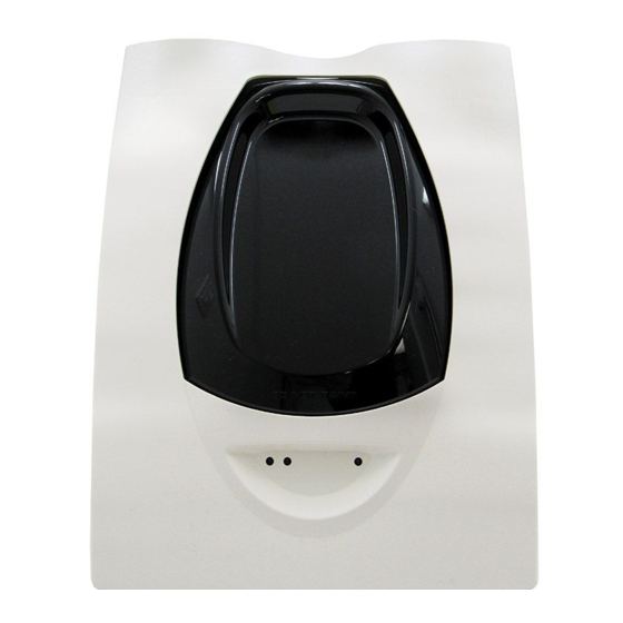
INSTALLATION AND MAINTENANCE INSTRUCTIONS
BEAM1224, BEAM1224S
Single-ended Reflected Type
Projected Beam Smoke Detector
Specifications
General
Range:
Sensitivity:
Spacing:
Response Time:
Trouble Conditions:
Test/Reset Features:
Indicators:
Environmental
Temperature:
Humidity:
Mechanical
Shipping Weight:
Shipping Size:
Mounting:
Wiring:
Adjustment Angle:
Paintable Trim Ring:
D400-73-00
16 to 230 Feet (5 to 70m)
230 to 328 Feet (70 to 100m) using optional accessory BEAMLRK
25% to 50% Total Obscuration in 6 levels
Level 1 = 25%
Level 2 = 30%
Level 3 = 40%
Level 4 = 50%
Level 5 = 30% to 50% (Acclimate)
Level 6 = 40% to 50% (Acclimate)
30 to 60 Feet (9.1 to 18.3m)
Alarm: 20 seconds typical
Trouble: 30 seconds typical
Beam Blockage (96% or More Obscuration)
Improper Initial Alignment
Self-compensation limit reached (service needed)
In Alignment mode
Integral Sensitivity Test Filter (BEAM1224S only)
Sensitivity Filter (Incremental scale on reflector)
Local Alarm Test Switch
Local Alarm Reset Switch
Remote Test and Reset Switch Capability
(compatible with RTS451/RTS451KEY)
Alarm:
Trouble:
Normal Operation:
Alignment Aids:
Relays:
Sensitivity:
–22°F to 131°F (–30°C to 55°C)
Note: For applications below 32°F (0°C), see Special Applications section of this manual
10% to 93% RH Noncondensing
Complete unit: 3.9 lbs. (1.77 kg)
15" × 10.5" × 6.5" (381mm × 267mm × 165mm)
Wall only without optional accessories
Plug-in Terminal Blocks (12 to 22AWG)
±10° Horizontal and Vertical
May be painted using enamel or acrylic type paints
Remote Output, Local LED (red)
Remote Output, Local LED (yellow)
Blink Pattern Indicates Trouble Diagnostics
Local LED (flashing green once every 5 sec.)
Optical Gunsight (coarse adjustment)
00 to 99 Digital Display (fine adjustment)
Alarm; Trouble
Digital Display Readout in Percent Obscuration
1
3825 Ohio Avenue, St. Charles, Illinois 60174
800/736-7672, FAX: 630/377-6495
www.systemsensor.com
I56-2294-03R
Advertisement
Table of Contents

Related Manuals for System Sensor BEAM1224


Summary of Contents for System Sensor BEAM1224
- Page 1 INSTALLATION AND MAINTENANCE INSTRUCTIONS BEAM1224, BEAM1224S Single-ended Reflected Type 3825 Ohio Avenue, St. Charles, Illinois 60174 800/736-7672, FAX: 630/377-6495 Projected Beam Smoke Detector www.systemsensor.com Specifications General Range: 16 to 230 Feet (5 to 70m) 230 to 328 Feet (70 to 100m) using optional accessory BEAMLRK...
-
Page 2: Before Installing
Alarm and Trouble outputs. These outputs mimic General Description the functions of the detector’s red and yellow LEDs. In System Sensor Model BEAM1224/BEAM1224S is a long addition to these indicators, there is a dual digital display range projected beam smoke detector designed to pro- that reads 00 to 99. - Page 3 (BEAMLRK). BEAMSMK can be addressed or minimized. The BEAMSMK allows System Sensor reflected beam detec- Some examples of applications for beam detectors might tors to be mounted when surface wiring is used. This kit...
-
Page 4: Detector Placement
(0.3-0.46m) Fire Alarm Code, as well as directives of the Authority Having Jurisdiction (AHJ). For general information on the placement of detectors, read System Sensor’s Projected Beam Detector Application Guide. Projected beam detectors are usually located with their beams parallel to the ceiling. However, they can be mount- WALL ed vertically or at any angle to protect the area involved. -
Page 5: Mounting Locations
Figure 3. Sloped ceiling (shed type): In cases where only one stable mounting surface as defined above can be used, the transmitter/receiver unit should be 3 f t . ( 0 . 9 m ) M a x . mounted to the stable surface and the reflector should be mounted to the less stable surface. -
Page 6: Mounting Considerations For Single Ended Beam Detectors
Where high ceilings (in excess of 30 feet or 9.1 meters) are present additional beams may be required to detect smoke at lower levels. See System Sensor’s Projected Beam Detector REFLECTOR Applications Guide for further explanation. - Page 7 Figure 7. Wiring Diagram BEAM1224 BEAM1224 T1-1 T1-3 T1-1 T1-3 Power+ Power IN+ Power OUT+ Power IN+ Power OUT+ T1-2 T1-4 T1-2 T1-4 Power– Power IN– Power OUT– Power IN– Power OUT– T4-2 T4-4 T4-2 T4-4 Initiating+ Alarm COM Alarm COM...
-
Page 8: Installation / Alignment
If the optics are incorrectly aligned in this step, it will not be possible to proceed with the fine The alignment of the BEAM1224/BEAM1224S is divided adjustment step. into four steps: coarse alignment, fine adjustment, final gain adjustment, and final verification. - Page 9 must be set by the operator. Periodically throughout the The final value of the display will not likely be near fine adjustment step the detector will need to re-adjust its 90. This is normal. It is due to the detector reduc- “electronic amplifier gain”...
- Page 10 NOTE: If the outer aesthetic ring has been painted insure Figure 11. Alignment Adjustment Locations that the paint is completely dry before proceeding ALIGNMENT MIRROR with this step. ALIGNMENT GUNSIGHT ALIGNMENT POSITION Step 4. Final Verification INDICATOR This step is required to insure the detector has been setup correctly and will detect smoke at the proper sensitivity level.
-
Page 11: Sensitivity Selection
To change the Detectors must be tested after installation and following sensitivity continue to depress the sensitivity switch until periodic maintenance. The sensitivity of the BEAM1224/ the desired setting is achieved. The digital display will turn BEAM1224S may be tested as follows: off automatically if no further switch presses occur. - Page 12 4. The detector can be reset with the reset switch on the Note: For the BEAM1224 this test does not satisfy the detector unit, remote reset, or momentarily interrupting requirements of NFPA72 for periodic maintenance and power.
-
Page 13: Maintenance
Maintenance If the detector fails this test several steps should be taken NOTE: Before cleaning the detector, notify the proper to determine if the detector is faulty or simply needs to be re-adjusted before returning the unit for repair. These steps authorities that the smoke detector system is include: undergoing maintenance, and therefore the sys-... -
Page 14: Appendix I. Operation Modes And Troubleshooting Guide
Appendix I. Operation Modes and Troubleshooting Guide Blinks output by Yellow LED and Remote Trouble Output once the device has passed a local remote test: Percent the Number detector has of blinks drifted output <10% None <20% <30% <40% <50% <60% <70% <80%... -
Page 15: Appendix Ii. Detector Drilling Template
Appendix II. Detector Drilling Template 6.190″ 4.345″ Scale = 1:1 D400-73-00 I56-2294-03R... - Page 16 D400-73-00 I56-2294-03R...
-
Page 17: Appendix Iii. Reflector Drilling Template
Appendix III. Reflector Drilling Template 5.512″ (140mm) 8.465″ (215mm) Scale = 1:1 D400-73-00 I56-2294-03R... -
Page 18: Three-Year Limited Warranty
Please include a note describing the malfunction and suspected cause period of three years from date of manufacture. System Sensor makes no of failure. The Company shall not be obligated to repair or replace units other express warranty for this smoke detector.
Need help?
Do you have a question about the BEAM1224 and is the answer not in the manual?
Questions and answers