Table of Contents
Advertisement
Quick Links
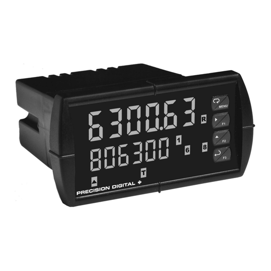
PD6300 Pulse Input Rate/Totalizer
Pulse, Open Collector, NPN, PNP, TTL, Switch Contact,
Sine Wave (Coil), Square Wave Inputs
Gate Function for Rate Display of Slow Pulse Rates
NEMA 4X, IP65 Front
Universal 85-265 VAC or 12/24 VDC Input Power
Large Dual-Line 6-Digit Display, 0.60" & 0.46"
Isolated 24 VDC @ 200 mA Transmitter Power Supply
Programmable Displays & Function Keys
Rate Displayed as Units per Second, Minute, Hour, or Day
Total, Grand Total or Non-Resettable Grand Total
9-Digit Totalizer with Total Overflow Feature
K-Factor Calibration or Scale with up to 32-Point Linearization
2 or 4 Relays + Isolated 4-20 mA Output for Rate or Total
External 4-Relays & Digital I/O Expansion Modules
RS-232 & RS-422/485 Serial Communication Options
®
Modbus
RTU Communication Protocol Standard
PRECISION DIGITAL CORPORATION
89 October Hill Road • Holliston MA 01746 USA
Tel (800) 343-1001 • Fax (508) 655-8990
Instruction Manual
www.predig.com
Advertisement
Table of Contents
Troubleshooting

Subscribe to Our Youtube Channel
Related Manuals for Precision Digital Corporation PD6300


Summary of Contents for Precision Digital Corporation PD6300
- Page 1 PD6300 Pulse Input Rate/Totalizer Instruction Manual Pulse, Open Collector, NPN, PNP, TTL, Switch Contact, Sine Wave (Coil), Square Wave Inputs Gate Function for Rate Display of Slow Pulse Rates NEMA 4X, IP65 Front Universal 85-265 VAC or 12/24 VDC Input Power ...
- Page 2 Anyone using this product for such applications does so at his/her own risk. Precision Digital Corporation shall not be held liable for damages resulting from such improper use. Limited Warranty Precision Digital Corporation warrants this product against defects in material or workmanship for the specified period under “Specifica-...
-
Page 3: Table Of Contents
Model PD6300 Pulse Input Rate/Totalizer Instruction Manual Table of Contents INTRODUCTION ------------------------------------------------------------- 7 ORDERING INFORMATION ---------------------------------------------- 8 SPECIFICATIONS ----------------------------------------------------------- 9 General ------------------------------------------------------------------------------- 9 Rate Input ------------------------------------------------------------------------- 10 Rate/Totalizer -------------------------------------------------------------------- 11 Relays ------------------------------------------------------------------------------ 12 ... - Page 4 Model PD6300 Pulse Input Rate/Totalizer Instruction Manual Reset Menu (reset) ------------------------------------------------------------ 36 Control Menu (Contrl) -------------------------------------------------------- 36 Setting Up the Rate/Totalizer Meter (setup) --------------------------- 37 Setting the Input Signal (Input) ------------------------------------------ 38 Setting the Totalizer Features (total) ---------------------------------- 38 ...
- Page 5 Model PD6300 Pulse Input Rate/Totalizer Instruction Manual Acknowledging Relays ------------------------------------------------------ 64 Setting Up the Interlock Relay Feature --------------------------------- 65 Scaling the 4-20 mA Analog Output (Aout) ---------------------------- 66 Setting Up the Password (pass) ------------------------------------------- 67 Protecting or Locking the Meter ------------------------------------------- 67 ...
- Page 6 Figure 4: Jumper Configuration for 12/24 VDC Power ..... 19 Figure 5: Transmitter Supply Voltage Selection ....... 20 Figure 6: Connector Labeling for Fully Loaded PD6300 ....21 Figure 7: Power Connections ............. 21 Figure 8: Flowmeter Powered by Internal Power Supply ....22 ...
-
Page 7: Introduction
24 VDC power supply is included with the 4-20 mA output option. A fully loaded PD6300 pulse rate/totalizer meter has the following: four SPDT relays, 4-20 mA output, and two 24 VDC power supplies. The PD6300 capabilities may be enhanced by adding the following external expansion modules: four SPST relays (creating an eight-relay rate/totalizer), two digital I/O modules with four inputs and four outputs each, and RS-232 or RS-485 communication adapters. -
Page 8: Ordering Information
Model PD6300 Pulse Input Rate/Totalizer Instruction Manual ORDERING INFORMATION Standard Models 85-265 VAC 12/24 VDC Options Installed Model Model PD6300-6R0 PD6300-7R0 No options PD6300-6R2 PD6300-7R2 2 relays (PD1102*) PD6300-6R3 PD6300-7R3 4-20 mA output (PD1103*) PD6300-6R4 PD6300-7R4 4 relays (PD1104*) PD6300-6R5 PD6300-7R5 2 relays &4-20 mA output (PD1105*) -
Page 9: Specifications
Model PD6300 Pulse Input Rate/Totalizer Instruction Manual SPECIFICATIONS Except where noted all specifications apply to operation at +25°C. General DISPLAY Main display: 0.6" (15 mm) high, red LEDs Second display: 0.46" (12 mm) high, red LEDs 6 digits: each (-99999 to 999999), with lead zero blanking. -
Page 10: Rate Input
Model PD6300 Pulse Input Rate/Totalizer Instruction Manual OVERVOLTAGE Installation Overvoltage Category II: CATEGORY Local level with smaller transient overvoltages than Installa- tion Overvoltage Category III. ENVIRONMENTAL Operating temperature range: -40 to 65°C Storage temperature range: -40 to 85°C Relative humidity: 0 to 90% non-condensing... -
Page 11: Rate/Totalizer
Model PD6300 Pulse Input Rate/Totalizer Instruction Manual DECIMAL POINT Up to five decimal places or none: d. d dddd, d. d ddd, d. d dd, d. d d, d. d , dddddd CALIBRATION May be calibrated using K-factor, internal calibration, or by applying an external calibration signal. -
Page 12: Relays
Model PD6300 Pulse Input Rate/Totalizer Instruction Manual TOTAL Program total reset for automatic with 0.1 second delay and OVERFLOW set point 1 for 999,999 OVERRIDE TOTALIZER Up to eight, user selectable under setup menu. Any set PRESETS point can be assigned to total and may be programmed anywhere in the range of the meter for total alarm indica- tion. -
Page 13: Isolated 4-20 Ma Transmitter Output
Model PD6300 Pulse Input Rate/Totalizer Instruction Manual RELAY RESET User selectable via front panel buttons, digital inputs, or PC Automatic reset only (non-latching), when the in- put passes the reset point or total is reset to zero. Automatic + manual reset at any time (non-latching) -
Page 14: Modbus ® Rtu Serial Communications
Model PD6300 Pulse Input Rate/Totalizer Instruction Manual ® Modbus RTU Serial Communications SLAVE ID 1 – 247 (Meter address) BAUD RATE 300 - 19,200 bps TRANSMIT Programmable between 0 and 199 ms TIME DELAY or transmitter always on for RS-422 communication... -
Page 15: Compliance Information
Model PD6300 Pulse Input Rate/Totalizer Instruction Manual COMPLIANCE INFORMATION Safety UL & c-UL LISTED USA & Canada UL 508 Industrial Control Equipment UL FILE NUMBER E160849 FRONT PANEL UL Type 4X, NEMA 4X, IP65; panel gasket provided LOW VOLTAGE EN 61010-1:2001... -
Page 16: Safety Information
Model PD6300 Pulse Input Rate/Totalizer Instruction Manual Note: Testing was conducted on PD6300 meters installed through the cov- ers of grounded metal enclosures with cable shields grounded at the point of entry representing installations designed to optimize EMC performance. Declaration of Conformity available at www.predig.com... -
Page 17: Installation
Model PD6300 Pulse Input Rate/Totalizer Instruction Manual INSTALLATION There is no need to remove the meter from its case to complete the installation, wiring, and setup of the meter for most applica- tions. Instructions are provided for setting up a 12/24 VDC po-... -
Page 18: Figure 2: Meter Dimensions - Side View
Model PD6300 Pulse Input Rate/Totalizer Instruction Manual Mounting Dimensions 1.76" (45 mm) 2.45" (62 mm) 4.77" 0.59" (121 mm) (15 mm) 5.05" (128 mm) Figure 2: Meter Dimensions - Side View 4.17" (106 mm) 3.61" (92 mm) 4.68" (119 mm) -
Page 19: Configuration For 12 Or 24 Vdc Power Option
Model PD6300 Pulse Input Rate/Totalizer Instruction Manual Configuration for 12 or 24 VDC Power Option Do not exceed voltage rating of the selected configuration. Warning! Meters equipped with the 12/24 VDC power option are shipped from the factory ready to operate from 24 VDC. -
Page 20: Transmitter Supply Voltage Selection (P+, P-)
Model PD6300 Pulse Input Rate/Totalizer Instruction Manual Transmitter Supply Voltage Selection (P+, P-) All meters, including models equipped with the 12/24 VDC power option, are shipped from the factory configured to provide 24 VDC power for the transmitter or sensor. -
Page 21: Connectors Labeling
RJ45 M-LINK connector. Otherwise damage will occur Warning! to the equipment and the meter. Figure 6: Connector Labeling for Fully Loaded PD6300 Power Connections Power connections are made to a two-terminal connector labeled POWER on Figure 6. The meter will operate regardless of DC polarity connection. -
Page 22: Signal Connections
Model PD6300 Pulse Input Rate/Totalizer Instruction Manual Signal Connections Signal connections are made to a five-terminal connector labeled SIGNAL on Figure 6. The COM (common) terminal is the return for the input signals. The following figures show examples of signal connections. - Page 23 Model PD6300 Pulse Input Rate/Totalizer Instruction Manual INPUT SIGNAL +5 V 4.7 k-ohm Internal pull-up PNP NPN LEVEL TYPE SENSOR Figure 11: NPN open Collector Input INPUT SIGNAL 4.7 k-ohm Internal pull-down PNP NPN LEVEL TYPE SENSOR Figure 12: PNP Sensor Powered by Internal Supply...
-
Page 24: Modbus Rtu Serial Communications
Model PD6300 Pulse Input Rate/Totalizer Instruction Manual Modbus RTU Serial Communications Serial communications connection is made to an RJ45 connector labeled M-LINK on Figure 6. Use the PDA1232 for RS-232 interfacing or the PDA1485 for RS-422/485 interfacing. The same port is used for interfac- ing with all expansion modules (e.g. -
Page 25: Switching Inductive Loads
Model PD6300 Pulse Input Rate/Totalizer Instruction Manual Switching Inductive Loads The use of suppressors (snubbers) is strongly recommended when switching inductive loads to prevent disrupting the microprocessor’s op- eration. The suppressors also prolong the life of the relay contacts. Sup- pression can be obtained with resistor-capacitor (RC) networks assem- bled by the user or purchased as complete assemblies. -
Page 26: 4-20 Ma Output Connections
Model PD6300 Pulse Input Rate/Totalizer Instruction Manual 4-20 mA Output Connections Connections for the 4-20 mA transmitter output are made to the connec- tor terminals labeled MA OUT. The 4-20 mA output may be powered internally or from an external power supply. -
Page 27: External Relay & Digital I/O Connections
Model PD6300 Pulse Input Rate/Totalizer Instruction Manual External Relay & Digital I/O Connections The relay and digital I/O expansion modules PDA1004 & PDA1044 are connected to the meter using the CAT5 cable provided with each mod- ule. The two RJ45 connectors on the expansion modules are identical and interchangeable;... -
Page 28: Interlock Relay Feature
Model PD6300 Pulse Input Rate/Totalizer Instruction Manual DI 1-4 DO 1-4 5 VDC Figure 17: Digital I/O Module Connections Interlock Relay Feature As the name implies, the interlock relay feature reassigns one, or more, alarm/control relays for use as interlock relay(s). Interlock contact(s) are wired to digital input(s) and trigger the interlock relay. -
Page 29: Setup And Programming
Model PD6300 Pulse Input Rate/Totalizer Instruction Manual SETUP AND PROGRAMMING The meter has been factory calibrated to read input frequency in Hz (pulses/sec). The calibration equip- ment is certified to NIST standards. Use the K-Factor menu to match the rate/totalizer with a flowmeter’s k-factor (pulse/unit of measure). -
Page 30: Front Panel Buttons And Status Led Indicators
Model PD6300 Pulse Input Rate/Totalizer Instruction Manual Front Panel Buttons and Status LED Indicators Button Description Status Symbol Menu Alarm 1 – 8 indicator Right arrow/F1 Rate indicator Up arrow/F2 Total indicator Enter/F3 Grand Total indicator Note: Total overflow ▲... -
Page 31: Display Functions And Messages
Model PD6300 Pulse Input Rate/Totalizer Instruction Manual Display Functions and Messages The meter displays various functions and messages during setup, pro- gramming, and operation. The following table shows the main menu functions and messages in the order they appear in the menu. - Page 32 Model PD6300 Pulse Input Rate/Totalizer Instruction Manual Display Parameter Action/Setting Description Assignment Assign relays to rate, total, or grand total Assign Relay 1 assignment Asign1 Assign 1 Rate Assign relay to rate rATE Total Assign relay to total totAL Grand total...
- Page 33 Model PD6300 Pulse Input Rate/Totalizer Instruction Manual Display Parameter Action/Setting Description Fail-safe off Disable fail-safe operation Enter relay Time Delay menu DeLAY Delay Delay 1 Enter relay 1 time delay setup DLY 1 Set relay 1 On time delay On 1...
- Page 34 Model PD6300 Pulse Input Rate/Totalizer Instruction Manual Display Parameter Action/Setting Description Total reset Program total reset mode: auto or manual T rst Program grand total time base GT tb Grand total time base Grand total Program grand total conversion factor...
-
Page 35: Main Menu
Model PD6300 Pulse Input Rate/Totalizer Instruction Manual Main Menu The main menu consists of the most commonly used functions: Reset, Control, Setup , Program , and Password . Press Menu button to enter Programming Mode then press the Up arrow button to scroll through the main menu. -
Page 36: Setting Numeric Values
Model PD6300 Pulse Input Rate/Totalizer Instruction Manual Setting Numeric Values The numeric values are set using the Right and Up arrow buttons. Press the Right arrow to select the next digit and Up arrow to increment digit value. The digit being changed is displayed brighter than the rest. -
Page 37: Setting Up The Rate/Totalizer Meter (Setup)
Model PD6300 Pulse Input Rate/Totalizer Instruction Manual Setting Up the Rate/Totalizer Meter (setup) The Setup menu is used to select: Enable or disable totalizer features Decimal point position Display parameter and intensity Relay operation 4-20 mA analog output scaling Press the Enter button to access any menu or press Up arrow button to scroll through choices. -
Page 38: Setting The Input Signal (Input)
Model PD6300 Pulse Input Rate/Totalizer Instruction Manual Setting the Input Signal (Input) There are two switches, located to the right of the input connector, which must be configured according to the input level and type. Jumper J4 lo- cated inside the meter, behind the input signal connector, is used to se- lect the excitation voltage (24 V*, 10 V or 5 V) which is supplied to the P+ and P- wiring terminals. -
Page 39: Setting The Display Parameter & Intensity (Dsplay)
Model PD6300 Pulse Input Rate/Totalizer Instruction Manual Setting the Display Parameter & Intensity (dsplay) The main display ( Big ) can be programmed to display: Rate value Total or grand total Relay set points Max & min values Modbus input... -
Page 40: Display Setup Menu
Model PD6300 Pulse Input Rate/Totalizer Instruction Manual Display Setup Menu Dsplay Little d-Inty setup dsplay dsplay dsplay Rate Total d rate Grand total Batch b i g d-Inty dset 1 d tot Little b i g d-Inty d Hi d Gtot... -
Page 41: Character Set For Engineering Units Display (D Unit)
Model PD6300 Pulse Input Rate/Totalizer Instruction Manual Character Set for Engineering Units Display (d unit) The small display can be programmed to show engineering units or cus- tom legends using the following 7-segment character set: Display Character Display Character Space <*... -
Page 42: Programming The Rate/Totalizer (Prog)
Model PD6300 Pulse Input Rate/Totalizer Instruction Manual Programming the Rate/Totalizer (prog) It is very important that one reads the following information before pro- gramming the meter: The meter has been factory calibrated to read input frequency in Hz (pulses/sec). The calibration equipment is certified to NIST stan- dards. -
Page 43: K-Factor Calibration (Factor)
Model PD6300 Pulse Input Rate/Totalizer Instruction Manual K-Factor Calibration (Factor) The meter may be calibrated using the K-Factor function. Most flowmeter manufacturers provide this information with the device. Enter the K-Factor ( Factor ) menu and select the decimal point with highest reso- lution possible and program the k-factor value ( i.e. -
Page 44: Meterview ® Pro Software
Model PD6300 Pulse Input Rate/Totalizer Instruction Manual ® MeterView Pro Software The meter can also be programmed using the PC-based MeterView Pro software available for free download at www.predig.com. Data logging for one meter at the time is available with MeterView Pro software. -
Page 45: Scaling The Meter (Scale)
Model PD6300 Pulse Input Rate/Totalizer Instruction Manual Scaling the Meter (SCALE) The pulse inputs can be scaled to display the process variable in engi- neering units. A signal source is not needed to scale the meter; simply program the inputs and corresponding display values. -
Page 46: Gate Function (Gate)
Model PD6300 Pulse Input Rate/Totalizer Instruction Manual Error Message (Error) An error message indicates that the calibration or scaling process was not successful. After the error message is displayed, the meter reverts to input 2 during calibration or scaling, allowing the appropriate input signal to be applied or programmed. -
Page 47: Contact De-Bounce Filter (Filter)
Model PD6300 Pulse Input Rate/Totalizer Instruction Manual Gate Settings Slow Pulse Rate Low Gate* (sec) High Gate (sec) Min Freq** (Hz) 0.5000 10.0 0.1000 20.0 0.0500 100.0 0.0100 200.0 0.0050 400.0 0.0025 800.0 0.0012 999.9 0.0010 *The low gate setting corresponds to the display update rate and is used to stabilize the display reading with a fluctuating signal. -
Page 48: Time Base, Total Conversion Factor & Total Reset
Model PD6300 Pulse Input Rate/Totalizer Instruction Manual Time Base, Total Conversion Factor & Total Reset The time base, total conversion factor, and total reset menus are located in the Program menu. The total and grand total have their own independent settings. This... -
Page 49: Calibrating The Meter With External Source (Cal)
Model PD6300 Pulse Input Rate/Totalizer Instruction Manual Calibrating the Meter with External Source (Cal) To scale the meter without a signal source refer to K-Factor Calibration ( Factor ) on page 43 or Scaling the Meter ( SCALE ) on page 45... -
Page 50: Setting The Relay Operation (Relay)
Model PD6300 Pulse Input Rate/Totalizer Instruction Manual Setting the Relay Operation (relay) This menu is used to set up the operation of the relays. CAUTION! During setup, the relays do not follow the input and they will remain in the state found prior to entering the Relay menu. -
Page 51: Relay Assignment (Assign)
Model PD6300 Pulse Input Rate/Totalizer Instruction Manual relay setup Assign Failsf delay relay relay relay relay Asign1 A s s i g n r l y 1 F a i l s f delay rly 1 F l s 1... -
Page 52: Setting The Relay Action
Model PD6300 Pulse Input Rate/Totalizer Instruction Manual Setting the Relay Action Operation of the relays is programmed in the Action menu. The relays may be set up for any of the following modes of operation: Automatic reset (non-latching) Automatic + manual reset at any time (non-latching) -
Page 53: Programming Set And Reset Points
Model PD6300 Pulse Input Rate/Totalizer Instruction Manual Programming Set and Reset Points High alarm indication: program set point above reset point. Low alarm indication: program set point below reset point. The deadband is determined by the difference between set and reset points. -
Page 54: Relay And Alarm Operation Diagrams
Model PD6300 Pulse Input Rate/Totalizer Instruction Manual Relay and Alarm Operation Diagrams The following graphs illustrate the operation of the relays, status LEDs, and ACK button. High Alarm Operation (Set > Reset) Input Reset de-energized energized Relay Automatic (non-latching) Relay... -
Page 55: Low Alarm Operation (Set < Reset)
Model PD6300 Pulse Input Rate/Totalizer Instruction Manual Low Alarm Operation (Set < Reset) Input Reset de-energized energized Relay Automatic (non-latching) Relay pressed Automatic or Manual (non-latching) Relay pressed Manual (latching) Relay pressed Manual only after passing above Reset (latching with clear) For Manual reset mode, ACK can be pressed anytime to turn "off"... -
Page 56: High Alarm With Fail-Safe Operation (Set > Reset)
Model PD6300 Pulse Input Rate/Totalizer Instruction Manual High Alarm with Fail-Safe Operation (Set > Reset) Input Reset de-energized energized Relay Automatic (non-latching) Relay pressed Automatic or Manual (non-latching) Relay pressed Manual (latching) Relay pressed Manual only after passing below Reset (latching with clear) Note: Relay coil is energized in non-alarm condition. -
Page 57: Low Alarm With Fail-Safe Operation (Set < Reset)
Model PD6300 Pulse Input Rate/Totalizer Instruction Manual Low Alarm with Fail-Safe Operation (Set < Reset) Input Reset de-energized energized Relay Automatic (non-latching) Relay pressed Automatic or Manual (non-latching) Relay pressed Manual (latching) Relay pressed Manual only after passing above Reset (latching with clear) Note: Relay coil is energized in non-alarm condition. -
Page 58: Alternation Control Operation
Model PD6300 Pulse Input Rate/Totalizer Instruction Manual... -
Page 59: Rate Relay Sampling Operation
Model PD6300 Pulse Input Rate/Totalizer Instruction Manual Rate Relay Sampling Operation Input Reset Sample Sample Sample Time Time Time Relay When the signal crosses the set point, the relay trips and the sample time starts. After the sample time has elapsed, the relay resets. The cycle repeats every time the set point is crossed, going up for high alarms and going down for low alarms. -
Page 60: Time Delay Operation
Model PD6300 Pulse Input Rate/Totalizer Instruction Manual Time Delay Operation The following graphs show the operation of the time delay function. Input Reset <Tdelay <Tdelay >=Tdelay Relay On Time Delay Input Reset <Tdelay <Tdelay >=Tdelay Relay Off Time Delay When the signal crosses the set point, the On time delay timer starts and the relay trips when the time delay has elapsed. -
Page 61: Relay Operation Details
Model PD6300 Pulse Input Rate/Totalizer Instruction Manual Relay Operation Details Overview The relay capabilities of the meter expand its usefulness beyond simple indication to provide users with alarm and control functions. These capa- bilities include front panel alarm status LEDs as well as either 2 or 4 op- tional internal relays and/or 4 external relays expansion module. -
Page 62: Front Panel Leds
Model PD6300 Pulse Input Rate/Totalizer Instruction Manual Front Panel LEDs The LEDs on the front panel provide status indication for the following: Status Status Alarm 1 Alarm 5 Alarm 2 Alarm 6 Alarm 3 Alarm 7 Alarm 4 Alarm 8 The meter is supplied with four alarm points that include front panel LEDs to indicate alarm conditions. -
Page 63: Non-Latching Relay (Auto)
Model PD6300 Pulse Input Rate/Totalizer Instruction Manual Non-Latching Relay (Auto) Automatic reset only Condition Relay Normal Alarm Ack (No effect) Normal In this application, the meter is set up for automatic reset (non-latching relay). Acknowledging the alarm while it is still present has no effect on either the LED or the relay. -
Page 64: Latching Relay (Lt-Clr)
Model PD6300 Pulse Input Rate/Totalizer Instruction Manual Latching Relay (Lt-Clr) Manual reset only after alarm condition has cleared Condition Relay Normal Alarm Ack (No effect) Normal In this application, the meter is set up for manual reset only after the signal passes the reset point (alarm condition has cleared). -
Page 65: Setting Up The Interlock Relay Feature
Model PD6300 Pulse Input Rate/Totalizer Instruction Manual Setting Up the Interlock Relay Feature Relays 1-4 can be set up as interlock relays. To set up the relays for the interlock feature: 1. Access the Setup – Relay – Action menu and set the action to off. -
Page 66: Scaling The 4-20 Ma Analog Output (Aout)
Model PD6300 Pulse Input Rate/Totalizer Instruction Manual Scaling the 4-20 mA Analog Output (Aout) The 4-20 mA analog output can be scaled to provide a 4-20 mA signal for any display range selected. No equipment is needed to scale the analog output; simply program the display values to the corresponding mA output signal. -
Page 67: Setting Up The Password (Pass)
Model PD6300 Pulse Input Rate/Totalizer Instruction Manual Setting Up the Password (pass) The Password menu is used for programming three levels of security to prevent unauthorized changes to the programmed parameter settings and to program the non-resettable totalizer. Pass 1: Allows use of function keys and digital inputs Pass 2: Allows use of function keys, digital inputs and editing set/reset points Pass 3: Restricts all programming, function keys, and digital inputs. -
Page 68: Total Reset Password & Non-Resettable Total
Model PD6300 Pulse Input Rate/Totalizer Instruction Manual Total Reset Password & Non-Resettable Total The total and the grand total can be password-protected to pre- vent unauthorized total resets. The grand total can be programmed as a non-resettable total by entering the password “050873”. -
Page 69: Making Changes To A Password Protected Meter
Model PD6300 Pulse Input Rate/Totalizer Instruction Manual Making Changes to a Password Protected Meter If the meter is password protected, the meter will display the message Locd ( Locked ) when the Menu button is pressed. Press the Enter button while the message is being displayed and enter the correct password to gain access the menu. -
Page 70: Advanced Features Menu
Model PD6300 Pulse Input Rate/Totalizer Instruction Manual Advanced Features Menu To simplify the setup process, functions not needed for most applications are located in the Advanced Features menu. Press and hold the Menu button for three seconds to access the ad- vanced features of the meter. -
Page 71: Advanced Features Menu & Display Messages
Model PD6300 Pulse Input Rate/Totalizer Instruction Manual Advanced Features Menu & Display Messages The following table shows the functions and messages of the Advanced Features menu in the order they appear in the menu. Display Parameter Action/Setting Gate Enter Gate function menu... - Page 72 Model PD6300 Pulse Input Rate/Totalizer Instruction Manual Display Parameter Action/Setting O-rang Overrange Program mA output for display overrange Program mA output for display underrange u-rang Underrange Maximum Program maximum mA output allowed nmAx Program minimum mA output allowed nmin Minimum...
- Page 73 Model PD6300 Pulse Input Rate/Totalizer Instruction Manual Display Parameter Action/Setting Cutoff Cutoff Cutoff value Set time period T tb Total time base Total conver- Set conversion factor T CF sion factor Total reset Set reset method T rst Grand total...
-
Page 74: Modbus Rtu Serial Communications (Serial)
0 and 199 ms. The parity can be set to even, odd, or none with 1 or 2 stop bits. The PD6300 can also be connected to another PD6300 with a special PDA1200 cable, allowing the user to copy all the settings from one meter... -
Page 75: Select Menu (Select)
Model PD6300 Pulse Input Rate/Totalizer Instruction Manual Select Menu (SElEct) The Select menu is used to select the math function applied to the input (linear), low-flow cutoff, and analog output programming. The multi-point linearization is part of the linear function selection. - Page 76 Square Root Linearization (Square) Note: Although this option may appear in the menu the functionality is not available in the PD6300 series products. Programmable Exponent Linearization (Prog E) Note: Although this option may appear in the menu the functionality is not available in the PD6300 series products.
-
Page 77: Low-Flow Cutoff (Cutoff)
Model PD6300 Pulse Input Rate/Totalizer Instruction Manual Low-Flow Cutoff (CutofF) The low-flow cutoff feature allows the meter to be programmed so that the often-unsteady output from a differential pressure transmitter, at low flow rates, always displays zero on the meter. -
Page 78: Programmable Function Keys User Menu (User)
Model PD6300 Pulse Input Rate/Totalizer Instruction Manual Programmable Function Keys User Menu (user) The User menu allows the user to assign the front panel function keys F1, F2, F3 and up to eight digital inputs to access most of the menus or to activate functions immediately (e.g. -
Page 79: Meter Copy Function (Copy)
Model PD6300 Pulse Input Rate/Totalizer Instruction Manual Meter Copy Function (Copy) The Copy function is used to copy (or clone) all the settings from one meter to other meters requiring exactly the same setup and program- ming ( i.e . type of input, scaling, decimal point, filter, gate, etc.). - Page 80 Model PD6300 Pulse Input Rate/Totalizer Instruction Manual Meter Copy or Cloning Instructions Do not connect the two meters to the same signal source while cloning. Internal calibration may Caution! be affected. Connect two meters using a PDA1200 meter copy cable.
-
Page 81: Meter Operation
Model PD6300 Pulse Input Rate/Totalizer Instruction Manual METER OPERATION The meter accepts pulses (e.g. ±40mV to ± 8V), square wave (0-5, 0- 12V, or 0-24V), open collector NPN, PNP, TTL, or switch contact signals and displays these signals in engineering units from -99999 to 999999. -
Page 82: Maximum/Minimum Readings
Model PD6300 Pulse Input Rate/Totalizer Instruction Manual Maximum/Minimum Readings The max & min readings (peak & valley) reached by the process can be displayed either continuously or momentarily: Display briefly by assigning to the F1-F3 function keys or to the digi- tal inputs in the User menu. -
Page 83: Troubleshooting
Model PD6300 Pulse Input Rate/Totalizer Instruction Manual TROUBLESHOOTING The rugged design and the user-friendly interface of the meter should make it unusual for the installer or operator to refer to this section of the manual. However, due to the many features and functions of the meter, it’s possible that the setup of the meter does not agree with what an op-... -
Page 84: Reset Meter To Factory Defaults
Model PD6300 Pulse Input Rate/Totalizer Instruction Manual Reset Meter to Factory Defaults When the parameters have been changed in a way that is difficult to determine what’s happening, it might be better to start the setup process from the factory defaults. -
Page 85: Factory Defaults & User Settings
Model PD6300 Pulse Input Rate/Totalizer Instruction Manual Factory Defaults & User Settings The following table shows the factory setting for most of the programma- ble parameters on the meter. Next to the factory setting, the user may record the new setting for the particular application. - Page 86 Model PD6300 Pulse Input Rate/Totalizer Instruction Manual Parameter Display Default Setting User Setting Relay 3 assignment Rate Asign3 Relay 4 assignment Rate Asign4 Relay 1 action Automatic Act 1 Relay 1 set point 100.0 Set 1 Relay 1 reset point 000.0...
- Page 87 Model PD6300 Pulse Input Rate/Totalizer Instruction Manual Parameter Display Default Setting User Setting Source analog output Rate/process Source Overrange output 21.000 mA O-rang Underrange output u-rang 3.000 mA Maximum output nmAx 23.000 mA Minimum output 0.000 mA nmin Slave ID (Address)
-
Page 88: Troubleshooting Tips
Model PD6300 Pulse Input Rate/Totalizer Instruction Manual Troubleshooting Tips Symptom Check/Action Check power at power connector No display at all Meter is password-protected, enter Not able to change setup or pro- correct six-digit password to unlock gramming, Locd is displayed... -
Page 89: Alphabetical List Of Display Functions & Messages
Model PD6300 Pulse Input Rate/Totalizer Instruction Manual Alphabetical List of Display Functions & Messages Display Parameter Action/Setting Description 20 mA output Enter mA output value read by milliamp 20 nmA meter with at least 0.001 mA resolution 4 nmA 4 mA output Enter mA output value read by milliamp meter with at least 0.001 mA resolution... - Page 90 Model PD6300 Pulse Input Rate/Totalizer Instruction Manual Display Parameter Action/Setting Description Calibrate Calibrate 4-20 mA output (internal refer- Calib ence source used for scaling the output) Contrl Control Enter Control menu Copy Enter copy function Copy Cutoff Cutoff value Cutoff...
- Page 91 Model PD6300 Pulse Input Rate/Totalizer Instruction Manual Display Parameter Action/Setting Description Display set 1 Select to display set point 1 (1-8) DSet 1 Display Enter the Display menu dsplay Enter Button Assign digital input to Enter button Enter Error Error...
- Page 92 Model PD6300 Pulse Input Rate/Totalizer Instruction Manual Display Parameter Action/Setting Description Latching Set relay for latching operation (relays as- LatCH signed to rate) LED t LED test Test all LEDs Length Not applicable Length Linear Set meter for linear function and select...
- Page 93 Model PD6300 Pulse Input Rate/Totalizer Instruction Manual Display Parameter Action/Setting Description Set relay 1 On time delay On 1 Overrange Program mA output for display overrange O-rang Output 1 Program output 1 value (e.g. 4.000 mA) Out 1 Out 2 Output 2 Program output 2 value (e.g.
- Page 94 Model PD6300 Pulse Input Rate/Totalizer Instruction Manual Display Parameter Action/Setting Description Reset Total Reset total Rst t Sampling Set relay for sampling operation Sanmpl Scale Enter the Scale menu sCalE SelEct Select Enter the Select menu (function, cutoff, out) send...
- Page 95 Model PD6300 Pulse Input Rate/Totalizer Instruction Manual NOTES...
- Page 96 Model PD6300 Pulse Input Rate/Totalizer Instruction Manual How to Contact Precision Digital For Technical Support please Call: (800) 610-5239 or (508) 655-7300 Fax: (508) 655-8990 Email: support@predig.com For Sales Support or to place an order please Call: (800) 343-1001 or (508) 655-7300 Fax: (508) 655-8990 Email: sales@predig.com...
Need help?
Do you have a question about the PD6300 and is the answer not in the manual?
Questions and answers