Table of Contents
Advertisement
Quick Links
D I G I T A L P A N E L M E T E R S
Models PD696 - PD698
6 Digit Loop-Powered Flow Rate/Totalizers
Instruction Manual
PD698
Explosion-Proof Enclosure
Available with
Loop-Powered
Backlight
• 4-20 mA Linear or Square Root Input
• 4½ Digit Rate Display, 6 Digit Total Display
• Total Displayed in any Engineering Unit
• Rate Displayed in Engineering Units per Second, Minute, or Hour
• Programmable Alternating Rate/Total Display
• Low-Flow Cutoff
• Field Selectable Noise Filter
• Non-Volatile Memory, No Battery Needed
• Isolated Open Collector Pulse Output
• Loop-Powered Backlight Option
PRECISION DIGITAL CORPORATION
19 Strathmore Road • Natick MA 01760 USA
Tel (800) 610-5239 • Fax (508) 655-8990
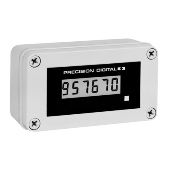
PD697
NEMA 4X Enclosure
PD696
1/8 DIN Panel Mount
www.predig.com
Advertisement
Table of Contents

Subscribe to Our Youtube Channel
Related Manuals for Precision Digital Corporation PD696


Summary of Contents for Precision Digital Corporation PD696
- Page 1 D I G I T A L P A N E L M E T E R S Models PD696 - PD698 6 Digit Loop-Powered Flow Rate/Totalizers Instruction Manual PD697 NEMA 4X Enclosure PD698 Explosion-Proof Enclosure Available with Loop-Powered PD696...
-
Page 2: Table Of Contents
Models PD696 – PD698 Instruction Manual TABLE OF CONTENTS Specifications Setup and Programming Overview Connections Programming Calibration Low-Flow Cutoff (CutoFF) Noise Filter Totalizer Programming Time Base (t bASE) Totalizer Conversion Factor (tot CF) Totalizer Decimal Point (tot dP) Parameter Combinations... - Page 3 They are available in three enclosure types with or without the loop-powered backlight option. 1/8 DIN Panel Mount The PD696 is housed in a standard 1/8 DIN panel mount enclosure with a NEMA 4X front panel. NEMA 4X Enclosure...
-
Page 4: Specifications
Minimum Input Span: 1.6 mA between Input 1 and Input 2. An Error message will appear if Input 1 and Input 2 signals are programmed too close together. Programming Method: PD696 & PD697: one front panel button; PD698: one button behind faceplate or reed switch & magnet. -
Page 5: Setup And Programming Overview
Models PD696 – PD698 Instruction Manual PD696 Enclosure: 1/8 DIN, high impact plastic, UL 94V-0; color: black; NEMA 4X, IP65 front panel; panel gasket provided PD696 Weight: 6.9 oz (196 g) PD697 Enclosure: Impact-resistant glass filled polycarbonate, color: gray, NEMA 4X, IP67; ½" conduit hole provided at base. May be provided on back for panel mounting applications, call factory for details. - Page 6 ATTENTION: OUVRIR LE CIRCUIT AVANT D’ENLEVEL LE COUVERCLE GARDER LE COUVERCLE BIEN FERME TANT QUE LES CIRCUITS SONT SOUS TENSION. UN SCELLEMENT DOIT ETRE INSTALLE A MOINS DE 450 mm DU BOITIER. Note: The PD696 screw terminal connector is located at the back of the instrument.
-
Page 7: Connections
Models PD696 – PD698 Instruction Manual CONNECTIONS Note: When using a four-wire transmitter connect the transmitter’s positive signal terminal to S+ and the negative signal to S-. WIRING INSTRUCTIONS CAUTION : Use supply wires suitable for 5 degrees C above surrounding ambient. -
Page 8: Programming
CALIb, CutoFF, FILtEr, t bASE, tot CF, tot dP, PuLSE, dSPLAy, and ContSt. The following flowchart overviews the PD696 - PD698 programming routines. Push front button Display scrolls programming routines. Push front panel button to select desired routine... - Page 9 Models PD696 – PD698 Instruction Manual Display Functions and Messages Display Parameter Description Display Total Sets the total as the default display (page 18) dSPy t Display Rate Sets the rate as the default display (page 18) dSPy r rSEt t...
-
Page 10: Calibration
Models PD696 – PD698 Instruction Manual CALIBRATION Calibration is performed using the front panel button. It does not require any tools or disassembly of the meter. A calibrated signal source is required. The calibration input signals must be within the range of the meter and there must be an absolute difference between Input 1 and Input 2 greater than 1.6 mA. -
Page 11: Low-Flow Cutoff (Cutoff)
Instruction Manual LOW-FLOW CUTOFF (CutoFF) The Low-Flow Cutoff allows the PD696 Series to be programmed so that the often unsteady output from a differential pressure transmitter at low flow rates always displays a zero on the rate display. Factory default is 000000 (disabled). - Page 12 Models PD696 – PD698 Instruction Manual Program Noise Filter and Noise Filter Bypass value Push the front panel button, when FILtEr appears push the button again. All digits flash for 3 seconds. If this is the desired filter value push the button before the entire display stops flashing.
-
Page 13: Totalizer Programming
Models PD696 – PD698 Instruction Manual TOTALIZER PROGRAMMING TIME BASE (t bASE) The meter must be programmed with the time base. The Time Base is the time unit in which the rate is displayed. For example, if the rate display is set up for gallons per hour then the time base must be set to hours. -
Page 14: Totalizer Decimal Point (Tot Dp)
Models PD696 – PD698 Instruction Manual TOTALIZER DECIMAL POINT (tot dP) The decimal point for the totalization display is field selectable and can be placed at any position. To set Totalizer Decimal Point Push the front panel button, when tot dP appears push the button again. -
Page 15: Isolated Pulse Output (Pulse)
ISOLATED PULSE OUTPUT (PuLSE) The isolated pulse output signal can be programmed to produce 1 pulse output per any accumulated total between 1 and 999. For example, the PD696-PD698 can be programmed to produce one pulse for every 500 gallons totalized. -
Page 16: Display Contrast (Contst)
The PD696’s JP1 jumper is located at rear of instrument. The PD697’s and PD698’s JP1 jumper is located on the top of the display board. - Page 17 Models PD696 – PD698 Instruction Manual Alternating Display The display may be programmed to alternate between rate and total every 10 seconds. To automatically alternate between rate and total select no for both dSPy r and dSPy t (see Display Selection (dSPLAy) above).
-
Page 18: Operation
Models PD696 – PD698 Instruction Manual OPERATION DEFAULT DISPLAY (DSPLY T or DSPLY R) If the meter is programmed for manual display, the user may select either rate or total to be set as the default displayed reading. When displaying rate an “r”... -
Page 19: Installation
Models PD696 – PD698 Instruction Manual INSTALLATION PD696 Panel Mount Panel Thickness 4.25" (108 mm) 0.125" - 0.250" (3.2 - 6.4 mm) 2.30" (59 mm) 4.30" (109 mm) 6" (152 mm) Clearance Installed 4.83" (123 mm) 0.575" (14.6 mm) Required for Installation Notes: Panel cutout required: 1.772"... - Page 20 Models PD696 – PD698 Instruction Manual PD698 Explosion-Proof Installation of the PD698 involves removing the display board from its enclosure and connecting ¾" NPT fittings to the holes provided. It may be necessary to remove the input signal board depending on type of fittings used. Wall mounting holes are located in two corners of the enclosure.
Need help?
Do you have a question about the PD696 and is the answer not in the manual?
Questions and answers