Table of Contents
Advertisement
Quick Links
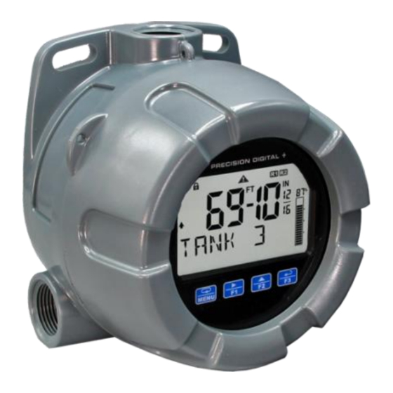
PD6907 Loop-Powered Feet & Inches Meter
Instruction Manual
•
Loop-Powered Field-Mount Feet & Inches Meters
•
4-20 mA Input Displayed with ±0.02% of Full-Scale Accuracy
•
1.5 Volt Drop (4.7 Volt Drop with Backlight)
•
0.7" (17.0 mm) 5 Digits 7-Segment, FT-IN & Fractions Top Display
•
0.4" (10.2 mm) 8 Alphanumeric 14-Segment Characters Bottom Display
•
Displays Level in Feet & Inches up to 999 Feet, 11 & 15/16 Inches
•
Display Input in Two Different Scales Simultaneously - Great for Level
•
20-Segment Bargraph Standard
•
Display Mountable at 0°, 90°, 180°, & 270°
•
CapTouch Through-Window Button Programming with Normal and Delayed Modes
•
Loop-Powered Backlight with Red Backlight for Alarm Conditions
•
(2) Open Collector Outputs Standard; Assignable to Pulse, Alarm, Timer, or Stopwatch
•
(2) Optional Loop-Powered Solid-State Relays; Assignable to Alarm, Control, Timer, or Stopwatch
•
Stopwatch & Timer Functions to Drive Relays & Open Collectors
•
Optional Isolated 4-20 mA Analog Output
•
Relay Pump Alternation Based on Level and Runtime
•
Display Relay Runtime & Cycle Count via Relay Info Menu
•
Round Horizontal Tank Function; Just Enter Diameter & Length
•
32-Point Linearization
•
Free PC-Based MeterView XL USB Programming Software
•
HART® Protocol Transparent
•
Enable and Disable Backlight from Menu
•
Operating Temperature Range: -40 to 75°C (-40 to 167°F)
•
Conformal Coated PCBs for Dust & Humidity Protection
•
Password Protection
•
Flange for Wall or Pipe Mounting; Loop for Stainless Steel Tag; Holes for Tamper-Proof Seal
•
Plastic NEMA 4X, IP66 Enclosure
•
Three 3/4" NPT Threaded Conduit Openings (Two Plugs Included)
•
3-Year Warranty
PRECISION DIGITAL CORPORATION
233 South Street • Hopkinton MA 01748 USA
Tel (800) 343-1001 • Fax (508) 655-8990
www.predig.com
MeterView XL
USB Install
Advertisement
Table of Contents
Troubleshooting

Subscribe to Our Youtube Channel
Related Manuals for Precision Digital Corporation PD6900-GP


Summary of Contents for Precision Digital Corporation PD6900-GP
- Page 1 Flange for Wall or Pipe Mounting; Loop for Stainless Steel Tag; Holes for Tamper-Proof Seal • Plastic NEMA 4X, IP66 Enclosure • Three 3/4" NPT Threaded Conduit Openings (Two Plugs Included) • 3-Year Warranty PRECISION DIGITAL CORPORATION 233 South Street • Hopkinton MA 01748 USA Tel (800) 343-1001 • Fax (508) 655-8990 www.predig.com...
- Page 2 PD6907 Loop-Powered Feet & Inches Meter Instruction Manual The Complete PD6900 Series Plastic Enclosures - General Purpose PD6907-GP-PL PD6908-GP-PL PD6928-GP-PL PD6938-GP-PL 4-20 mA Input 4-20 mA Input 4-20 mA Input Pulse Input Feet & Inches Meter Process Meter Flow Rate/Totalizer Flow Rate/Totalizer Aluminum Enclosures - Hazardous Area Approved PD6907-HA-AL...
-
Page 3: Table Of Contents
PD6907 Loop-Powered Feet & Inches Meter Instruction Manual Table of Contents Introduction ......................6 Key Features ......................7 Ordering Information ..................11 Accessories ....................11 Specifications..................... 13 Display ......................13 General ......................13 Enclosure ....................... 14 Input ........................ 14 Common Open Collector & Relay Specifications ........14 Open Collector Outputs ................ - Page 4 PD6907 Loop-Powered Feet & Inches Meter Instruction Manual Programming the Outputs (OUTPUT) ............36 Open Collector Outputs (OPEN COLLECTR) ..........37 Solid-State Relay Outputs (RELAY) ............42 Isolated 4-20 mA Output (4-20 mA) ............48 Output Manual Control (CONTROL) ............. 48 Advanced Features Menu (ADVANCE) ............
- Page 5 PD6907 Loop-Powered Feet & Inches Meter Instruction Manual Table of Figures Figure 1. Enclosure Dimensions – Front View ............ 17 Figure 2. Enclosure Dimensions – Side View ............. 17 Figure 3. Enclosure Dimensions – Top View ............17 Figure 4. Connector Labeling for PD6907-GP-PL-LNN........19 Figure 5.
-
Page 6: Introduction
LCD that can be read in bright sunlight Limited Warranty or dimly lit areas. Precision Digital Corporation warrants this Free, PC-based, MeterView XL software that product against defects in material or connects to the meter via a micro USB cable is workmanship for the specified period under available for programming and setup of the meters. -
Page 7: Key Features
PD6907 Loop-Powered Feet & Inches Meter Instruction Manual Key Features 2X More Informative Display CapTouch Through-Window The PD6907 display offers a 50% larger display area Buttons and is twice more informative than previous The PD6907 is equipped with four capacitive sensors generations of loop-powered meters. - Page 8 PD6907 Loop-Powered Feet & Inches Meter Instruction Manual Feet & Inches Display with Multiple Outputs • Two open collector outputs (standard) Bargraph • Two solid-state relays (optional) Designed for users that prefer to read level in feet and • inches instead of a decimal format, the PD6907 can One 4-20 mA output (optional) display level up to 999FT 11IN &...
- Page 9 PD6907 Loop-Powered Feet & Inches Meter Instruction Manual Modern and Practical Enclosure The PD6907 NEMA 4X, IP66 plastic enclosure SS Tag Attaching Loop provides serious protection from the elements, high The enclosure is also equipped with a loop at the top impact, corrosion, dust, etc.
- Page 10 PD6907 Loop-Powered Feet & Inches Meter Instruction Manual Pump Alternation Input Signal Conditioning The PD6907 can be used as a pump controller to The Function menu is used to select the input signal alternate two pumps and indicate high and low alarm conditioner applied to the input: linear or round conditions.
-
Page 11: Ordering Information
PD6907 Loop-Powered Feet & Inches Meter Instruction Manual Ordering Information General Purpose Instruments VantageView+ PD6907 • Feet & Inches – Plastic Enclosure Model Description PD6907-GP-PL-LNN Loop-Powered Field-Mount Feet & Inches Meter, No Options PD6907-GP-PL-L2N Loop-Powered Field-Mount Feet & Inches Meter, Two Solid-State Relays PD6907-GP-PL-L3N Loop-Powered Field-Mount Feet &... - Page 12 PD6907 Loop-Powered Feet & Inches Meter Instruction Manual PDA1024-01 24 VDC Power Supply PD9501 Multi-Function Calibrator The PDA1024-01 is a DIN rail mounted 1.5 A, 24 VDC power supply that can be used to power the 4-20 mA transmitter. This PD9501 Multi-Function Calibrator has a variety PDA6846 2"...
-
Page 13: Specifications
PD6907 Loop-Powered Feet & Inches Meter Instruction Manual Specifications General Except where noted all specifications apply to operation at +25°C. Programming Four CapTouch through-window buttons Method when cover is installed. The CapTouch Display buttons can be used with the cover removed. Free PC-based USB MeterView XL Display Dual-line LCD with backlight. -
Page 14: Enclosure
PD6907 Loop-Powered Feet & Inches Meter Instruction Manual Enclosure Common Open Collector & Relay Specifications Material Polycarbonate plastic with UV stabilizer Gasket Buna-N Number Two open collectors & two relays Rating NEMA 4X, IP66 plastic, UL 94V-0 Color Gray High or Low User programmable for high or low alarm Window Clear polycarbonate with UV stabilizer... -
Page 15: Solid-State Relays
PD6907 Loop-Powered Feet & Inches Meter Instruction Manual Solid-State Relays On-Board Digital Input Rating 250 VAC/VDC @ 0.5 A resistive Function Remote acknowledge/reset relays, reset 38 VA; 250 VAC; 0.3 A pilot duty max/min values, etc. See User section of (inductive) Display Functions &... -
Page 16: Compliance Information
PD6907 Loop-Powered Feet & Inches Meter Instruction Manual Compliance Information EU Declaration of Conformity Electromagnetic Compatibility For shipments to the EU and UK, a Declaration of EMC Emissions • Conformity was printed and included with the product. CFR 47 FCC Part 15 Subpart B Class A emissions requirements (USA) For reference, a Declaration of Conformity is also •... -
Page 17: Installation
PD6907 Loop-Powered Feet & Inches Meter Instruction Manual Installation To access the connectors, remove the enclosure cover and unclip the display module by pulling it from the enclosure. The display module may be disconnected from the options module to facilitate wiring to the options module. -
Page 18: Connections
PD6907 Loop-Powered Feet & Inches Meter Instruction Manual Connections To access the connectors, remove the enclosure cover and unclip the display module by pulling it from the enclosure. Signal, backlight, open collector, and digital input connections are made to removable connectors on the display module. -
Page 19: Connectors Labeling
PD6907 Loop-Powered Feet & Inches Meter Instruction Manual Connectors Labeling The following graphics show the locations of the connectors for each available configuration. – – Open Collector Connection Outputs Ribbon Cable Connector Digital Backlight Input + Signal – – – + BL mA CapTouch On/Off... -
Page 20: Figure 6. Connector Labeling For Pd6907-Gp-Pl-L3N
PD6907 Loop-Powered Feet & Inches Meter Instruction Manual Options Board – – 4-20 mA Open Collector Output – Connection Outputs Ribbon Cable Connector Digital Backlight Input + Signal – – – + BL mA CapTouch On/Off Switch Figure 6. Connector Labeling for PD6907-GP-PL-L3N Options Board –... -
Page 21: Wiring Diagrams
PD6907 Loop-Powered Feet & Inches Meter Instruction Manual Wiring Diagrams Digital Input Connections A digital input is standard on the meter. This digital input is connected with a normally open contact Current Loop (4-20 mA) Connections across DI+ and DI-, or with an active low signal Signal connections are made to a three-terminal applied to DI+ and DI-. -
Page 22: Open Collector Output Connections
PD6907 Loop-Powered Feet & Inches Meter Instruction Manual Open Collector Output Connections Remote Operation of Meter Open collector output 1 and 2 connections are made The meter is equipped with a digital input that can be to terminals labeled OC1 and OC2 on Figure 4, page programmed to perform various functions. -
Page 23: Setup And Programming
PD6907 Loop-Powered Feet & Inches Meter Instruction Manual Setup and Programming CapTouch Buttons Delay The CapTouch have two modes of operation: Normal and Delayed. Use the Delayed mode to prevent The meter is factory calibrated prior to shipment to display accidental trigger of the buttons. -
Page 24: Meterview Xl Programming Software
PD6907 Loop-Powered Feet & Inches Meter Instruction Manual MeterView XL Programming Software The fastest and easiest way to program the meter is To download the latest MeterView XL programming using the free Meterview XL programming software. software and manual, visit predig.com/meterviewxl. This software greatly simplifies the programming process and allows the user to save configuration files for later use. -
Page 25: Captouch Buttons And Status Indicators
PD6907 Loop-Powered Feet & Inches Meter Instruction Manual CapTouch Buttons and Status Indicators Indicators Buttons Indicator State Description Button Description Steady Process trend arrows Menu Flashing Alarm Indicator Right Arrow/F1 Steady Password protected Steady Solid-state relay 1 Up Arrow/F2 Steady Solid-state relay 2 CapTouch buttons Enter/F3... -
Page 26: Display Functions & Messages
PD6907 Loop-Powered Feet & Inches Meter Instruction Manual Display Functions & Messages Display Functions & Messages Parameter Action/Setting Description The meter displays various functions and messages during setup, programming, and operation. The following table DISABLE Disable the relay shows the main menu functions and messages in the order ALARM Program relay for alarm they appear in the menu. - Page 27 PD6907 Loop-Powered Feet & Inches Meter Instruction Manual Display Functions & Messages Display Functions & Messages Parameter Action/Setting Description Parameter Action/Setting Description DISABLE RLY2 Disable low-height cutoff Start/stop relay 2 timer ENABLE START Enable low-height cutoff Start the selected timer output FILTER STOP Set noise filter value...
- Page 28 PD6907 Loop-Powered Feet & Inches Meter Instruction Manual Display Functions & Messages Display Functions & Messages Parameter Action/Setting Description Parameter Action/Setting Description PV 2 TIMR OC2 Enable the meter to scale a Display open collector 2 timer second PV based on the same TIMER R1 Display relay 1 timer 4-20 mA input...
-
Page 29: Main Menu
PD6907 Loop-Powered Feet & Inches Meter Instruction Manual Main Menu The main menu consists of all the meter’s programmable functions: Input, Output, Advanced, and Display. • Press Menu button to enter Programming Mode then press the Right-Arrow button to move forward through the menu and the Up-Arrow button to move back. -
Page 30: Setting Numeric Values
PD6907 Loop-Powered Feet & Inches Meter Instruction Manual Setting Numeric Values The numeric values are set using the Right and Up-Arrow buttons. Press Right-Arrow to select next digit and Up-Arrow to increment digit value. The selected digit will flash. Press and hold Up-Arrow to auto-increment the display value. If you have made a mistake or would like to enter a new value, select the left-most digit, and press and hold the Right-Arrow button until all digits reset to zero. -
Page 31: Scaling The 4-20 Ma Input (Input)
PD6907 Loop-Powered Feet & Inches Meter Instruction Manual Scaling the 4-20 mA Input (INPUT) It is very important to read the following information before proceeding to program the meter: • The meter is factory calibrated prior to shipment to display 0.00 to 100.00 FT, which corresponds to the 4-20 mA input. -
Page 32: Available Unit Classes And Units
PD6907 Loop-Powered Feet & Inches Meter Instruction Manual Available Unit Classes and Units Pressure Units (PRESSURE) Pounds per square inch The process variable (PV) can be scaled in several different height units. No matter the scaling units, the InHg Inches of mercury scaled value will be converted to feet &... -
Page 33: Setting Custom Units (Custom)
PD6907 Loop-Powered Feet & Inches Meter Instruction Manual Setting Custom Units (CUSTOM) When the desired unit class or unit of measure within a class for PV2 is not available, a custom unit may be programmed. Select the CUSTOM menu (or CUSTOM unit within a unit class) to enter a custom unit name. Text values are set using the Right and Up-Arrow buttons. -
Page 34: Setting The Display Features (Display)
PD6907 Loop-Powered Feet & Inches Meter Instruction Manual Setting the Display Features (DISPLAY) The meter’s display functions may be programmed using the Display menu. This menu consists of the following submenus: Units, Decimal Point, Comma, Bargraph, Top, and Bottom. Changing the Engineering Units (UNITS) The UNITS menu is used to change how fractional inches are represented. -
Page 35: Enabling Or Disabling Commas On The Bottom Display (Comma)
PD6907 Loop-Powered Feet & Inches Meter Instruction Manual Enabling or Disabling Commas on the Configuring the Display Bottom Display (COMMA) (BOTTOM) The bottom display is set to show a comma The bottom display line (BOTTOM) can be separating the thousands and millions place by programmed to display different values. -
Page 36: Programming The Bargraph (Bargraph)
PD6907 Loop-Powered Feet & Inches Meter Instruction Manual Programming the Bargraph (BARGRAPH) The meter comes equipped with a bargraph display for applications where a visual representation of the process variable’s percentage of full scale is desirable. This feature can be enabled or disabled using the Bargraph menu (BARGRAPH). -
Page 37: Open Collector Outputs (Open Collectr)
PD6907 Loop-Powered Feet & Inches Meter Instruction Manual Open Collector Outputs (OPEN COLLECTR) The meter is equipped with two NPN open collector outputs as a standard feature that may be set up for pulse outputs, alarms, timed pulses, or disabled. Pulse outputs can be set to transmit the PV value (PV1 or PV2 if meter is in dual-scale mode). - Page 38 PD6907 Loop-Powered Feet & Inches Meter Instruction Manual Pulse Output (PULSE) The pulse outputs may be programmed to generate a scaled frequency based on the PV and a programmable factor. The factor determines the number of pulses per second generated per unit of measure. For example, if the meter display shows 100 gallons and the factor is set to 2, the number of pulses generated per second would be 200.
- Page 39 PD6907 Loop-Powered Feet & Inches Meter Instruction Manual Alarm (ALARM) Alarm outputs may be assigned to the PV or the digital input. When assigned to the PV, the alarm may be set as either a high alarm or a low alarm. Alarm actions (AUTO, AUTO. M AN, LATCH, L-CLEAR) determine how and when the alarm should be reset.
- Page 40 PD6907 Loop-Powered Feet & Inches Meter Instruction Manual Flashing Red Alarm (RED) The last two lines in the preceding menu flow chart show how to program the display to turn red, flash, and display a message when an alarm occurs. Timer (TIMER) The timer output may be set to generate the timed pulse only once (ONESHOT) or continuously (CONT).
- Page 41 PD6907 Loop-Powered Feet & Inches Meter Instruction Manual Stopwatch (STPWATCH) The stopwatch function may be used to manually run and control a process for a specific time interval up to 99 hrs., 59 min, and 59 seconds. The stopwatch function may be assigned to any open collector. There are three settings needed to use the function effectively.
-
Page 42: Solid-State Relay Outputs (Relay)
PD6907 Loop-Powered Feet & Inches Meter Instruction Manual Solid-State Relay Outputs (RELAY) The meter can be optionally equipped with two solid-state relays that may be set up for alarms, timer, stopwatch, or pump control. Alternatively, they may be disabled. Alarms are available based on the PV value or the digital input. The alarm status will show on the display even if the output is not wired. - Page 43 PD6907 Loop-Powered Feet & Inches Meter Instruction Manual Alarm (ALARM) Alarm outputs may be assigned to the PV or the digital input. When assigned to the PV, the alarm may be set as either a high alarm or a low alarm. Alarm actions (AUTO, AUTO. M AN, LATCH, L-CLEAR) determine how and when the alarm should be reset.
- Page 44 PD6907 Loop-Powered Feet & Inches Meter Instruction Manual Pump Control (PUMPCTRL) The pump control output is used in situations where the relays are used to control pumps. There are two options available for controlling pumps: on-off (ON-OFF) and pump alternation (ALTERN). ON-OFF will turn the relay on at a programmed on point and off at a programmed off point.
- Page 45 PD6907 Loop-Powered Feet & Inches Meter Instruction Manual Pump Alternation (ALTERN) Pump alternation sets the two relays to alternate every time the first on point (ON 1) is reached. The active relay will turn off once the first off point (OFF 1) is reached. If the PV reaches the second on point (ON 2), the other relay will also turn on.
- Page 46 PD6907 Loop-Powered Feet & Inches Meter Instruction Manual Pump Control with Alternation & Alarm Example The following is a typical application where the relays and open collectors are used for pump alternation and high and low level alarm. Pump and Alarm On & Off Point Programming Relay On Point Off Point...
- Page 47 PD6907 Loop-Powered Feet & Inches Meter Instruction Manual Timer (TIMER) The timer output may be set to generate the timed pulse only once (ONESHOT) or continuously (CONT). The timer output produces a constant width pulse at a constant frequency, if set as continuous timer. Program the Off Delay (OFF.
-
Page 48: Isolated 4-20 Ma Output (4-20 Ma)
PD6907 Loop-Powered Feet & Inches Meter Instruction Manual Runtime & Cycle Count (INFO) The relay information menu shows runtime and cycle count for each relay. These values may be cleared at any time by selecting the Clear option (CLEAR?). Isolated 4-20 mA Output (4-20 mA) The 4-20 mA menu is used to scale the isolated 4-20 mA output based on display values. -
Page 49: Advanced Features Menu (Advance)
PD6907 Loop-Powered Feet & Inches Meter Instruction Manual Advanced Features Menu (ADVANCE) To simplify the setup process, functions not needed for most applications are located in the Advanced Features menu. The options under advanced features include advanced PV setup, cutoff, filter, password, function key programming, and system settings. -
Page 50: Advanced Process Variable Setup (Adv Pv)
PD6907 Loop-Powered Feet & Inches Meter Instruction Manual Advanced Process Variable Setup (ADV PV) The Advanced PV Setup menu contains options to apply input signal conditioning functions to the input and to scale/calibrate the input signal. Input Signal Conditioning Functions (FUNCTN) The Function menu is used to select the input signal conditioner applied to the input: linear, square root, programmable exponent, or round horizontal tank volume calculation. - Page 51 PD6907 Loop-Powered Feet & Inches Meter Instruction Manual Using MeterView XL MeterView XL makes programming the input signal conditioning functions quick and easy. Go to the input/scale menu and select the desired function from the drop down menu in the “scale input” section.
- Page 52 PD6907 Loop-Powered Feet & Inches Meter Instruction Manual Multi-Point Linearization (LINEAR) MeterView XL showing the Up to 32 linearization points can be selected for PV1 and linear points setup feature. Up PV2 under the LINEAR function. Multi-point linearization to 32 points can be selected can be used to linearize the input so the meter can display for PV1 and PV2.
- Page 53 PD6907 Loop-Powered Feet & Inches Meter Instruction Manual Round Horizontal Tank Linearization (RH TANK) This function automatically calculates the volume in a round horizontal tank with flat ends. It is only available for PV2 while the meter is in dual-scale mode. Select units (feet, inches, or cm) for the tank dimensions.
- Page 54 PD6907 Loop-Powered Feet & Inches Meter Instruction Manual Advanced Scaling and Calibration (SCALE. C AL) This menu offers options to scale or calibrate the meter. Scaling the Input (SCALE) The scale menu in the Advanced menu is the same as the scale menu in the Input menu. See Scaling the 4-20 mA Input (INPUT) on page 31 for details about scaling the meter.
-
Page 55: Low-Height Cutoff (Cutoff)
PD6907 Loop-Powered Feet & Inches Meter Instruction Manual Low-Height Cutoff (CUTOFF) The low-height cutoff feature allows the meter to be programmed so that the often-unsteady output from a differential pressure transmitter at low flow rates always displays zero on the meter. The cutoff value may be programmed from 0.1 to 99999. -
Page 56: Programmable Function Keys User Menu (User)
PD6907 Loop-Powered Feet & Inches Meter Instruction Manual Programmable Function Keys User Menu (USER) The User menu allows the user to assign the CapTouch buttons function keys F1, F2, and F3, and the digital input (located on the input signal connector) to access some of the menus or to activate certain functions immediately (e.g. reset max &... -
Page 57: Tare (Tare)
PD6907 Loop-Powered Feet & Inches Meter Instruction Manual Function Keys & Digital Input Display Description Available Settings START Start the stopwatch Refer to the following table for descriptions of each STOP Pause/Stop the stopwatch available function key or digital input setting. STR-STP Start or stop the stopwatch TARE. -
Page 58: Changing System Settings (System)
PD6907 Loop-Powered Feet & Inches Meter Instruction Manual Changing System Settings (SYSTEM) Enabling the Dual-Scale Feature (PV2) The System menu contains the following menus: Analog Output Calibration, Restore Factory Defaults, Dual-Scale (PV2), Backlight, CapTouch Buttons Operation Mode, Information, and Internal Calibration. Note: The Analog Output Calibration menu is available only if the option is installed. - Page 59 PD6907 Loop-Powered Feet & Inches Meter Instruction Manual Enabling or Disabling the Calibrating the Internal mA Backlight (BACKLITE) Reference (ICAL) The backlight may be enabled or disabled using the The meter is factory calibrated prior to shipment to display System - Backlight menu. The backlight is enabled by 0.00 to 100.00, which corresponds to the 4-20 mA input.
-
Page 60: Meter Operation
PD6907 Loop-Powered Feet & Inches Meter Instruction Manual Meter Operation CapTouch Buttons The meter is equipped with four CapTouch through- The PD6907 is equipped with four capacitive sensors window buttons. These buttons allow meter operation that operate as through-window buttons so that it can without removing the cover and exposing the be programmed and operated without removing the electronics in a harsh operating area. -
Page 61: Function Keys Operation
PD6907 Loop-Powered Feet & Inches Meter Instruction Manual Function Keys Operation Runtime & Cycle Count (INFO) During operation, the programmable function keys The relay information menu shows runtime and cycle operate according to the way they have been count for each relay. These values may be cleared at programmed in the Advanced Features –... -
Page 62: Troubleshooting
PD6907 Loop-Powered Feet & Inches Meter Instruction Manual Troubleshooting Determining Software Version This product is a highly sophisticated instrument with To determine the software (firmware) version of a an extensive list of features and capabilities. If the meter: CapTouch buttons are used to program the meter, it Press the Menu button to enter can be a difficult task to keep everything straight. -
Page 63: Factory Default Settings
PD6907 Loop-Powered Feet & Inches Meter Instruction Manual Factory Default Settings Parameter Display Default Setting The following table shows the factory setting for most Pump Control Menu of the programmable parameters on the meter. Pump Ctrl On 70.00 Parameter Display Default Setting Pump Ctrl Off 60.00... -
Page 64: Troubleshooting Tips
PD6907 Loop-Powered Feet & Inches Meter Instruction Manual Troubleshooting Tips Certain sequences of events can cause unexpected results. To solve these issues, it is best to start fresh from factory defau lts and use the manual as a step by step programming guide, rather than a random approach to programming. To reset the meter to fac tory defaults, see Factory Default Settings on page 63. - Page 66 Email: sales@predig.com Place Orders Email: orders@predig.com For the latest version of this manual please visit www.predig.com PRECISION DIGITAL CORPORATION 233 South Street • Hopkinton MA 01748 USA Tel (800) 343-1001 • Fax (508) 655-8990 www.predig.com LIM6907GP_B SFT125 Ver 1.000 & up...
Need help?
Do you have a question about the PD6900-GP and is the answer not in the manual?
Questions and answers