Table of Contents
Advertisement
D I G I T A L P A N E L M E T E R S
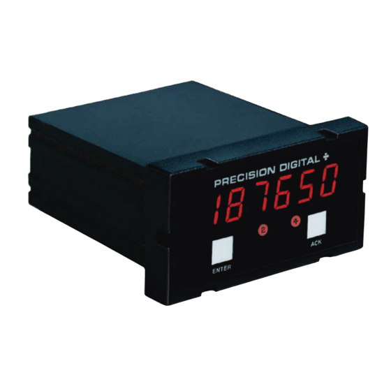
Model PD690 Universal Process Meter
Instruction Manual
®
• Easy Single Button Scaling (SBS)
• 4-20 mA, 0-5 V, or 0-10 V Field Selectable Inputs
• 24 V Transmitter Power Supply Standard
• Scale Without a Calibrator
• Calibrate with a Signal Source
• Steady, Accurate Display to ± 199,990
• 11-Point Linearization for Non-Linear Inputs
• Square Root Extraction with Low-Flow Cutoff
• 4
/
Digit + Extra Zero
1
2
• NEMA 4X, IP65 Front Panel
• 2 or 4 Relays + 4-20 mA Output Options
• 115 VAC, 230 VAC, or 24 VDC Power Options
• Lockout Feature
• Non-Volatile Memory, No Battery Needed
PRECISION DIGITAL CORPORATION
19 Strathmore Road • Natick MA 01760 USA
www.predig.com
•
Tel 800-610-5239
Fax 508-655-8990
Advertisement
Table of Contents

Subscribe to Our Youtube Channel
Related Manuals for Precision Digital Corporation PD690 Series


Summary of Contents for Precision Digital Corporation PD690 Series
- Page 1 • 2 or 4 Relays + 4-20 mA Output Options • 115 VAC, 230 VAC, or 24 VDC Power Options • Lockout Feature • Non-Volatile Memory, No Battery Needed PRECISION DIGITAL CORPORATION 19 Strathmore Road • Natick MA 01760 USA www.predig.com •...
-
Page 2: Table Of Contents
Model PD690 Universal Process Meter Instruction Manual INTRODUCTION ..................4 Typical Applications ................4 Ordering Information................4 Safety Notice ..................5 Specifications ..................6 Basic Meter..................6 Options ....................7 Display Messages and Functions............9 SETUP AND PROGRAMMING ............10 Power, Signal, External Functions & Options Connections..10 Overview ....................11 Wiring Instructions................11 AC Powered Units (Power, Signal, External Functions) ....12 DC Powered Units (Power, Signal, External Functions) ....14... - Page 3 Model PD690 Universal Process Meter Instruction Manual Select Square Root Extraction (L or S) ........24 Program Low-Flow Cutoff ([vtoff)..........24 Round Horizontal Tank Calibration Table ........25 Isolated 4-20 mA Output Option Programming (ovtpvt)..26 Setting 4 mA Output Value............26 Setting 20 mA Output Value............26 Programming Confirmation............26 Alarm Programming ................27 Overview ..................27...
-
Page 4: Introduction
Model PD690 Universal Process Meter Instruction Manual INTRODUCTION This meter is a high performance, easy to use, industrial-grade micro- processor-based digital process meter. It accepts all the standard process signals: 4-20 mA, 1-5V, 0-5V and 0-10V and displays these sig- nals in engineering units on a 4 digit display. -
Page 5: Safety Notice
Model PD690 Universal Process Meter Instruction Manual Safety Notice CAUTION: Read complete instructions WARNING: Risk of prior to installation and operation of electric shock. the Meter. Observe all safety regulations. Electrical wiring should be performed in accordance with all applicable national, state and local codes to prevent damage to the Meter and ensure personnel safety. -
Page 6: Specifications
Model PD690 Universal Process Meter Instruction Manual SPECIFICATIONS Except where noted all specifications apply to operation at +25ºC Basic Meter INPUTS Field selectable: 4-20 mA, 0-20 mA, 0-5 V, 1-5 V, 0-10 V. DISPLAY Bright, large, 0.56" (14.2mm) high efficiency red LEDs. -
Page 7: Options
Model PD690 Universal Process Meter Instruction Manual 11-POINT Input Range Minimum Span LINEARIZATION Between Inputs 4-20 mA (1.6 mA / (Number of points –1)) 0-5 V (0.16 V / (Number of points -1)) 0-10 V (0.32 V / (Number of points -1)) e.g. - Page 8 Model PD690 Universal Process Meter Instruction Manual RESET User Select: 1. Automatically when input passes reset point. 2. Automatically + Manually (via user supplied switch or front panel ACK button). Manual reset resets all manually resetable relays. DEADBAND 0-100% of full scale, user selectable. HIGH OR LOW User may program any alarm for a high or low ALARM...
-
Page 9: Display Messages And Functions
Model PD690 Universal Process Meter Instruction Manual Display Messages and Functions The following table describes the various messages displayed by the meter during programming and operation: Display Parameter Description/Comments Select External Set meter for calibration using E-[AL Calibration an external calibration source. Select Internal Set meter for calibration (scaling) I-[AL... -
Page 10: Setup And Programming
Model PD690 Universal Process Meter Instruction Manual SETUP AND PROGRAMMING Power, Signal, External Functions & Options Connections Disconnect power to the meter before making any connections. Do not connect power or earth ground to any unused or CM terminals. Observe polarity for DC powered Meters. Applying voltage with reverse polarity may damage the instrument. -
Page 11: Overview
Model PD690 Universal Process Meter Instruction Manual Overview The following field wiring connections are made to removable screw terminal blocks supplied with the meter: Power, Signal Input, Acknowledge and Hold Options: Relays & 4-20 mA Output AK H Figure 1: Rear View of Meter (Connectors) Label Main Board (Lower) Wire Size... -
Page 12: Ac Powered Units (Power, Signal, External Functions)
Model PD690 Universal Process Meter Instruction Manual AC Powered Meters (Power, Signal, External Functions) 4-20 mA Transmitter – Signal Input Lockout Selection Array Jumper 3 2 1 L L P+ P- S- S+ C H A O L C M D K Figure 2: Transmitter Powered from Meter Loop 4-20 mA... - Page 13 Model PD690 Universal Process Meter Instruction Manual AC Powered Meters (Continued) 3-Wire Transducer Signal Signal Input Lockout Selection Jumper Array See page 20 3 2 1 for Input Signal selection table L L P+ P- S- S+ C H A O L C M D K Figure 4: Three-Wire Transducer Powered from Meter...
-
Page 14: Dc Powered Units (Power, Signal, External Functions)
Model PD690 Universal Process Meter Instruction Manual DC Powered Meters (Power, Signal, External Functions) 24 VDC 4-20 mA Power Supply Transmitter – + – Signal Input Selection Lockout Array Jumper 3 2 1 S- S+ C V- V+ *For signal/power isolation seperate power supplies are required. -
Page 15: Relays & 4-20 Ma Output
Model PD690 Universal Process Meter Instruction Manual Relays & 4-20 mA Output Depending on the model number, the Options Board may contain two or four relays and an Isolated 4-20 mA Transmitter Output. Relay con- nections are made to removable screw terminal connectors located at J2 and J3 on the Options Board. -
Page 16: 4-20 Ma Output
Model PD690 Universal Process Meter Instruction Manual 4-20 mA Output The 4-20 mA output from the meter can either be powered from the meter’s internal transmitter power supply, (if it is not being used to power the input loop), or by an external power supply as the follow- ing diagrams illustrate: Signal Input... -
Page 17: Programming
Model PD690 Universal Process Meter Instruction Manual Programming Overview The meter is programmed using the ENTER button and three jumper arrays. The ENTER button controls the meter’s S ingle B utton S caling (SBS) feature that allows the meter to be completely programmed using just one button. -
Page 18: Two-Point External Calibration Flow Chart
Model PD690 Universal Process Meter Instruction Manual Figure 13: Two-point External Calibration Flow Chart Push ENTER Apply input 1 signal (e.g. 4 mA) Push ENTER entire flashing Push ENTER display OK? Wait for input 2 been digit to flash calibrated yet? Wait for digit Calibration... -
Page 19: Five Basic Digit/Display-Setting Instructions
Model PD690 Universal Process Meter Instruction Manual Five Basic Digit/Display-setting Instructions Rather than repeat the S ingle B utton S caling (SBS ) technique for every function it is used in, it will be detailed here and the user can refer to it when necessary. -
Page 20: Select Input Signal
Model PD690 Universal Process Meter Instruction Manual Select Input Signal The meter can be programmed to accept current or voltage input using the Signal Input Selection Array. This jumper array is located at the rear of the instrument, next to the screw terminal block. Remove jumper J3 (if installed) to disable Lockout feature. -
Page 21: Select Calibration Method
Model PD690 Universal Process Meter Instruction Manual Select Calibration Method The meter may be calibrated using an external signal source such as a calibrator (E-[AL), or scaled using the internal source (I-[AL). With I-[AL, a 4-20 mA input can be scaled for any display range without applying a signal. -
Page 22: General Calibration/Scaling Instructions
Model PD690 Universal Process Meter Instruction Manual General Calibration/Scaling Instructions Calibration is performed from the front panel using the ENTER but- ton. It does not require any tools or disassembly of the meter. A calibrated signal source is required if external calibration (E-[AL) is selected. -
Page 23: Calibrate Using An External Calibrator (E
Model PD690 Universal Process Meter Instruction Manual Calibrate Using an External Calibrator (E-[al) If E-[AL (External Calibration) was selected above in Select Calibration Method, the meter must be calibrated with an external calibrator. Desired values can be programmed using the Five Basic Digit/Display- setting Instructions described on page 19. -
Page 24: Select Square Root Extraction (L Or S)
Model PD690 Universal Process Meter Instruction Manual Select Square Root Extraction (L or S) With the square root extraction function activated, the meter takes the square root of the input signal (the output from a differential pressure transmitter) and displays flow rate. The square root extraction feature is calibrated using the same S ingle B utton S caling technique that is used for two-point linear calibration. -
Page 25: Round Horizontal Tank Calibration Table
Model PD690 Universal Process Meter Instruction Manual Round Horizontal Tank Calibration Table The following tables can be used to calibrate the meter for displaying volume in a round horizontal tank. The right-most column in each table gives an example of actual calibration points for a 500-gallon tank. -
Page 26: Isolated 4-20 Ma Output Option Programming (Ovtpvt)
Model PD690 Universal Process Meter Instruction Manual Isolated 4-20 mA Transmitter Output Programming (ovtpvt) The Isolated 4-20 mA Transmitter Output option can be programmed without a calibrator. This option can be calibrated so that a 4 mA out- put is produced for any number displayed by the meter. The 20 mA output may be programmed to correspond to any number that is at least 501 counts greater or smaller than the number corresponding to 4 mA. -
Page 27: Alarm Programming
Model PD690 Universal Process Meter Instruction Manual Alarm Programming Overview The meter is equipped with four alarm points as a standard feature. Each alarm may be programmed for either a high or low alarm and for 0-100% deadband. Front panel LEDs indicate alarm status. Options for two or four relays are available. -
Page 28: Programming Confirmation
Model PD690 Universal Process Meter Instruction Manual Programming Confirmation To verify that the alarm set and reset points have been programmed as desired, push ENTER, and push ENTER again when ALArS appears. Before the display stops flashing #1 set point value, push ENTER again to advance the display to #1 reset point. -
Page 29: Alarm Acknowledgment
Model PD690 Universal Process Meter Instruction Manual Alarm Acknowledgment The ACK button on the front panel resets the optional relays only and has no effect on the alarm status LEDs. Automatic & Manual Reset Programming There are two ways to reset the relays: 1. -
Page 30: Lockout Jumper
Model PD690 Universal Process Meter Instruction Manual Lockout Jumper Once the meter has been completely programmed, a lockout jumper can be installed to restrict further modification to the meter. This jumper is located at the rear of the instrument and is labeled J3. When ENTER is pushed with the lockout jumper in place, only ALArS and ovtPvt routines are displayed. -
Page 31: Low Voltage Dc Loads
Model PD690 Universal Process Meter Instruction Manual Low Voltage DC Loads Figure 16: Low Voltage DC Loads Use a diode with a reverse breakdown voltage two to three times the circuit voltage and forward current at least as large as the load cur- rent. -
Page 32: Option Card Installation
Model PD690 Universal Process Meter Instruction Manual OPTIONS CARD REMOVAL & INSTALLATION Meter options are installed at the factory. It is NOT necessary to remove the circuit boards from the case to disable the relays’ fail-safe operation. The fail-safe jumper is located on the Display Board, see Figure 14 on page 29. -
Page 33: Mounting Dimensions
Model PD690 Universal Process Meter Instruction Manual To re-install the meter in its case: 1. Fold the Options Board over the Main Board, grasp both boards so the Main Board is on the bottom and the two Boards are separated by about an inch. -
Page 34: Programmed Parameter Settings
Model PD690 Universal Process Meter Instruction Manual PROGRAMMED PARAMETER SETTINGS Use the following table to record how your meter is programmed: Input 4-20 mA 0-5 V 1-5 V 0-10 V Linear Square Root Extraction Number of Calibration Points Low-Flow Cutoff Value Calibration Point Values Input 1 set point display 1... -
Page 35: Other Precision Digital Products
Model PD690 Universal Process Meter Instruction Manual OTHER PRECISION DIGITAL PRODUCTS MODEL DESCRIPTION PD118 MINIMUX ® 8 Point Scanner PD141AFO VIGILANTE ® four Point Annunciator with First-Out PD202-253 Digital Pressure Gauges PD602 Dart Low-Cost 1/8 DIN Process Meter PD644 Javelin D High-Voltage DC Panel Meter PD650 2.3"... -
Page 36: How To Contact Precision Digital
• For Extended Warranty, Setup & Calibration Services please visit www.predig.com • For an online version of this instruction manual please visit www.predig.com PRECISION DIGITAL CORPORATION • 19 Strathmore Road Natick MA 01760 USA LIM690 Rev F • Tel 800-610-5239...
Need help?
Do you have a question about the PD690 Series and is the answer not in the manual?
Questions and answers