
Related Manuals for Perkins 1706EA-E93TA


Summary of Contents for Perkins 1706EA-E93TA
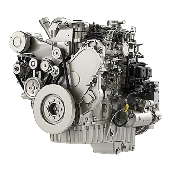
- Page 1 M0087475-06 (en-us) February 2022 Operation and Maintenance Manual 1706J-E93TA and 1706EA-E93TA Industrial Engines NGK (Engine) YGF (Engine) YGE (Engine)
- Page 2 If a tool, procedure, work method or operating technique that is not specifically recommended by Perkins is used, you must satisfy yourself that it is safe for you and for others. You should also ensure that you are authorized to perform this work, and that the product will not be damaged or become unsafe by the operation, lubrication, maintenance or repair procedures that you intend to use.
-
Page 3: Table Of Contents
M0087475-06 Table of Contents Table of Contents Cold Weather Operation ......... 68 Maintenance Section Foreword ............4 Refill Capacities..........70 Safety Section Maintenance Recommendations ....87 Safety Messages..........6 Maintenance Interval Schedule....... 90 Additional Messages ......... 7 Warranty Section General Hazard Information......8 Warranty Information........ -
Page 4: Foreword
State of arises regarding your engine, or this manual, please California to cause cancer, birth defects, consult with your Perkins dealer or your Perkins distributor for the latest available information. and other reproductive harm. WARNING – This product can... - Page 5 Perkins distributor offers various options regarding overhaul programs. If you experience a major engine failure, there are also numerous after failure overhaul options available. Consult with your Perkins dealer or your Perkins distributor for information regarding these options.
-
Page 6: Safety Section
Replace any safety message that is damaged or missing. If a safety message is attached to a part of the engine that is replaced, install a new safety message on the replacement part. Your Perkins distributor can provide new safety messages. Illustration 1... -
Page 7: Additional Messages
Loose adhesive will allow the messages to fall. Replace any message that is damaged, or missing. If a message is attached to a part that is replaced, install a message on the replacement part. Replacement labels may be obtained from Perkins distributors. -
Page 8: General Hazard Information
M0087475-06 Safety Section General Hazard Information Illustration 4 g06652206 Illustration 6 g06652233 Purge notice message Typical example This notice should be located next to the battery This message is on the top of the radiator near the disconnect switch. cooling system filler cap. Refer to Operation and Maintenance Manual for more information. - Page 9 M0087475-06 Safety Section General Hazard Information • Vent the engine exhaust to the outside when the • For initial start-up of a new engine or for starting engine is operated in an enclosed area. an engine that has been serviced, make provisions to stop the engine if an overspeed •...
- Page 10 M0087475-06 Safety Section General Hazard Information • When work is performed around an engine that is Do not remove any hydraulic components or parts until pressure has been relieved or personal injury operating, wear protective devices for ears to help may occur.
- Page 11 Perkins equipment and replacement parts comply practices. with applicable regulations and requirements where originally sold. Perkins recommends the use of only genuine Perkins replacement parts. Lines, Tubes, and Hoses Hexavalent chromium has occasionally been detected on exhaust and heat shield systems on Do not bend or strike high-pressure lines.
- Page 12 Asbestos Information Perkins equipment and replacement parts that are shipped from Perkins engine company limited are asbestos free. Perkins recommends the use of only genuine Perkins replacement parts. Use the following guidelines when you handle any replacement parts that contain asbestos or when you handle asbestos debris.
-
Page 13: Burn Prevention
M0087475-06 Safety Section Burn Prevention • Wash thoroughly after handling DEF. Always wear protective glasses when you work with batteries. Wash hands after touching batteries. The use of gloves is recommended. i06086863 Burn Prevention Engine and Aftertreatment System Do not touch any part of an operating engine or engine aftertreatment system. - Page 14 Personal injury, property damage, or engine damage could result. If the application involves the presence of combustible gases, consult your Perkins dealer and/ or your Perkins distributor for additional information about suitable protection devices. Remove all flammable combustible materials or conductive materials such as fuel, oil, and debris from the engine.
-
Page 15: Crushing Prevention And Cutting Prevention
Do not bend high-pressure lines. Do not strike high- pressure lines. Do not install any lines that are damaged. Leaks can cause fires. Consult your Perkins dealer or your Perkins distributor for replacement parts. Check lines, tubes, and hoses carefully. Do not use your bare hand to check for leaks. -
Page 16: Mounting And Dismounting
M0087475-06 Safety Section Mounting and Dismounting When objects are struck, wear protective glasses in order to avoid injury to the eyes. Chips or other debris may fly off objects when objects are struck. Before objects are struck, ensure that no one will be injured by flying debris. - Page 17 M0087475-06 Safety Section High Pressure Fuel Lines Illustration 15 g06263148 (1) High-pressure fuel manifold (rail) (3) High-pressure lines to injectors (2) Fuel transfer lines that are high pressure (4) High-pressure fuel pump The high-pressure fuel lines are the fuel lines that are Do not check the high-pressure fuel lines with the between the high-pressure fuel pump and the high- engine or the starting motor in operation.
-
Page 18: Before Starting Engine
M0087475-06 Safety Section Before Starting Engine • Do not operate the engine with a fuel leak. If there All protective guards and all protective covers must be installed if the engine must be started in order to is a leak, do not tighten the connection, to stop the perform service procedures. -
Page 19: Engine Stopping
M0087475-06 Safety Section Engine Stopping Grounding Practices Note: The engine may be equipped with a device for cold starting. If the engine will be operated in very cold conditions, then an extra cold starting aid may be required. Normally, the engine will be equipped with the correct type of starting aid for your region of operation. -
Page 20: Engine Electronics
Note: Many of the engine control systems and discharge. display modules that are available for Perkins Engines will work in unison with the Engine To ensure that the engine and the engine electrical Monitoring System. -
Page 21: Product Information Section
M0087475-06 Product Information Section Model Views Product Information Section Model Views i08769106 Model View Illustrations The following model views show typical features of the engine. Due to individual applications, your engine may appear different from the illustrations. Engine views Illustration 18 g06275201 View of the top of a typical engine (1) Oil pan... - Page 22 M0087475-06 Product Information Section Model View Illustrations Illustration 19 g06275205 View of the left side of a typical engine (5) Oil filler tube (7) Electronic Control module (ECM) (6) Fuel Injection pump (8) Starting motor...
- Page 23 M0087475-06 Product Information Section Model View Illustrations Illustration 20 g06275226 View of the left side of a typical engine (9) Secondary fuel filters (12) Crankcase ventilation filter (15) Oil dipstick (10) Primary fuel filter/ water separator (13) Crankcase breather (11) Fuel pump switch assembly (14) Flywheel housing...
- Page 24 M0087475-06 Product Information Section Model View Illustrations Illustration 21 g06275229 View of the front right side of a typical engine (16) Oil filter (17) Alternator Aftertreatment Systems...
- Page 25 M0087475-06 Product Information Section Model View Illustrations Clean Emission Module (CEM) Illustration 22 g06255135 Typical example (1) Diesel Particulate Filter (DPF) (3) Selective Catalytic Reduction (SCR) (5) Exhaust outlet connection (2) SCR mixing chamber system (6) Diesel Oxidation Catalyst (DOC) (4) Diesel Exhaust Fluid (DEF) injector (7) Exhaust intake connection...
- Page 26 M0087475-06 Product Information Section Model View Illustrations Pump Electronic Tank Unit (PETU) Illustration 24 g06766356 Typical example Illustration 23 g06420797 (A) CEM identification plate Typical example (1) DEF filler cap (2) DEF tank header (3) DEF pump electronics containing filter (4) DEF tank (5) DEF tank drain Note: The DEF heated lines are supplied loose.
- Page 27 M0087475-06 Product Information Section Model View Illustrations Illustration 26 g06764639 Typical example (C) Position of the SCR marking (D) Position of the DPF marking...
- Page 28 M0087475-06 Product Information Section Model View Illustrations Illustration 27 g06764644 Illustration 29 g06764652 Typical example Typical example (E) Position of the turbocharger marking (G) Position of the ECM marking Illustration 28 g06764647 Typical example (F) Position of the electronic unit injector marking...
- Page 29 M0087475-06 Product Information Section Model View Illustrations Illustration 30 g06772069 Typical example (H) Position of the fuel manifold (rail) marking...
- Page 30 Rotation (flywheel end) Counterclockwise Product Description Air-to-air aftercooled Separate circuit after cooling The Perkins 1706J-E93TA and 1706EA-E93TA High-Pressure Fuel System Industrial Engines have the following characteristics: • Four-stroke cycle Fuel system has a high-pressure fuel pump to create fuel pressure. The fuel under high-pressure is •...
- Page 31 Maintenance Manual, “Overhaul Considerations” topic (Maintenance Section). Aftermarket Products and Perkins Engines Perkins does not warrant the quality or performance of non-Perkins fluids and filters. When auxiliary devices, accessories, or consumables (filters, additives, catalysts) which are made by other manufacturers are used on Perkins products, the Perkins warranty is not affected simply because of such use.
-
Page 32: Product Identification Information
M0087475-06 Product Information Section Product Identification Information Product Identification Information i07200488 Plate Locations and Film Locations Illustration 33 g06251121 Typical example (1) Engine serial number plate location Viewed from the rear of the engine, the serial number plate is on the right side of the cylinder block below the turbocharger. - Page 33 The Clean Emission Module (CEM) identification plate contains the following information: part number, serial number, change level, and configuration ID code. This information may be needed by the Perkins distributor when inquiries are being made on the CEM. Pump Tank Unit (PTU)
- Page 34 Product Information Section Emissions Certification Film Record the information on the CEM and PTU serial plates. The information will be required by your Perkins distributor to identify replacement part numbers. i05951816 Emissions Certification Film Note: This information is pertinent in the United States, in Canada and in Europe.
-
Page 35: Operation Section
If alterations are made, Lifting and Storage ensure that proper lifting devices are provided. Consult your Perkins dealer for information regarding fixtures for proper engine lifting. i07433043 Product Lifting... - Page 36 M0087475-06 Operation Section Product Lifting Engine and Factory Mounted CEM Illustration 41 g06263203 Typical example (1) Rear lifting eye (2) Front lifting eye Engines with a factory-mounted CEM with or without a factory-mounted radiator, can be lifted by the CEM front and rear brackets load ring (provided) and using a certified spreader bar.
- Page 37 (4) Diesel Exhaust Fluid (DEF) and electronic unit lifting locations i07249571 Product Storage (Engine and Aftertreatment) Your Perkins distributor can help in preparing the engine for extended storage periods. Illustration 42 g06251427 Some applications, the engine can be equipped with delayed engine shutdown.
- Page 38 M0087475-06 Operation Section Engine and Aftertreatment Engine Open the fuel tank drain valve to drain any water and dirt from the fuel tank. Apply a spray of 1. Clean the engine of any dirt, rust, grease, and oil. calibration fluid or kerosene at the rate of Inspect the exterior.
- Page 39 1. Ensure normal engine shutdown, allow the DEF to (1) Plug be purged. Do not disconnect the battery 8. If an engine is stored for more than 1 year, Perkins disconnect switch, allow 2 minutes after key off recommends Pre lubrication of the engine to avoid before disconnection.
- Page 40 M0087475-06 Operation Section Engine and Aftertreatment 10. Before start-up, test the cooling system for a 3 percent to a 6 percent concentration of coolant conditioner. Add liquid coolant conditioner or a coolant conditioner element, if equipped. Test the coolant mixture for proper nitrite level. If necessary, adjust the coolant mixture.
-
Page 41: Features And Controls
M0087475-06 Operation Section Features and Controls Features and Controls i07201709 Monitoring System The monitoring system is designed to alert the operator to an immediate problem with any of the engine systems that are monitored. The monitoring system is also designed to alert the operator to an impending problem with any of the engine systems that are monitored. - Page 42 M0087475-06 Operation Section Sensors and Electrical Components Engine Views Illustration 45 g06263600 Typical example (1) Alternator (5) Intake throttle valve (9) Remote fuel priming switch (2) Intake manifold pressure sensor (6) Fuel pressure before filter (10) Fuel priming pump (3) Fuel rail pressure sensor (7) Fuel temperature sensor (4) Atmospheric pressure sensor (8) Fuel pressure after filter...
- Page 43 M0087475-06 Operation Section Sensors and Electrical Components Illustration 46 g06263606 Typical example (11) Intake manifold temperature sensor (13) Starting motor (15) Camshaft spped/timing sensor (12) Engine electronic control module (14) Oil pressure sensor (16) fuel suction control valve...
- Page 44 M0087475-06 Operation Section Sensors and Electrical Components Illustration 47 g06263610 Typical example (17) Coolant temperature (18) Crankshaft speed/timing sensor...
- Page 45 M0087475-06 Operation Section Sensors and Electrical Components Aftertreatment System Views Illustration 48 g06263677 Typical example (1) Diesel Exhaust Fluid (DEF) injector (3) Differential pressure sensor (5) Temperature sensor (2) Post NOx sensor (4) NOx sensor...
- Page 46 M0087475-06 Operation Section Battery Disconnect Switch i05422613 Battery Disconnect Switch (If Equipped) Illustration 50 g03422039 NOTICE Do not turn off the battery disconnect switch until the indicator lamp has turned off. If the switch is turned off when the indicator lamp is illuminated the Diesel Illustration 49 g06263708 Exhaust Fluid (DEF) system will not purge the DEF.
- Page 47 M0087475-06 Operation Section Selective Catalytic Reduction Warning System The battery disconnect switch and the engine start NOTICE switch perform different functions. The entire Allow at least 2 minutes after shutting down the en- electrical system is disabled when you turn the gine before you turn the battery disconnect switch to battery disconnect switch to the OFF position.
- Page 48 M0087475-06 Operation Section Selective Catalytic Reduction Warning System Safe Harbor Mode (European Union and China) – Safe Harbor Mode is a 30 minute engine run time period. During the Safe Harbor Mode the engine can be operated with full power after reaching a level 3 inducement.
- Page 49 M0087475-06 Operation Section Selective Catalytic Reduction Warning System The check engine and emissions malfunction indicator lamp will illuminate for any inducement- related fault. There are two inducement categories. If the inducement is a result of a category 1 fault, then a level 1 inducement will occur for a duration of 36 hours.
- Page 50 Operation Section Selective Catalytic Reduction Warning System If a fault condition exists for the entire duration of Note: Contact your Perkins distributor for repairs if a inducement level 1, the strategy advances to fault occurs. inducement level 2. The check engine lamp and the...
- Page 51 M0087475-06 Operation Section Selective Catalytic Reduction Warning System Note: Turn the key to the OFF and add DEF to the DEF tank to reset the DEF level inducement. Inducement Strategy for Escalating Time Inducement Faults (Worldwide) Illustration 61 g03676174 If the DEF level is below 7.5%, a level 2 inducement Illustration 63 g03676215 event will occur.
- Page 52 For repeat occurrence, a category 3 level 2 inducement fault will occur for a duration of 5 hours. Note: Contact your Perkins distributor for repairs if a fault occurs. Reduced Time If a fault condition exists for the entire duration of...
- Page 53 300 hours. After 120 hours of override use, or backstop timer threshold met, override will expire, and the equipment will be subject to derate. Once the override has expired, a Perkins distributor will need to reset the override to use the override again.
- Page 54 United States federal regulations, operators in the Setting the Override with Switch United States must report usage of the override to Perkins within 60 days of activating the override. Commercial applications may choose to install a Failure to meet this reporting requirement may...
-
Page 55: Engine Diagnostics
Engine Diagnostics Engine Diagnostics i05194988 Self-Diagnostics Perkins Electronic Engines have the capability to perform a self-diagnostics test. When the system detects an active problem, a diagnostic lamp is activated. Diagnostic codes will be stored in permanent memory in the Electronic Control Module (ECM). -
Page 56: Engine Starting
M0087475-06 Operation Section Engine Starting Engine Starting • Do not start the engine or move any of the controls if there is a “DO NOT OPERATE” warning tag or similar warning tag attached to the start switch or i02109067 to the controls. Before Starting Engine •... - Page 57 M0087475-06 Operation Section Starting the Engine Starting the Engine Note: Oil pressures and fuel pressures should be in the normal range on the instrument panel. Engines that are equipped with “WARNING” lamps do not Refer to the Owner's Manual of the OEM for your type of controls.
- Page 58 (Do Not Use This Procedure in 3. Start the engine. If the engine does not start, Hazardous Locations that have consult the nearest Perkins dealer for assistance. Explosive Atmospheres) i04132731 Cold Weather Starting Startability will be improved at temperatures below The connection of battery cables to a battery and 10°C (50°F) from the use of a cylinder block coolant...
- Page 59 M0087475-06 Operation Section After Starting Engine Note: The engine ECM must be powered before the starting motor is operated or damage can occur. Improper jump start cable connections can cause 4. Start the engine in the normal operating an explosion resulting in personal injury. procedure.
- Page 60 M0087475-06 Operation Section After Starting Engine Extended Idle at Cold Ambient Temperature The engine may automatically change speeds when the engine is idling in cold ambient temperatures (typically less than 0° C (32° F) for extended periods. The purpose of the automatic speed change is threefold: to maintain the desired operation of the NOx reduction system, to maintain the desired operation of the regeneration system and to keep the...
-
Page 61: Engine Operation
M0087475-06 Operation Section Engine Operation Engine Operation i08769092 Diesel Particulate Filter i07290374 Regeneration Engine Operation Regeneration Proper operation and maintenance are key factors in obtaining the maximum life and economy of the Regeneration is the process of increasing exhaust engine. If the directions in the Operation and temperatures to remove soot from the DPF. - Page 62 Complete regeneration is electronic service tool by an authorized Perkins distributor. The engine may be restarted, but will only when the soot has been depleted or all the criteria for run for 3 minutes before shutting down again.
- Page 63 The efficiency of the engine can affect the fuel This CO measurement results from testing over a economy. Perkins design and technology in fixed test cycle, under laboratory conditions, with a(n) manufacturing provides maximum fuel efficiency in (parent) engine representative of the engine type all applications.
- Page 64 M0087475-06 Operation Section Fuel Conservation Practices • Ensure that the driven equipment is in good working order. • Cold engines consume excess fuel. Utilize heat from the jacket water system and the exhaust system, when possible. Keep cooling system components clean and keep cooling system components in good repair.
-
Page 65: Engine Stopping
M0087475-06 Operation Section Engine Stopping Engine Stopping i07201818 Stopping the Engine NOTICE Stopping the engine immediately after working under load, can result in overheating and accelerated wear of the engine components. Refer to the following stopping procedure, to allow the engine to cool, and to prevent excessive temper- Illustration 71 g03740766 atures in the turbocharger center housing and DEF... - Page 66 M0087475-06 Operation Section Manual Stop Procedure For more information on the engine key switch, refer to Operation and Maintenance Manual, “Operator Controls”. Leaving the machine unattended when the engine is running may result in personal injury or death. Immediate Engine Shutdown (Type Before leaving the machine operator station, neu- tralize the travel controls, lower the work tools to the ground and deactivate all work tools, and...
- Page 67 M0087475-06 Operation Section After Stopping Engine i07222343 After Stopping Engine Note: Before you check the engine oil, do not operate the engine for at least 10 minutes to allow the engine oil to return to the oil pan. • Check the crankcase oil level. Maintain the oil level between the “ADD”...
-
Page 68: Cold Weather Operation
Perkins recommends a warning device for the inlet When No. 2 diesel fuel is used the following manifold temperature and/or the installation of an components provide a means of minimizing problems inlet air temperature gauge. - Page 69 37° C (100° F). Note: Heat exchanger type fuel heaters should have a bypass provision to prevent overheating of the fuel in warm weather operation. For further information on fuel heaters, consult your Perkins dealer.
-
Page 70: Maintenance Section
System approximately 32.5%. Total Cooling Sys- Specification DEF that is used in Perkins engines must meet the ISO specification 22241-1 for quality. The ISO (continued) specification 22241-1 requirements are met by many brands of DEF, including those that carry the AdBlue... - Page 71 Above 35° C (95° F) test quality before use Filling the DEF Tank Perkins recommend that all DEF taken from storage should be checked to ensure the DEF meets ISO The fill cap on the DEF tank must be colored blue.
- Page 72 M0087475-06 Maintenance Section Fluid Recommendations • 304 (S30400) • Contamination of the cooling system • 304L (S30403) • Overheating of the engine • 316 (S31600) • Foaming of the coolant • 316L (S31603) NOTICE Never operate an engine without water temperature Alloys and metals: regulators in the cooling system.
- Page 73 Until such standard/ • Plugging of radiators, coolers, and small passages specifications are published and evaluated by Perkins, use of PDO, glycerine or other alternative Glycol coolants is not recommended in Perkins diesel engines.
- Page 74 However, ELC contains organic corrosion inhibitors and antifoam Acceptable – A commercial heavy-duty antifreeze agents with low amounts of nitrite. Perkins ELC has that meets “ASTM D6210” or “ASTM D4985” been formulated with the correct amount of these specifications.
- Page 75 M0087475-06 Maintenance Section Fluid Recommendations Clean water is the only cleaning agent that is 6. Fill the cooling system with the Perkins Premixed required when ELC is drained from the cooling ELC. Operate the engine. Ensure that all coolant system.
- Page 76 Table 11 the water. Use a non-foaming detergent to clean Example Of The Equation For Adding The SCA To The Heavy- oil contamination, consult your Perkins dealer for Duty Coolant At The Initial Fill suitable product. Total Volume of the...
- Page 77 “EMA Recommended Guideline on Diesel Engine performance and increased fuel consumption. Most Oil”. In addition to Perkins definitions, there are other of the ash comes from the engine oil which is definitions that will be of assistance in purchasing gradually consumed during normal operation.
- Page 78 Note: API FA-4 oil is designed for use in selected on-highway applications and is NOT designed to support off-road applications, including Perkins Engines. DO NOT use API FA-4 oil for Perkins engines. These engine oils are not approved by Perkins and these engine oils must not be used: CC, CD, CD-2, CF-4, CG-4, CH-4, and CI-4.
- Page 79 Diesel Fuel Requirements i08769666 Fluid Recommendations Perkins is not in a position to continuously evaluate and monitor all worldwide distillate diesel fuel (General Fuel Information) specifications that are published by governments and technological societies.
- Page 80 M0087475-06 Maintenance Section General Fuel Information NOTICE The footnotes are key part of the Perkins “Specifica- tion for Distillate Diesel Fuel” Table. Read ALL of the footnotes. Table 15 "Perkins Specification for Distillate Diesel Fuel" Property UNITS Requirements “ASTM”Test “ISO/Other”Test...
- Page 81 EPA and other appropriate regulatory agencies. NOTICE Operating with fuels that do not meet the Perkins rec- ommendations can cause the following effects: Start- Illustration 74 g02157153 ing difficulty, reduced fuel filter service life, poor...
- Page 82 “EU Off-Road Diesel fuel. Acceptable from 2011 MUST have less than 10 PPM sulfur level” All the fuels must comply with the specification in the table for the Perkins Specification Distillate Diesel Fuel. Diesel Fuel Characteristics Perkins recommends kinematic viscosities of 1.4 and 4.5 mm2/sec that is delivered to the fuel injection...
- Page 83 Your fuel supplier Protection Agency (EPA) and European Certification can make recommendations for additives to use, and fuels. Perkins does not certify engines on any other for the proper level of treatment. fuel. The user of the engine has the responsibility of...
- Page 84 EN 15751. If the test shows that the fuel has degraded, fuel tank must be drained and engine • Perkins recommend the use of oil analysis to flashed by running with the fresh high-quality diesel check the quality of the engine oil if biodiesel fuel fuel.
- Page 85 If biodiesel or biodiesel blends of fuel are to be used, Fuel for Cold-Weather Operation Perkins require the use of Perkins fuel cleaner. The use of the fuel is to remove deposits within the fuel system that is created with the use of biodiesel. For The European standard “EN590”...
- Page 86 Maintenance Section General Fuel Information Detailed instructions on the rate of which the fuel • Perkins recommends the use of bulk fuel filter / cleaner must be used are on the container. coalescer units which clean the fuel of both...
-
Page 87: Maintenance Recommendations
Consult the OEM of the equip- To relieve the pressure from the coolant system, turn ment or your Perkins dealer regarding welding on a off the engine. Allow the cooling system pressure cap chassis frame or rail. - Page 88 (2) Welding electrode Refer to the standards for the engine or consult your (3) Keyswitch in the OFF position Perkins distributor to determine if the engine is (4) Battery disconnect switch in the open position operating within the defined parameters.
- Page 89 Severe Service Application Due to individual applications, identification is not possible for all the factors which can contribute to severe service operation. Consult your Perkins distributor for the unique maintenance that is necessary for the engine. The operating environment, incorrect operating...
-
Page 90: Maintenance Interval Schedule
M0087475-06 Maintenance Section Maintenance Interval Schedule “ Fuel System Primary Filter/Water Separator - i08769670 Drain“ ........123 Maintenance Interval Schedule “... - Page 91 M0087475-06 Maintenance Section Maintenance Interval Schedule “ Fumes Disposal Filter Element (Emission Related Component) - Replace“ ..... 125 Every 2500 Service Hours “...
- Page 92 M0087475-06 Maintenance Section Air Compressor - Check Consult your Perkins dealer for further information i07223730 concerning the air compressor. Air Compressor - Check (If equipped) i07297207 Air Shutoff - Test To ensure that the air shutoff valve always shuts down when the engine ingests gaseous fumes,...
- Page 93 M0087475-06 Maintenance Section Battery - Recycle • Malfunction of the air starting system The battery cables or the batteries should not be removed with the battery cover in place. The bat- tery cover should be removed before any servic- When opening the drain valve, wear protective ing is attempted.
- Page 94 M0087475-06 Maintenance Section Battery or Battery Cable - Disconnect 2. Disconnect the negative battery terminal. Ensure that the cable cannot contact the terminal. When four 12 V batteries are involved, 2 negative All lead-acid batteries contain sulfuric acid which can burn the skin and clothing. Always wear a connections must be disconnected.
- Page 95 M0087475-06 Maintenance Section Belts - Inspect/Adjust Remove the belt. Refer to Disassembly and Assembly. Note: Note the belt position on the pulleys if the belt is to be reused. Ensure that the belt tensioner is securely installed. Visually inspect the belt tensioner (1) for damage. Check that the pulley on the tensioner rotates freely and that the bearing is not loose.
- Page 96 M0087475-06 Maintenance Section Belts - Inspect/Adjust/Replace Inspect Coolant Pump Drive Belt Adjust Illustration 81 g06262823 Illustration 80 g03748152 Typical example To maximize the engine performance, inspect the belt (3) for wear and for cracking. Replace the belt if 1. Loosen bolts (1) and (3). Using square (A) adjust the belt is worn or damaged.
- Page 97 M0087475-06 Maintenance Section Belts - Replace For applications that require multiple drive belts, 5. Reinstall the belt guard, refer to OEM for the replace the belts in matched sets. Replacing only one correct procedure. belt of a matched set will cause the new belt to carry more load because the older belt is stretched.
- Page 98 M0087475-06 Maintenance Section Coolant (Commercial Heavy-Duty) - Change NOTICE Fill the cooling system no faster than 19 L (5 US gal) per minute to avoid air locks. 3. Fill the cooling system with clean water and operate the engine, ensure that the thermostat opens.
- Page 99 Cooling System Coolant (ELC - Change NOTICE Perkins ELC must be using with an extender in order to achieve 12000 hours operation. For more informa- tion on a suitable extender contact your Perkins distributor. Clean the cooling system and flush the cooling...
- Page 100 M0087475-06 Maintenance Section Cooling System Coolant Level - Check 5. Start the engine and Inspect the cooling system for NOTICE leaks and for proper operating temperature. Fill the cooling system no faster than 19 L (5 US gal) per minute to avoid air locks. i06606851 3.
- Page 101 M0087475-06 Maintenance Section Cooling System Supplemental Coolant Additive (SCA) - Test/Add Use a Coolant Conditioner Test Kit in order to check the concentration of the SCA. Add the SCA, If Necessary NOTICE Do not exceed the recommended amount of supple- mental coolant additive concentration.
- Page 102 Perkins dealer. order to pressure test the filler cap. The correct pressure is stamped on the face of the filler cap. If...
- Page 103 M0087475-06 Maintenance Section DEF Manifold Filters (Emission Related Component) - Replace 3. The filter screen can be cleaned in clean water and dried using compressed air. Refer to this Operation and Maintenance Manual, “General Hazard Information” for information on using compressed air.
- Page 104 M0087475-06 Maintenance Section DEF Manifold Filters (Emission Related Component) - Replace Illustration 90 g03806581 Illustration 91 g03806583 Illustration 89 g03806580 4. Remove the suction filter (4) at the bottom of the header coils by pulling tabs (5). Replace with a 2.
- Page 105 M0087475-06 Maintenance Section Diesel Exhaust Fluid (Emission Related Component) - Fill 6. Install the retaining plate (6) and install screws (7). Tighten screws (7) to a torque of 1.1 N·m (9.8 lb in). 7. Install new outer filter (3) onto DEF tank header (1).
- Page 106 M0087475-06 Maintenance Section Diesel Exhaust Fluid Filter (Emission Related Component) - Replace 4. The opening on the DEF tank (2) is a special diameter. Ensure that the correct nozzle is used when filling the DEF tank. 5. Check the cleanliness of DEF cap and install the DEF cap.
- Page 107 M0087475-06 Maintenance Section Diesel Exhaust Fluid Filter (Emission Related Component) - Replace Illustration 97 g06215916 Typical example 3. Use supplied tool (5) to remove filter element (2) from DEF pump assembly (1). Note: Avoid twisting the diesel exhaust fluid filter upon removal.
- Page 108 (Emission Related (Emission Related Component) - Replace Component) - Clean Consult your Perkins dealer when the DPF needs to be cleaned. The approved Perkins DPF maintenance procedure requires that one of the following actions be taken when the DPF needs to be cleaned: •...
- Page 109 Servicing the Air Cleaner Element • Ease of maintenance Note: The air filter system may not have been provided by Perkins. The procedure that follows is for Note: Caution must be used to prevent electrical a typical air filter system. Refer to the OEM components from being damaged by excessive water information for the correct procedure.
- Page 110 M0087475-06 Maintenance Section Engine Air Cleaner Service Indicator - Inspect Replace the dirty air cleaner elements with new air 3. Remove the primary air filter element (2) and cleaner elements. Before installation, the air cleaner remove the secondary air filter element (not elements should be thoroughly checked for tears shown) from air cleaner body (1).
- Page 111 Refer to the OEM information for the (Y) “ADD” mark recommended torques. (X) “FULL” mark When the engine mounts are supplied by Perkins the maintenance procedure will be supplied in the NOTICE Disassembly and Assembly manual for your engine.
- Page 112 M0087475-06 Maintenance Section Engine Oil Sample - Obtain Perkins recommends using a sampling valve in order NOTICE to obtain oil samples. The quality and the consistency Engine damage can occur if the crankcase is filled of the samples are better when a sampling valve is above the “FULL”...
- Page 113 250 hours. If the engine is operated in severe service conditions, i08769669 Perkins recommends the use of engine oil sampling. Refer to this Operation and Maintenance Manual, Engine Oil and Filter - Change Engine Oil sample - Obtain for more information.
- Page 114 Normal Severe Service Application Perkins DEO 500 hr 250 hr or Perkins DEO-ULS Preferred Oil meeting the requirements of the Perkins 500 hr 250 hr ECF-3 Specification or the API CK-4 classification 8 minimum TBN Preferred Oil meeting the requirements of the ACEA C9/...
- Page 115 Perkins oil filters are manufactured to Perkins specifi- cations. Use of an oil filter that is not recommended by Perkins could result in severe damage to the en- gine bearings, crankshaft, and so forth. As a result of the larger waste particles from unfiltered oil entering the engine lubricating system.
- Page 116 Under-filling or over filling • Fuel consumption the crankcase with oil can cause engine damage. Perkins recommends the use of Volatile Corrosion Inhibitors (VCI) oil to prevent internal engine damage due to moisture during storage. These inhibitors act by evaporating inside the engine, then condensing over the inside surfaces.
- Page 117 M0087475-06 Maintenance Section Engine Storage Procedure - Check This evaporation and condensing process offers full 7. Remove the air filter element or elements. Turn the protection to surfaces that cannot be reached with engine at cranking speed with the throttle control preservatives that require a direct application.
- Page 118 If the batteries are not removed, wash the tops of the batteries until clean. Apply an electrical charge Note: All Perkins engines equipped with Air-to-Air to the batteries to obtain a specific gravity of Aftercooling (ATAAC) require a minimum of 30 1.225.
- Page 119 M0087475-06 Maintenance Section Engine Storage Procedure - Check 4. Replace the fuel filter elements. An optional prelube pump is available for some engines. After the crankcase has been filled with the 5. Remove the plastic covers from the air cleaner correct quantity of oil, the prelube pump sends oil to elements.
- Page 120 Note: Dispose of all fluids according to applicable regulations and mandates. Initial Operation after Storage The quality of oil control components used in Perkins Engines ensures that only an operational check at initial start is necessary before operation. The purpose of this operational check is to ensure that the correct pressures and temperatures are kept in the lubrication, cooling, and fuel systems.
- Page 121 Refer to the Service Manual or your au- will cycle the fuel priming pump again. thorized Perkins dealer or your Perkins distributor for the complete valve lash adjustment procedure. 4. When the water separator is full of fuel, attempt to start the engine.
- Page 122 M0087475-06 Maintenance Section Fuel System Primary Filter (Water Separator) Element - Replace 3. Attempt to start the engine. If engine starts and runs rough or misfires, operate at low idle until the engine is running smoothly. If the engine cannot be started, continue to prime the fuel system for 30 more seconds.
- Page 123 M0087475-06 Maintenance Section Fuel System Primary Filter/Water Separator - Drain 12. Apply clean diesel fuel to the seal of the new filter. 13. Install the new filter onto the base. Tighten the filter by hand until the seal contacts the filter base. Tighten the filter by anadditional1/3 to 1/2 rotation.
- Page 124 M0087475-06 Maintenance Section Fuel Tank Water and Sediment - Drain NOTICE Do not fill the secondary and tertiary fuel filters with fuel before installing. The fuel would not be filtered and could be contaminated. Contaminated fuel will cause accelerated wear to fuel system parts. 5.
- Page 125 If the cup was removed, When possible, water separators should be used. replace the cup. Tighten hand tight. Note: Perkins will not be held liable for an engine that i07293948 does not comply with Environmental Protection...
- Page 126 M0087475-06 Maintenance Section Grounding Stud - Inspect/Clean/Tighten If you inspect the engine in operation, always use the i08397616 proper inspection procedure in order to avoid a fluid Grounding Stud - Inspect/ penetration hazard. Refer to Operation and Maintenance Manual, “General hazard Information”. Clean/Tighten Inspect all hoses for leaks that are caused by the following conditions:...
- Page 127 If the clutch is damaged to the point of burst fail- ure, expelled pieces can cause personal injury to more information. anyone in the immediate area. Proper safeguards must be followed to help prevent accidents. i05971077 Overhaul Considerations For an overhaul solution, contact your Perkins distributor.
- Page 128 Radiator - Clean connections. Refer to the Service Manual for more information on the checking procedure and for specifications or consult your Perkins distributors for assistance. Note: Adjust the frequency of cleaning according to the effects of the operating environment.
- Page 129 Disassembly and Assembly repair is performed on the engine fuel lines. If Manual for the engine or consult your Perkins dealer. necessary, perform minor adjustments. Repair any leaks from the low-pressure fuel system and from the •...
-
Page 130: Warranty Section
1 through Tier 4 marine auxiliary engines < 37 kW, Warranty supplement - Emission warranty parts but excluding locomotive and other marine available at the Perkins engines website. Consult engines) operated and serviced in the state of your authorized Perkins distributor to determine if... -
Page 131: Reference Information Section
Refer to this Operation and Maintenance Manual, “Configuration Parameters” for information about the rating for this engine. Note: The examples of the applications are only for reference. For an exact determination of the appropriate rating, follow the OEM specifications or consult your Perkins dealer. -
Page 132: Customer Service
Failure to heed this warning can lead to prema- ture failures, product damage, personal injury, or death. Quality Perkins replacement parts are available from Perkins dealers throughout the world. Perkins dealers parts inventories are up-to-date. The parts stocks include all the parts that are normally needed to protect your Perkins engine investment. -
Page 133: Reference Materials
To purchase an Extended Service Contract, is quick and simple! Contact your local Perkins Distributor now and the distributor can provide you with a quote i07306250 in minutes. You can locate your nearest Perkins Distributor by visiting: Reference Material www.perkins.com... - Page 134 M0087475-06 Reference Information Section Maintenance Records • Dealer work orders and itemized bills • Owners repair costs • Owners receipts • Maintenance log...
-
Page 135: Index
M0087475-06 Index Section Index Fill .............. 100 Flush ............99 Additional Messages ......... 7 Cooling System Coolant Level - Check..100 After Starting Engine ........59 Cooling System Supplemental Coolant Extended Idle at Cold Ambient Additive (SCA) - Test/Add......101 Temperature.......... - Page 136 M0087475-06 Index Section Engine Air Cleaner Service Indicator - Maintenance ..........4 Inspect (If Equipped) ........110 Maintenance Intervals ........5 Test the Service Indicator ......111 Operation ............4 Engine Diagnostics ......... 55 Overhaul ............5 Engine Electronics........... 20 Safety............. 4 Engine Mounts - Inspect.........
- Page 137 Inducement Faults (Worldwide)....51 Plate Locations and Film Locations ....32 Operator Inducement Emergency Override for Pump Tank Unit (PTU)......... 33 Perkins Engines Equipped with Selective Power Take-Off Clutch - Check..... 127 Catalytic Reduction Systems (If Product Description ......... 30 Equipped)...........
- Page 138 M0087475-06 Index Section Setting the Override through an Electronic Service Tool (EST) ........53 Setting the Override through Electronic Display Menu ..........54 Setting the Override with Switch....54 Self-Diagnostics ..........55 Sensors and Electrical Components....41 Aftertreatment System Views ...... 45 Engine Views ..........
- Page 139 Product and Dealer Information Note: For product identification plate locations, see the section “Product Identification Information” in the Operation and Maintenance Manual. Delivery Date: Product Information Model: Product Identification Number: Engine Serial Number: Transmission Serial Number: Generator Serial Number: Attachment Serial Numbers: Attachment Information: Customer Equipment Number: Dealer Equipment Number:...
- Page 140 M0087475 ©2022 Perkins Engines Company Limited All Rights Reserved February 2022...
Need help?
Do you have a question about the 1706EA-E93TA and is the answer not in the manual?
Questions and answers