
Related Manuals for Perkins 1104D


Summary of Contents for Perkins 1104D
- Page 1 SEBU8172-04 (en-us) January 2021 Operation and Maintenance Manual 1104D Engine NH (Engine) NJ (Engine)
- Page 2 If a tool, procedure, work method or operating technique that is not specifically recommended by Perkins is used, you must satisfy yourself that it is safe for you and for others. You should also ensure that you are authorized to perform this work, and that the product will not be damaged or become unsafe by the operation, lubrication, maintenance or repair procedures that you intend to use.
-
Page 3: Table Of Contents
SEBU8172-04 Table of Contents Table of Contents Cold Weather Operation ......... 47 Maintenance Section Foreword ............4 Refill Capacities..........51 Safety Section Maintenance Recommendations ....67 Safety Messages..........6 Maintenance Interval Schedule....... 69 General Hazard Information......9 Warranty Section Burn Prevention..........12 Warranty Information........ -
Page 4: Foreword
State of arises regarding your engine, or this manual, please California to cause cancer, birth defects, consult with your Perkins dealer or your Perkins distributor for the latest available information. and other reproductive harm. WARNING – This product can... - Page 5 Perkins distributor offers various options regarding overhaul programs. If you experience a major engine failure, there are also numerous after failure overhaul options available. Consult with your Perkins dealer or your Perkins distributor for information regarding these options.
-
Page 6: Safety Section
Replace any warning sign that is damaged or missing. If a warning sign is attached to a part of the engine that is replaced, install a new warning sign on the replacement part. Your Perkins dealer or your distributor can provide new warning signs. (1) Universal Warning... - Page 7 SEBU8172-04 Safety Section Safety Messages Illustration 2 g01268960 (1) Universal warning (2) Hand (High Pressure) Contact with high pressure fuel may cause fluid penetration and burn hazards. High pressure fuel spray may cause a fire hazard. Failure to follow these inspection, maintenance and service in- structions may cause personal injury or death.
- Page 8 SEBU8172-04 Safety Section Safety Messages Illustration 3 g01426636 (2) Hand (High Pressure) (3) Ether The warning label for the Hand (High Pressure) (2) is located on the top of the fuel manifold. Refer to illustration 4 . (3) Ether Do not use aerosol types of starting aids such as ether.
-
Page 9: General Hazard Information
SEBU8172-04 Safety Section General Hazard Information The ether warning label (3) is located on the cover of Never put maintenance fluids into glass containers. the inlet manifold. Refer to illustration 4 . Drain all liquids into a suitable container. Obey all local regulations for the disposal of liquids. Note: The location of this label will depend on the application of the engine. - Page 10 SEBU8172-04 Safety Section General Hazard Information When pressurized air and/or water is used for • Only use the tools that are suitable for containing cleaning, wear protective clothing, protective shoes, fluids and equipment that is suitable for containing and eye protection. Eye protection includes goggles fluids.
- Page 11 (ULSD fuel) poses a greater good hygiene, and adhering to safe work practices static ignition hazard than earlier diesel formula- when handling the equipment or parts. Perkins also tions with a higher sulfur contents. Avoid death recommends the following: or serious injury from fire or explosion.
-
Page 12: Burn Prevention
SEBU8172-04 Safety Section Burn Prevention • Use exhaust ventilation on permanent machining After the engine has stopped, you must wait for 60 seconds to allow the fuel pressure to be purged from jobs. the high-pressure fuel lines before any service or •... -
Page 13: Fire Prevention And Explosion Prevention
• Wash the area with calcium hydroxide solution If the application involves the presence of and then with clean water. combustible gases, consult your Perkins dealer and/ or your Perkins distributor for additional information • Disposal of components and gloves which are about suitable protection devices. - Page 14 Do not bend high-pressure lines. Do not strike high- pressure lines. Do not install any lines that are damaged. Leaks can cause fires. Consult your Perkins dealer or your Perkins distributor for replacement parts. Replace the parts if any of the following conditions...
-
Page 15: Crushing Prevention And Cutting Prevention
SEBU8172-04 Safety Section Crushing Prevention and Cutting Prevention • High-pressure fuel line or lines are removed. Face the engine in order to mount the engine or dismount the engine. Maintain a three-point contact • End fittings are damaged or leaking. with the steps and handholds. - Page 16 SEBU8172-04 Safety Section High Pressure Fuel Lines Illustration 14 g01425090 (1) High pressure line (3) High pressure line (5) High pressure fuel manifold (rail) (2) High pressure line (4) High pressure line (6) High pressure line The high pressure fuel lines are the fuel lines that are Do not check the high pressure fuel lines with the between the high pressure fuel pump and the high engine or the starting motor in operation.
-
Page 17: Before Starting Engine
SEBU8172-04 Safety Section Before Starting Engine • Do not operate the engine with a fuel leak. If there All protective guards and all protective covers must be installed if the engine must be started in order to is a leak do not tighten the connection in order to perform service procedures. -
Page 18: Engine Stopping
SEBU8172-04 Safety Section Engine Stopping Grounding Practices Note: The engine is equipped with a device for cold starting. If the engine will be operated in very cold conditions, then an extra cold starting aid may be required. Normally, the engine will be equipped with the correct type of starting aid for your region of operation. -
Page 19: Engine Electronics
Note: Many of the engine control systems and wire that is adequate to handle the full charging current of the alternator. display modules that are available for Perkins Engines will work in unison with the Engine The power supply connections and the ground Monitoring System. -
Page 20: Product Information Section
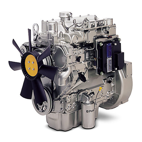
Section Model Views i02861104 Model View Illustrations The following model views show typical features of the engine. Due to individual applications, your engine may appear different from the illustrations. Illustration 17 g01425089 The 1104D NJ engine is turbocharged and aftercooled. - Page 21 SEBU8172-04 Product Information Section Model View Illustrations Illustration 18 g01428165 The 1104D NH engine is turbocharged. Front left engine view (1) Front lifting eye (6) Secondary fuel filter (11) Oil filter (2) Water outlet (7) Water pump (12) Crankshaft pulley...
- Page 22 SEBU8172-04 Product Information Section Engine Description Illustration 19 g01428176 Rear right engine view (15) Alternator (19) Drain plug or coolant sampling valve (23) Hand fuel priming pump (16) Exhaust manifold (20) Starting Motor (24) Flywheel (17) Turbocharger (21) Oil drain plug (25) Flywheel housing (18) Wastegate solenoid (22) Primary fuel filter...
- Page 23 SEBU8172-04 Product Information Section Engine Description • Engine speed governing • Control of the injection pressure • Cold start strategy • Automatic air/fuel ratio control • Torque rise shaping • Injection timing control • System diagnostics For more information on electronic engine features, refer to the Operation and Maintenance Manual, “Features and Controls”...
- Page 24 SEBU8172-04 Product Information Section Engine Description Engine efficiency, efficiency of emission controls, and engine performance depend on adherence to proper operation and maintenance recommendations. Engine performance and efficiency also depend on the use of recommended fuels, lubrication oils, and coolants. Refer to this Operation and Maintenance Manual, “Maintenance Interval Schedule”...
-
Page 25: Product Identification Information
Record for Reference Illustration 21 g01248563 Engine Model Location of the serial number plate Engine Serial number Perkins engines are identified by an engine serial number. Engine Low Idle rpm An example of an engine number is Engine Full Load rpm NH*****U000001J. - Page 26 SEBU8172-04 Product Information Section Emissions Certification Film Fan Drive Belt Alternator Belt i02861254 Emissions Certification Film Illustration 23 g01440937 Typical example...
-
Page 27: Operation Section
If alterations are made, ensure that correct lifting devices are provided. Consult your Perkins dealer or your Perkins distributor for information regarding fixtures for correct engine lifting. Illustration 24... - Page 28 Rust can form on the cylinder walls. Rust on the cylinder walls will cause increased engine wear and a reduction in engine service life. Perkins are not responsible for damage which may occur when an engine is in storage after a period in service.
- Page 29 SEBU8172-04 Operation Section Engine Storage 1. Completely clean the outside of the engine. Fill the oil pan to the Full Mark on the engine oil level gauge with new, clean lubricating oil. Add 2. Ensure that the vehicle is on level ground. 1762811 POWERPART Lay-Up 2 to the oil in 3.
-
Page 30: Gauges And Indicators
Determine and correct the cause of any significant 1. Reduce the load and the engine rpm. change in the readings. Consult your Perkins dealer or your Perkins distributor for assistance. 2. Determine if the engine must be shut down... -
Page 31: Features And Controls
SEBU8172-04 Operation Section Features and Controls Features and Controls i02296746 Monitoring System Table 2 Shutdown Warning Lamp Lamp Status Description of lamp status Engine Status Lamp Lamp check When the engine start switch is turned to the “ON” posi- The engine has not been tion both lamps will illuminate for 2 seconds only. - Page 32 For each of the programmed modes, refer to Troubleshooting , “Indicator Lamps” for more information on Indicator Lamps. For more information or assistance for repairs, consult your Perkins dealer or your Perkins distributor. i02861773 Sensors and Electrical Components...
- Page 33 SEBU8172-04 Operation Section Sensors and Electrical Components Illustration 27 g01425443 (1) Coolant temperature sensor (4) Fuel pressure sensor (7) Secondary position sensor (2) Intake manifold pressure sensor (5) Electronic control module (8) Engine oil pressure sensor (3) Inlet air temperature sensor (6) Primary position sensor Illustration 28 shows the sensors and the ECM in position on the engine.
- Page 34 SEBU8172-04 Operation Section Sensors and Electrical Components Illustration 28 g01425468 Failure of Sensors • Measured reading of the sensor is out of the specification. All Sensors Programmable Monitoring System A failure of any of the sensors may be caused by one (PMS) of the following malfunctions: The Programmable Monitoring System determines...
- Page 35 SEBU8172-04 Operation Section Sensors and Electrical Components • Fuel Pressure Sensor In order to check the correct operation of the sensor, refer to Troubleshooting, “EngineTemperature • Engine Oil Pressure Sensor Sensor Circuit - Test”. • Primary Speed/Timing Sensor Intake Manifold Pressure Sensor 3 •...
- Page 36 SEBU8172-04 Operation Section Engine Shutoffs and Engine Alarms Failure of the Engine Oil Pressure Sensor In order to check the correct operation of the sensor, refer to Troubleshooting, “Engine speed/Timing sensor - Test”. The ECM (5) will detect failure of the engine oil pressure sensor.
- Page 37 SEBU8172-04 Operation Section Overspeed The alarm is operated by a sensor or by a switch. If corrective measures are not taken within a reasonable time, engine damage could result. The When the sensor or the switch is activated a signal is alarm will continue until the condition is corrected.
-
Page 38: Engine Diagnostics
Retrieval Self-Diagnostics “ “ Diagnostic” ” Lamp Perkins electronic engines have the capability to perform a self-diagnostics test. When the system Use the “DIAGNOSTIC” Lamp or an electronic detects an active problem, a diagnostic lamp is service tool to determine the diagnostic flash code. - Page 39 SEBU8172-04 Operation Section Diagnostic Flash Code Retrieval Table 3 Flash Codes for the Industrial Engine Effect On Engine Performance Suggested Operator Action Reduced Shut Down Diagnostic Flash Code Schedule a Engine Engine Engine the Engine Service Service. Misfire Power Shutdown Speed Cylinder 1 Fault 112 Cylinder 2 Fault...
- Page 40 SEBU8172-04 Operation Section Fault Logging (Table 3, contd) Flash Codes for the Industrial Engine Effect On Engine Performance Suggested Operator Action Reduced Shut Down Diagnostic Flash Code Schedule a Engine Engine Engine the Engine Service Service. Misfire Power Shutdown Speed 429 Keyswitch Fault Intermittent Battery Power to ECM...
- Page 41 SEBU8172-04 Operation Section Engine Operation with Intermittent Diagnostic Codes In most cases, it is not necessary to stop the engine because of an intermittent code. However, the operator should retrieve the logged fault codes and the operator should reference the appropriate information in order to identify the nature of the event.
-
Page 42: Engine Starting
SEBU8172-04 Operation Section Engine Starting Engine Starting Starting the Engine 1. Disengage any equipment that is driven by the i02322201 engine. Before Starting Engine 2. Turn the keyswitch to the RUN position. Leave the keyswitch in the RUN position until the warning light for the glow plugs is extinguished. - Page 43 SEBU8172-04 Operation Section After Starting Engine Do not check the high pressure fuel lines with the NOTICE engine or the starting motor in operation. If you Using a battery source with the same voltage as the inspect the engine in operation, always use the electric starting motor.
-
Page 44: Engine Operation
Fuel Conservation Practices The efficiency of the engine can affect the fuel economy. Perkins design and technology in manufacturing provides maximum fuel efficiency in all applications. Follow the recommended procedures in order to attain optimum performance for the life of the engine. -
Page 45: Engine Stopping
SEBU8172-04 Operation Section Engine Stopping Engine Stopping i02330274 After Stopping Engine i06832774 Stopping the Engine Note: Before you check the engine oil, do not operate the engine for at least 10 minutes in order to allow the engine oil to return to the oil pan. NOTICE Stopping the engine immediately after it has been working under load, can result in overheating and ac-... - Page 46 SEBU8172-04 Operation Section After Stopping Engine • Check the coolant for correct antifreeze protection and the correct corrosion protection. Add the correct coolant/water mixture, if necessary. • Perform all required periodic maintenance on all driven equipment. This maintenance is outlined in the instructions from the OEM.
-
Page 47: Cold Weather Operation
Cold Weather Operation • Install the correct specification of engine lubricant before the beginning of cold weather. Perkins Diesel Engines can operate effectively in • Check all rubber parts (hoses, fan drive belts.) cold weather. During cold weather, the starting and weekly. - Page 48 An electric block heater can be activated once the • Pushrods may become bent. engine is stopped. An effective block heater is typically a 1250/1500 W unit. Consult your Perkins • Other damage to valve train components can dealer or your Perkins distributor for more result.
- Page 49 This CFPP gives an estimate of the lower operability temperature of fuel Note: Perkins discourages the use of all air flow restriction devices such as radiator shutters. Be aware of these properties when diesel fuel is Restriction of the air flow can result in the following: purchased.
- Page 50 SEBU8172-04 Operation Section Fuel Related Components in Cold Weather i02323237 Fuel Related Components in Cold Weather Fuel Tanks Condensation can form in partially filled fuel tanks. Top off the fuel tanks after you operate the engine. Fuel tanks should contain some provision for draining water and sediment from the bottom of the tanks.
-
Page 51: Maintenance Section
SEBU8172-04 Maintenance Section Refill Capacities Maintenance Section Refill Capacities i04262329 Refill Capacities Lubrication System The refill capacities for the engine crankcase reflect the approximate capacity of the crankcase or sump plus standard oil filters. Auxiliary oil filter systems will require additional oil. Refer to the OEM specifications for the capacity of the auxiliary oil filter. - Page 52 The fuel must meet the minimum requirements that are stated in table 6 . NOTICE The footnotes are a key part of the Perkins Specifica- tion for Distillate Diesel Fuel Table. Read ALL of the footnotes.
- Page 53 Regional regulations, national regulations or international regulations can require a fuel with a specific sulfur limit. Consult all applicable regu- lations before selecting a fuel for a given engine application. Perkins fuel systems and engine components can operate on high sulfur fuels.
- Page 54 The viscosity of the fuel is significant because fuel NOTICE serves as a lubricant for the fuel system components. Operating with fuels that do not meet the Perkins rec- Fuel must have sufficient viscosity in order to ommendations can cause the following effects: Start-...
- Page 55 SEBU8172-04 Maintenance Section Fuel Specification Distillation By using the test methods “ASTM D5453, ASTM D2622, or ISO 20846 ISO 20884”, the content of sulfur in low sulfur diesel (LSD) fuel must be below This is an indication of the mixture of different hydrocarbons in the fuel.
- Page 56 Protection Agency (EPA) and European Certification performed on a HFRR, operated at 60 °C (140 °F). fuels. Perkins does not certify engines on any other Refer to “ISO 12156-1 ”. Fuels must have minimum fuel. The user of the engine has the responsibility of viscosity of 1.4 centistokes that is delivered to the...
- Page 57 SEBU8172-04 Maintenance Section Fuel Specification • The oil change interval can be affected by the use • Biodiesel is an excellent medium for microbial of biodiesel. Use Services Oil Analysis in order to contamination and growth. Microbial monitor the condition of the engine oil. Use contamination and growth can cause corrosion in Services Oil Analysis also in order to determine the fuel system and premature plugging of the fuel...
- Page 58 “SAE J754”. Some classifications follow “SAE J183” abbreviations, and some classifications follow the i02865363 “EMA Recommended Guideline on Diesel Engine Oil”. In addition to Perkins definitions, there are other Fluid Recommendations definitions that will be of assistance in purchasing lubricants. Recommended oil viscosities can be found in this publication, “Fluid Recommendations/...
- Page 59 API CH-4 oils may be used in Note: These engine oils are not approved by Perkins engines that use API CG-4 and API CF-4 oils. API CH-4 oils will generally exceed the perkins and these engine oils must not be used: performance of API CG-4 oils in the following criteria: CC, CD, CD-2 and CF-4.
- Page 60 SEBU8172-04 Maintenance Section Fluid Recommendations Total Base Number (TBN) and Fuel Sulfur Table 10 Levels for Direct Injection (DI) Diesel Percentage of Sulfur in the Oil change interval Engines fuel Lower than 0.5 Normal The Total Base Number (TBN) for an oil depends on 0.5 to 1.0 0.75 of normal the fuel sulfur level.
- Page 61 Perkins discourages the use of aftermarket additives in finished oils. Re-refined base stock oils are acceptable for use in Perkins engines if these oils meet the performance To achieve the best performance from a Perkins requirements that are specified by Perkins. Re-...
- Page 62 SEBU8172-04 Maintenance Section Fluid Recommendations • The Oil Condition Analysis determines the loss of These failures can be avoided with correct cooling system maintenance. Cooling system maintenance is the oil's lubricating properties. An infrared analysis as important as maintenance of the fuel system and is used to compare the properties of new oil to the the lubrication system.
- Page 63 American Society for Testing and • Reduction of heat transfer Materials • Leakage of the water pump seal The following two coolants are used in Perkins diesel engines: • Plugging of radiators, coolers, and small passages Preferred – Perkins ELC Glycol Acceptable –...
- Page 64 (if equipped) must be set to the HOT position. Refer agents with low amounts of nitrite. Perkins ELC has to the OEM in order to set the heater control. After been formulated with the correct amount of these...
- Page 65 Perkins engine cooling systems should be tested at 9. Fill the cooling system with the Perkins Premixed 500 hour intervals for the concentration of SCA. ELC. Additions of SCA are based on the results of the test.
- Page 66 The size of the cooling system determines the amount of SCA that is needed. Use the equation that is in Table 19 to determine the amount of Perkins SCA that is required, if necessary: Table 19 Equation For Adding The SCA To The Heavy-Duty Coolant For Maintenance V ×...
-
Page 67: Maintenance Recommendations
SEBU8172-04 Maintenance Section Maintenance Recommendations Maintenance • ECM Recommendations • Sensors • Electronically controlled valves i04103075 • Relays Welding on Engines with Electronic Controls • Aftertreatment ID module NOTICE Do not use electrical components (ECM or ECM sen- sors) or electronic component grounding points for NOTICE grounding the welder. - Page 68 SEBU8172-04 Maintenance Section Welding on Engines with Electronic Controls 5. Connect the welding ground cable directly to the part that will be welded. Place the ground cable as close as possible to the weld in order to reduce the possibility of welding current damage to the following components.
-
Page 69: Maintenance Interval Schedule
SEBU8172-04 Maintenance Section Maintenance Interval Schedule “ V-Belts - Inspect/Adjust/Replace“ ... . 102 i08335544 Maintenance Interval Schedule Every 500 Service Hours or 1 Year “ Battery Electrolyte Level - Check“ ... . 73 When Required “... - Page 70 SEBU8172-04 Maintenance Section Maintenance Interval Schedule “ Water Pump - Inspect“..... 105 Every 3000 Service Hours “ Alternator Belt - Inspect/Adjust/Replace“ ..72 Every 3000 Service Hours or 2 Years “...
- Page 71 SEBU8172-04 Maintenance Section Aftercooler Core - Clean/Test i02322260 Aftercooler Core - Clean/Test Personal injury can result from air pressure. Personal injury can result without following prop- er procedure. When using pressure air, wear a 1. Remove the core. Refer to the OEM information for protective face shield and protective clothing.
- Page 72 Make repairs, if necessary. i02322311 Alternator - Inspect Perkins recommends a scheduled inspection of the alternator. Inspect the alternator for loose connections and correct battery charging. Check the ammeter (if equipped) during engine operation in order to ensure correct battery performance and/or correct performance of the electrical system.
- Page 73 SEBU8172-04 Maintenance Section Battery Electrolyte Level - Check The battery cables or the batteries should not be All lead-acid batteries contain sulfuric acid which can burn the skin and clothing. Always wear a removed with the battery cover in place. The bat- face shield and protective clothing when working tery cover should be removed before any servic- on or near batteries.
- Page 74 SEBU8172-04 Maintenance Section Belt Tensioner - Inspect 4. Clean all disconnected connection and battery i02854855 terminals. Cooling System Coolant 5. Use a fine grade of sandpaper to clean the (Commercial Heavy-Duty) - terminals and the cable clamps. Clean the items Change until the surfaces are bright or shiny.
- Page 75 For information regarding the disposal and the the cavities of the engine block. Decrease the recycling of used coolant, consult your Perkins engine speed to low idle. Stop the engine. distributor.
- Page 76 SEBU8172-04 Maintenance Section Cooling System Coolant (ELC) - Change • Foaming of the coolant is observed. • The oil has entered the cooling system and the coolant is contaminated. • The fuel has entered the cooling system and the coolant is contaminated. Note: When the cooling system is cleaned, only clean water is needed when the ELC is drained and replaced.
- Page 77 Do not install the For information regarding the disposal and the cooling system filler cap. recycling of used coolant, consult your Perkins dealer 3. Start and run the engine at low idle. Increase the or your Perkins distributor.
- Page 78 Engines With a Coolant Recovery Tank Note: The cooling system may not have been provided by Perkins. The procedure that follows is for typical cooling systems. Refer to the OEM information for the correct procedures. Check the coolant level when the engine is stopped and cool.
- Page 79 SEBU8172-04 Maintenance Section Cooling System Supplemental Coolant Additive (SCA) - Test/Add Use a Coolant Conditioner Test Kit in order to check the concentration of the SCA. Pressurized System: Hot coolant can cause seri- Add the SCA, If Necessary ous burns. To open the cooling system filler cap, stop the engine and wait until the cooling system components are cool.
- Page 80 SEBU8172-04 Maintenance Section Crankcase Breather (Canister) - Replace 4. Clean the cooling system filler cap and inspect the 3. Lubricate the O ring seal (2) on the new canister gasket. If the gasket is damaged, discard the old (3) with clean engine lubricating oil. Install the new filler cap and install a new filler cap.
- Page 81 Servicing the Air Cleaner Elements Note: The air filter system may not have been provided by Perkins. The procedure that follows is for Illustration 41 g00736431 a typical air filter system. Refer to the OEM (1) Cover information for the correct procedure.
- Page 82 SEBU8172-04 Maintenance Section Engine Air Cleaner Element (Dual Element) - Clean/Replace Pressurized Air 3. Cover the air inlet with tape in order to keep dirt out. 4. Clean the inside of the air cleaner cover and body with a clean, dry cloth. Personal injury can result from air pressure.
- Page 83 SEBU8172-04 Maintenance Section Engine Air Cleaner Service Indicator - Inspect Note: Refer to “Inspecting the Primary Air Cleaner Elements”. Inspecting the Primary Air Cleaner Elements Illustration 44 g00103777 Typical service indicator Observe the service indicator. The air cleaner element should be cleaned or the air cleaner element should be replaced when one of the following conditions occur: Illustration 43...
- Page 84 Refer to the OEM information for the recommended torques. i05967804 When the engine mounts are supplied by Perkins the maintenance procedure will be supplied in the Engine Air Precleaner - Check/ Disassembly and Assembly manual for your engine.
- Page 85 Hot oil and hot components can cause personal injury. Do not allow hot oil or hot components to Perkins recommends using a sampling valve in order contact the skin. to obtain oil samples. The quality and the consistency of the samples are better when a sampling valve is used.
- Page 86 Use of an oil filter that is not recommended Note: Ensure that the vessel that will be used is large by Perkins could result in severe damage to the en- enough to collect the waste oil. gine bearings, crankshaft, etc., as a result of the larg-...
- Page 87 SEBU8172-04 Maintenance Section Engine Oil and Filter - Change 5. Install the oil filter. Tighten the oil filter to 12 N·m (8.8 lb ft). Do not overtighten the oil filter. Horizontal Oil Filter Illustration 49 g01187802 Typical example 3. Clean the sealing surface of the oil filter head (2). Ensure that the union is secure in the filter head.
- Page 88 Refer to the Service Manual or your au- the oil filters are filled. Inspect the oil filter for oil thorized Perkins dealer or your Perkins distributor for the complete valve lash adjustment procedure. leaks.
- Page 89 SEBU8172-04 Maintenance Section Exhaust Manifold - Inspect i02862580 i02683336 Exhaust Manifold - Inspect Fan Clearance - Check There are different types of cooling systems. Refer to the OEM for information on clearance for the fan. Ensure that the engine is stopped. Ensure that the cooling system is full.
- Page 90 SEBU8172-04 Maintenance Section Fuel System - Prime Illustration 54 g01348394 Adjustment of the cover will change the clearance Note: Refer to Systems Operation, Testing and (gap) between the edge of the cover and the tip of Adjusting, “Cleanliness of Fuel System the fan blade.
- Page 91 SEBU8172-04 Maintenance Section Fuel System Primary Filter (Water Separator) Element - Replace • A leak exists in the low pressure fuel system. Note: Do not loosen the high pressure fuel line in order to purge air from the fuel system. This •...
- Page 92 SEBU8172-04 Maintenance Section Fuel System Primary Filter (Water Separator) Element - Replace After the engine has stopped, you must wait for 60 seconds in order to allow the fuel pressure to be purged from the high pressure fuel lines before any service or repair is performed on the engine fuel lines.
- Page 93 SEBU8172-04 Maintenance Section Fuel System Primary Filter (Water Separator) Element - Replace After the engine has stopped, you must wait for 60 seconds in order to allow the fuel pressure to be purged from the high pressure fuel lines before any service or repair is performed on the engine fuel lines.
- Page 94 SEBU8172-04 Maintenance Section Fuel System Primary Filter (Water Separator) Element - Replace Illustration 60 g01429126 Illustration 61 g01429127 7. Use a suitable tool in order to remove old canister 8. Lubricate O ring seal (5 ) with clean engine oil on (4).
- Page 95 SEBU8172-04 Maintenance Section Fuel System Primary Filter/Water Separator - Drain 13. The secondary filter must be replaced at the same time as the primary filter. Refer to the Operation and Maintenance Manual , “Fuel System Filter - Replace”. i02869410 Fuel System Primary Filter/ Water Separator - Drain Fuel leaked or spilled onto hot surfaces or electri- cal components can cause a fire.
- Page 96 SEBU8172-04 Maintenance Section Fuel System Secondary Filter - Replace Note: Not all primary filters require vent screw (2). This primary fuel filter that has a vent screw may be installed on a fuel system that has a low fuel tank. 1.
- Page 97 SEBU8172-04 Maintenance Section Fuel System Secondary Filter - Replace Note: Refer to Testing and Adjusting Manual , “Cleanliness of Fuel System Components” for detailed information on the standards of cleanliness that must be observed during ALL work on the fuel system. NOTICE Ensure that the engine is stopped before any servic- ing or repair is performed.
- Page 98 SEBU8172-04 Maintenance Section Fuel Tank Water and Sediment - Drain 7. Prime the fuel system. Refer to the Operation and Maintenance Manual, “Fuel System - Prime” for more information. i02335436 Fuel Tank Water and Sediment - Drain NOTICE Care must be taken to ensure that fluids are con- tained during performance of inspection, mainte- nance, testing, adjusting and repair of the product.
- Page 99 The coolant system and the hoses for the coolant Contact with high pressure fuel may cause fluid system are not usually supplied by Perkins. The penetration and burn hazards. High pressure fuel following text describes a typical method of replacing spray may cause a fire hazard.
- Page 100 Make repairs, if necessary. Radiator - Clean i02335775 Severe Service Application - The radiator is not usually supplied by Perkins. The Check following text describes a typical cleaning procedure for the radiator. Refer to the OEM information for further information on cleaning the radiator.
- Page 101 Due to individual applications, it is not possible to identify all of the factors which can contribute to severe service operation. Consult your Perkins dealer or your Perkins distributor for the unique Perkins recommends a scheduled inspection of the maintenance that is necessary for the engine.
- Page 102 Ensure that all For options regarding the removal, installation, and clamps are installed correctly and that all clamps replacement, consult your Perkins dealer or your are tightened securely. Perkins distributor. Refer to the Disassembly and Assembly, “Turbocharger - Remove and...
- Page 103 SEBU8172-04 Maintenance Section Walk-Around Inspection 1. Loosen nut (2) and the bolt (3). 2. Move the alternator in order to increase or decrease the belt tension. Tighten the nut (2) and the bolt (3) to 22 N·m (16 lb ft).(1). Replace Refer to Disassembly and Assembly manual, “V- Belts - Remove and Install”...
- Page 104 Remove and Install”. For more information, consult your Perkins dealer or your Perkins distributor. • Inspect the rest of the fuel system for leaks. Look • Inspect the lubrication system for leaks at the front for loose fuel line clamps.
- Page 105 SEBU8172-04 Maintenance Section Water Pump - Inspect • Check the condition of the gauges. Replace any gauges that are cracked. Replace any gauge that can not be calibrated. i02499304 Water Pump - Inspect A failed water pump may cause severe engine overheating problems that could result in the following conditions: •...
-
Page 106: Warranty Section
This engine may be covered by an Emissions Warranty. Consult your authorized Perkins dealer or distributor to determine if your engine is emissions certified and if your engine is subject to an Emissions... -
Page 107: Index
SEBU8172-04 Index Section Index Add the SCA, If Necessary ......79 Test for SCA Concentration ......79 After Starting Engine ........43 Crankcase Breather (Canister) - Replace..80 After Stopping Engine ........45 Crushing Prevention and Cutting Prevention.. 15 Aftercooler Core - Clean/Test......71 Aftercooler Core - Inspect ....... - Page 108 SEBU8172-04 Index Section Obtain the Sample and the Analysis ... 85 Hand Fuel Priming Pump ......91 Engine Operation ..........44 Fuel System Primary Filter (Water Engine Operation with Active Diagnostic Separator) Element - Replace....... 91 Codes ............40 Type One Filter ..........91 Engine Operation with Intermittent Type Two Filter ..........
- Page 109 SEBU8172-04 Index Section Every 50 Service Hours or Weekly....69 Programmable Monitoring System (PMS)... 34 Every 500 Service Hours ......69 Secondary Speed/Timing Sensor 7..... 36 Every 500 Service Hours or 1 Year ..... 69 Sensor Locations ......... 32 Initial 500 Service Hours......69 Severe Service Application - Check....
- Page 111 Product and Dealer Information Note: For product identification plate locations, see the section “Product Identification Information” in the Operation and Maintenance Manual. Delivery Date: Product Information Model: Product Identification Number: Engine Serial Number: Transmission Serial Number: Generator Serial Number: Attachment Serial Numbers: Attachment Information: Customer Equipment Number: Dealer Equipment Number:...
- Page 112 SEBU8172 ©2021 Perkins Engines Company Limited All Rights Reserved January 2021...
Need help?
Do you have a question about the 1104D and is the answer not in the manual?
Questions and answers
Are the injector lines 6mm or 1/4" in diameter?