Table of Contents
Advertisement
Quick Links
r.LiNK Video-inserter
RL3-NAC
Compatible with
Citroen vehicles with NAC infotainment
Peugeot vehicles with NAC infotainment
Video-inserter with 2 video inputs,
rear-view camera input and CAN control
Product features
Video-inserter for factory infotainment systems
2 CVBS video-inputs for after-market devices (e.g. DVD-Player, DVB-T tuner)
1 Rear-view camera CVBS video-input
Automatic switching to rear-view camera input on engagement of reverse gear
Activatable parking guide lines for the rear-view camera (not available for all
vehicles)
Video-in-motion in drive mode (ONLY for connected video-sources)
AV-inputs PAL and NTSC compatible
Version 02.02.2018
HW:CAM-GD (V94)
RL3-NAC
Advertisement
Table of Contents

Related Manuals for r.LiNK 3008 NAC


Summary of Contents for r.LiNK 3008 NAC
- Page 1 Video-inserter RL3-NAC Compatible with Citroen vehicles with NAC infotainment Peugeot vehicles with NAC infotainment Video-inserter with 2 video inputs, rear-view camera input and CAN control Product features Video-inserter for factory infotainment systems 2 CVBS video-inputs for after-market devices (e.g. DVD-Player, DVB-T tuner) ...
-
Page 2: Table Of Contents
Contents 1. Prior to installation 1.1. Delivery contents 1.2. Checking the compatibility of vehicle and accessories 1.3. Warning notes 1.4. Connection Video-Interface 1.5. Settings of the 8 Dip switches (black) 1.5.1. Enabling the interface’s video inputs (dip 2-3) 1.5.2. Rear-view camera setting (dip 5) 1.5.3. -
Page 3: Prior To Installation
Legal Information By law, watching moving pictures while driving is prohibited, the driver must not be distracted. We do not accept any liability for material damage or personal injury resulting, directly or indirectly, from installation or operation of this product. Apart from using this product in an unmoved vehicle, it should only be used to display fixed menus or rear-view- camera video when the vehicle is moving (for example the MP3 menu for DVD upgrades). -
Page 4: Checking The Compatibility Of Vehicle And Accessories
1.2. Checking the compatibility of vehicle and accessories Compatibility Brand Compatible vehicles Infotainment systems C3 since 2017 Citroen C4 Cactus since 2014 C4 Picasso since 2017 NAC infotainment systems C6 since 2016 Jumpy since 2016 Space Tourer since 2016 208 since 2017 2008 since 2017 3008 since 2016 Peugeot... -
Page 5: Warning Notes
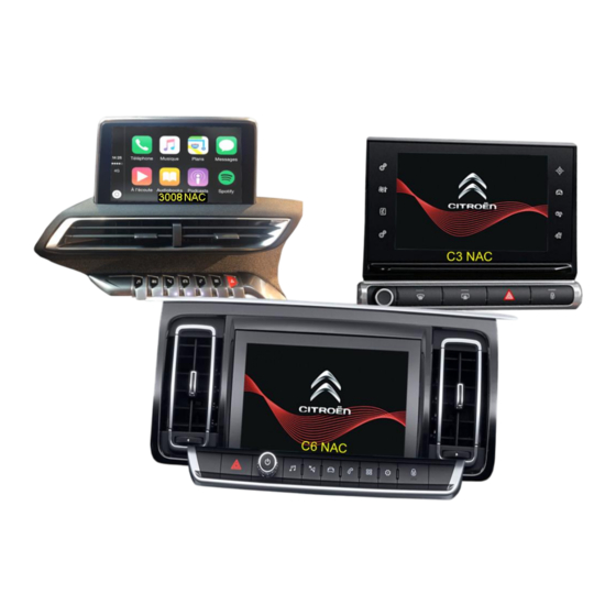
1.3. Warning notes: Damage to the head-unit is possible, if this RL3-NAC interface is installed to older Citroen / Peugeot SMEG or SMEG+ head-units (by Magneti Marelli)! Use this RL3-NAC interface only on Citroen/Peugeot NAC head-units (by Continental from about 2016-) Designs and features –see the following pictures: NAC-Systeme Furthermore, even when installed to the correct NAC systems, there is also... -
Page 6: Connection Video-Interface
1.4. Connection Video-Interface The video-interface converts the video signals of connected after-market sources in a factory monitor compatible picture signal which is inserted in the factory monitor, by using separate trigger options. Further it reads the vehicle’s digital signals out of the vehicle’s CAN-bus and converts them for the video interface. -
Page 7: Enabling The Interface's Video Inputs (Dip 2-3)
1.5.1. Enabling the interface’s video inputs (dip 2-3) Only the enabled video inputs can be accessed when switching through the interface’s video sources. It`s recommended to enable only the required inputs, for the disabled will be skipped when switching through the video interfaces inputs. 1.5.2. -
Page 8: Installation
2. Installation Switch off the ignition and disconnect the vehicle’s battery! The interface needs a permanent 12V source. If -according to factory rules- a disconnection of the battery has to be avoided, it should be sufficient to use the vehicle’s sleep-mode. In case, the sleep-mode doesn’t succeed, the battery has to be disconnected with a resistor lead. -
Page 9: Connection Schema
2.2. Connection schema Version 02.02.2018 HW:CAM-GD (V94) RL3-NAC... -
Page 10: Connection To The Head-Unit
2.3. Connections to the head-unit Remove the vehicle’s head unit 2.3.1. Connection LVDS – video interface 2.3.1.1. High version head unit Disconnect the vehicle harness’ female double 4pin HSD connector from the head unit’s rearside and connect it to the double 4pin HSD connector of the enclosed 4pin HSD harness. -
Page 11: Low Version Head Unit (1 X 4Pin Hsd)
2.3.1.2. Low version head unit (1 X 4pin HSD) Disconnect the single female 4pin HSD connector of the vehicle harness at the rearside of the head unit and connect it to the 4pin HSD connector „Low version HU – to vehicle harness“ of the enclosed 4pin HSD harness. -
Page 12: Connection To The Head-Unit - Power / Can
2.3.2. Connection to the head unit – Power / CAN Disconnect the female PSA Quadlock connector at the rearside of the head unit and click out the green female 22pin connector of the female PSA Quadlock connector. Connect the singel four cables of the POWER / CAN cable to the green female PSA Quadlock connector as shown: „BATT“... -
Page 13: Connecting Video Sources
2.4. Connecting the video sources It is possible to connect two after-market video-sources and an after-market rear-view camera to the video-interface. 2.4.1. Video-sources to Video IN1 and Video IN2 Connect the interface cable’s female 12pin connector to the video interface’s 12pin connector. -
Page 14: Audio Insertion
2.4.2. Audio insertion This interface can only insert video signals into the factory infotainment. If an AV source is connected, the audio insertion has to be performed by a factory aux input or an FM modulator. The inserted video-signal can be activated simultaneously to each audio-mode of the factory infotainment. -
Page 15: Case 2: Video Interface Does Not Receive The Reverse Gear Signal
2.4.3.2. Case 2: Video interface does not receive the reverse gear signal If the video interface does not receive +12V on the green wire of the 20pin cable when reverse gear is engaged (not all vehicles are compatible), an external switching signal from the reverse gear light is required. -
Page 16: Video Signal Connection For The Rear-View Camera
2.4.3.3. Video signal connection for the rear-view camera Connect the video-RCA of the after-market rear-view camera to the female RCA port “Camera-IN” of the video-cable. Version 02.02.2018 HW:CAM-GD (V94) RL3-NAC... -
Page 17: Connecting Video-Interface And External Keypad
2.5. Connecting video-interface and external keypad Connect the keypad’s female 4pin connector to the video-interface’s male 4pin connector. Note: Even if the switching through several video sources by the keypad mightn’t be required, the invisible connection and availability is strongly recommended. Version 02.02.2018 HW:CAM-GD (V94) RL3-NAC... -
Page 18: Picture Settings And Guide Lines
2.6. Picture settings and guide lines The picture settings can be adjusted by the 3 buttons on the video-interface. Press the MENU button to open the OSD settings menu. To switch to the next menu item, pressing DOWN will change the selected value. The buttons are embedded in the housing to avoid accidental changes during or after installation. -
Page 19: Interface Operation
3. Interface operation 3.1. By Navi button A press of the infotainment’s “Navi”-button switches the input from factory mode to the inserted video sources. If, by dip switch setting, all inputs are enabled, the order is the following: ... -
Page 20: Specifications
4. Specifications BATT/ACC range 7V - 25V Stand-by power drain 2,8mA Power 300mA @12V Video input 0.7V – 1V Video input formats PAL/NTSC Temperature range -40°C to +85°C Dimensions Video-Box 118 x 23 x 105 mm (W x H x D) Version 02.02.2018 HW:CAM-GD (V94) RL3-NAC... -
Page 21: Faq - Trouble Shooting
FAQ – Trouble shooting Interface functions For any troubles which may occur, check the following table for a solution before requesting support from your vendor. Symptom Reason Possible solution Not all connectors have been reconnected to factory head- Connect missing connectors. unit or monitor after installation. -
Page 22: Technical Support
Symptom Reason Possible solution Camera input picture Use relay or electronics to "clean" reverse gear lamp black. Camera power taken directly power. Alternatively, if CAN-bus box is compatible Camera input picture from reverse gear lamp. with the vehicle, camera power can be taken from green wire of 6pin to 8pin cable.
Need help?
Do you have a question about the 3008 NAC and is the answer not in the manual?
Questions and answers