Table of Contents
Advertisement
Quick Links
Compatible with Mercedes Benz vehicles
with 4pin HSD connector at the monitor
Video-inserter for front- and rear-view camera
Product Features
Video-inserter for factory-infotainment systems
1 CVBS Input for rear-view camera
1 CVBS Input for front camera
2 CVBS Video-inputs for after-market Video sources (e.g. USB-Player, DVB-T Tuner)
Automatic switching to rear-view camera input on engagement of the reverse gear
Automatic front camera switching after reverse gear for 10 seconds
Activatable parking guide lines for rear-view camera (not available for all vehicles)
Video-in-motion (ONLY for connected video-sources)
Video-inputs NTSC and PAL compatible
Version 18.03.2020
r.LiNK Video-inserter
RL4-MBN51
with NTG5-205 or NTG5.1
Comand Online
Audio20 CD
Audio20 USB
and two additional video inputs
HW CAM(V98)/(V52)
RL4-MBN51
Advertisement
Table of Contents

Related Manuals for r.LiNK RL4-MBN51


Summary of Contents for r.LiNK RL4-MBN51
- Page 1 Video-inserter RL4-MBN51 Compatible with Mercedes Benz vehicles with NTG5-205 or NTG5.1 with 4pin HSD connector at the monitor Comand Online Audio20 CD Audio20 USB Video-inserter for front- and rear-view camera and two additional video inputs Product Features Video-inserter for factory-infotainment systems ...
-
Page 2: Table Of Contents
Case 2: Video interface does not receive the reverse gear signal 2.7. Connecting video-interface and external keypad 2.8. Picture settings and guide lines 3. Interface operation 3.1. By Comand buttons 3.2. By external keypad 4. Specifications 5. FAQ – Trouble shooting 6. Technical support Version 18.03.2020 HW CAM(V98)/(V52) RL4-MBN51... -
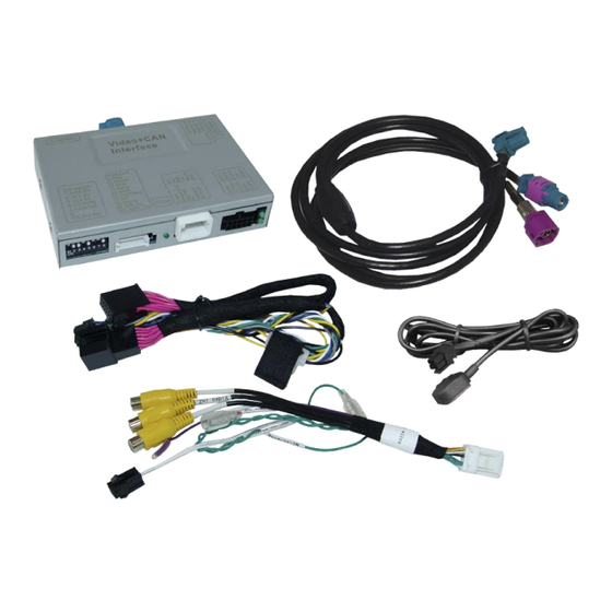
Page 3: Prior To Installation
Read the manual prior to installation. Technical knowledge is necessary for installation. The place of installation must be free of moisture and away from heat sources. 1.1. Delivery contents Take down the serial number of the interface and store this manual for support purposes: ____________________ Version 18.03.2020 HW CAM(V98)/(V52) RL4-MBN51... -
Page 4: Checking The Compatibility Of Vehicle And Accessories
A manually front camera switching is possible by external keypad. Guidelines If the video interface does not receive the required information from the vehicle CAN-bus, the guide-lines will not be supported. Version 18.03.2020 HW CAM(V98)/(V52) RL4-MBN51... -
Page 5: Connection Video-Interface
Try all possible combinations of dip7 and 8 to find the best Monitor selection picture (quality and size) See the following chapters for detailed information. After each Dip-switch-change a power-reset of the Interface-box has to be performed! Version 18.03.2020 HW CAM(V98)/(V52) RL4-MBN51... -
Page 6: Enabling The Interface's Video Inputs (Dip 2-3)
Warning: If dip switch 3 has not been set to the vehicle specific correct position, CAN-bus faults may occur, which extremely disturb the vehicle’s instrument electronics! *Vehicle specific infotainment assignments can be taken from the yellow box on page 4! Version 18.03.2020 HW CAM(V98)/(V52) RL4-MBN51... -
Page 7: Installation
Before the final installation, we recommend a test-run of the interface. Due to changes in the production of the vehicle manufacturer, there’s always the possibility of incompatibility. 2.1. Place of installation The interface is installed on the backside of the head-unit. Version 18.03.2020 HW CAM(V98)/(V52) RL4-MBN51... -
Page 8: Connection Schema
2.2. Connection Scheme Version 18.03.2020 HW CAM(V98)/(V52) RL4-MBN51... -
Page 9: Picture Signal Cable
4pin HSD LVDS connector of head unit. Note: If the factory HSD picture signal cable of the vehicle harness is too short for the installation, an HSD extension cable can be ordered separately with item number CAB-HSD- ML100. Version 18.03.2020 HW CAM(V98)/(V52) RL4-MBN51... -
Page 10: Power And Can Connection
Clip in the female 12pin connector of the PNP harness in the previously become free position of the female Quadlock connector before finishing the Quadlock reconnection at the rear of the head-unit. Note: After connection, perform the tests listed on the next page Version 18.03.2020 HW CAM(V98)/(V52) RL4-MBN51... -
Page 11: Analog Power Supply For The Video Interface
If, after connecting the PNP harness, no interface LED lightens up while the ignition is turned on, the purple coloured wire Manual ACC of the 12pin interface cable has to be connected additionately to S-contact terminal 86s +12V (e.g. glove compartment illumination). Version 18.03.2020 HW CAM(V98)/(V52) RL4-MBN51... -
Page 12: Power Supply Output
+12V (max. 3A) when reverse gear is engaged incl. 10 seconds delay after reverse gear is disengaged and +12V by manual switching to front camera by keypad (short press) Dip 1 OFF +12V (max. 3A) ACC Version 18.03.2020 HW CAM(V98)/(V52) RL4-MBN51... -
Page 13: Connecting Video Sources
Connect the front camera’s video RCA connector to the 12pin interface cable’s female RCA connector „Front V3“. Connect the video RCA of any other AV sources to the female RCR connectors “Left (V1)” ”Right (V2)”. Version 18.03.2020 HW CAM(V98)/(V52) RL4-MBN51... -
Page 14: Audio Insertion
“Camera IN” while the reverse gear is engaged. Additionally, the +12V (max. 3A) power supply for the rear-view camera can be taken from the green wire of the 12pin interface cable. Version 18.03.2020 HW CAM(V98)/(V52) RL4-MBN51... - Page 15 Connect the output connector (87) of the relay to the rear-view camera’s power- cable, like you did it to the green “Reverse-IN” cable before. Connect stabile and permanent +12V to the relay’s input connector (30). Version 18.03.2020 HW CAM(V98)/(V52) RL4-MBN51...
-
Page 16: Connecting Video-Interface And External Keypad
Connect the female 4pin connector of the keypad to the male 4pin connector of the 12pin interface cable. Note: Even if switching through several video sources by the keypad mightn’t be required, the invisible connection and availability is strongly recommended. Version 18.03.2020 HW CAM(V98)/(V52) RL4-MBN51... -
Page 17: Picture Settings And Guide Lines
H-SIZE (horizontal) picture adjustment V-SIZE (vertical) for rear-view camera Note: If the vehicle’s CAN communication does not support the video interface, the guide- lines cannot be used, even if they’re once shown with the first operation! Version 18.03.2020 HW CAM(V98)/(V52) RL4-MBN51... -
Page 18: Interface Operation
7V - 25V Stand-by power drain 10mA Power consumption 280mA Video input 0.7V - 1V Video input formats PAL/NTSC Temperature range -40°C to +85°C Dimensions video-box 117 x 25 x 105 mm (W x H x D) Version 18.03.2020 HW CAM(V98)/(V52) RL4-MBN51... -
Page 19: Faq - Trouble Shooting
Camera input picture fluorescent light which shines Test camera under natural light outside the garage. flickers. directly into the camera. Camera input picture is Protection sticker not Remove protection sticker from lens. bluish. removed from camera lens. Version 18.03.2020 HW CAM(V98)/(V52) RL4-MBN51... -
Page 20: Technical Support
Please note that direct technical support is only available for products purchased directly from NavLinkz GmbH. For products bought from other sources, contact your vendor for technical support. NavLinkz GmbH distribution/tech dealer-support Heidberghof 2 D-47495 Rheinberg +49 2843 17595 00 Email mail@navlinkz.de 10R-03 5384 Made in China Version 18.03.2020 HW CAM(V98)/(V52) RL4-MBN51...
Need help?
Do you have a question about the RL4-MBN51 and is the answer not in the manual?
Questions and answers