Compaq Armada M700 Series Maintenance And Service Manual
Hp armada m700: supplementary guide
Hide thumbs
Also See for Armada M700 Series:
- Reference manual (218 pages) ,
- Quickspecs (24 pages) ,
- Maintenance and service manual (74 pages)
Table of Contents
Advertisement
Quick Links
Advertisement
Table of Contents
Troubleshooting

Related Manuals for Compaq Armada M700 Series


Summary of Contents for Compaq Armada M700 Series
- Page 1 Compaq Armada M700 Series of Personal Computers Maintenance and Service Guide...
- Page 2 Nothing herein should be construed as constituting a further or additional warranty. AINTENANCE AND ERVICE Compaq Armada M700 Series of Personal Computers Seventh Edition (March 2001) First Edition (July 1999) Published in the U.S.A., U.K., Singapore, and Taiwan.
-
Page 4: Table Of Contents
ONTENTS preface SING UIDE Symbols ... ix Technical Notes ... ix Serial Number... x Locating Additional Information... x chapter 1 RODUCT ESCRIPTION 1.1 Computer Features and Models ...1-1 Models ...1-2 Features...1-6 Intelligent Manageability ...1-6 Accessing the Web Agent...1-7 Asset Management ...1-7 Fault Management ...1-8 Security Management...1-8 Configuration Management...1-9... - Page 5 chapter 2 ROUBLESHOOTING 2.1 Preliminary Steps...2-2 2.2 Clearing Passwords...2-3 2.3 Power-On Self-Test (POST)...2-3 2.4 POST Error Messages ...2-4 2.5 Compaq Utilities...2-7 Selecting Computer Setup or Compaq Diagnostics for Windows ...2-7 Using Compaq Diagnostics for Windows ...2-11 Factory Default Settings...2-11 2.6 Troubleshooting Without Diagnostics...2-13 Before Replacing Parts...2-13 Obtaining Update Information with Info Messenger ...2-13 Checklist for Solving Problems...2-14...
- Page 6 5.6 Battery Packs ...5-6 Removing a Primary Battery Pack from the Battery Bay ...5-6 Inserting a Primary Battery Pack in the Battery Bay ...5-7 5.7 Hard Drives...5-8 Removing a Hard Drive from the Hard Drive Bay ...5-8 Inserting a Hard Drive into the Hard Drive Bay ...5-10 5.8 MultiBay Devices ...5-11 Removing MultiBay Devices ...5-11 Inserting MultiBay Devices...5-12...
- Page 7 appendix A ONNECTOR SSIGNMENTS appendix B OWER EQUIREMENTS 3-Conductor Power Cord Set... B-1 Country-Specific Requirements ... B-2 Index ...I-1 viii Table of Contents ... A-1...
-
Page 8: Using This Guide
UIDE This Maintenance and Service Guide is a troubleshooting reference that can be used when servicing the Compaq Armada M700 Series of Personal Computers. Compaq Computer Corporation reserves the right to make changes to the Compaq Armada M700 Series of Personal Computers without notice. -
Page 9: Serial Number
Locating Additional Information In addition to this guide, the following documentation provides information for the computer: Compaq Armada M700 Series of Personal Computers documentation set Getting Started, Microsoft Windows 98 Introducing Microsoft Windows NT Workstation & Microsoft Windows 95 Compaq Service Training Guides... -
Page 10: Product Description
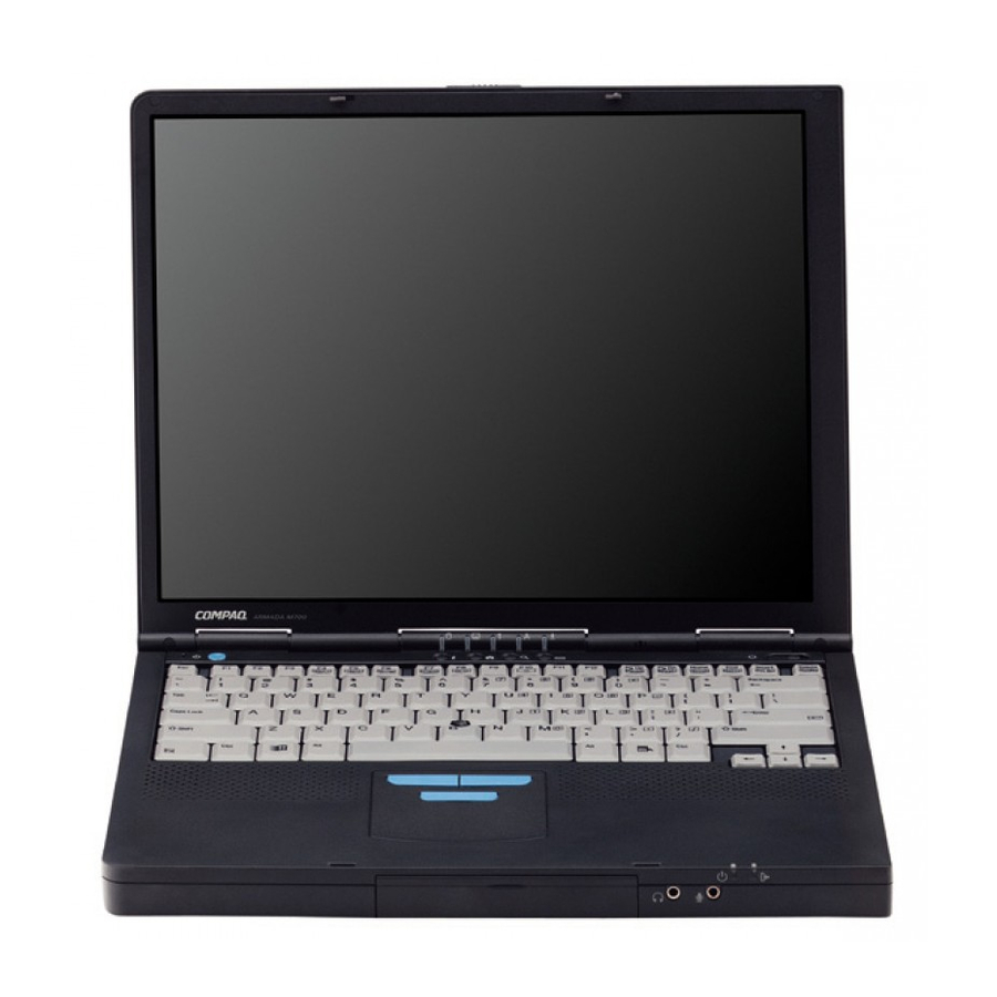
RODUCT ESCRIPTION 1.1 Computer Features and Models The Compaq Armada M700 Series of Personal Computers offers advanced modularity, Intel Pentium III and II processors, and extensive multimedia support. Figure 1-1. Compaq Armada M700 Personal Computer Product Description 1-1... -
Page 11: Models
Models The Armada M700 models are shown in Table 1-1. The computer model designation is composed of a group of characters that define each model’s features. Models and Model Naming Convention Compaq Armada M700 Series of Personal Computers A M 7... - Page 12 Models and Model Naming Convention Compaq Armada M700 Series of Personal Computers 1 2 3 4 5-6 7-9 10 11 12 13-14 15 16 17-19 20-21 22 23 24 A M 7 T 4 X A M 7 T 4 X...
- Page 13 Table 1-2 continued 1 2 3 4 5-6 7-9 10 11 12 13-14 15 16 17-19 20-21 22 23 24 A M 7 P3 650 T 4 X A M 7 P3 650 T 4 X A M 7 P3 650 T 4 X A M 7 P3 650 T 4 X A M 7...
- Page 14 Table 1-2 continued 1 2 3 4 5-6 7-9 10 11 12 13-14 15 16 17-19 20-21 22 23 24 A M 7 P2 400 T 4 X A M 7 P2 400 T 4 X A M 7 P2 400 T 4 X A M 7 P2 400 T 4 X A M 7...
-
Page 15: Features
Features The computer has the following standard features: Intel Pentium III 1-GHz, 900-, 850-, 750-, 700-, 650-, 600- or 450-MHz processors, or Intel Pentium II 400- or 366-MHz processors, depending on computer model 8-MB SDRAM (synchronous graphics) 64-MB of SDRAM (synchronous); expandable to 288 MB 13.3- or 14.1-inch XGA TFT color display;... -
Page 16: Accessing The Web Agent
Configuration Management—optimizes the computer by providing the latest drivers, utilities, and software, which are available on CD-ROM and the Compaq Web site at: www.compaq.com/support/portables NOTE: For further help with Intelligent Manageability, select Start ! Compaq Information Center ! Intelligent Manageability Accessing the Web Agent The computer may have a preinstalled Web Agent that allows computer configuration information to be viewed using Web technology. -
Page 17: Fault Management
Fault Management Fault Management features minimize downtime and data loss by monitoring system performance and generating the following alerts: Hard drive alert—provides 72-hour advance warning of impending hard drive " problems and can automatically start optional backup software. Alerts can be enabled, disabled, and tested, and software can be set to back up information whenever a hard drive alert occurs. -
Page 18: Configuration Management
Configuration Management Configuration Management optimizes software upgrade and customer support procedures. Compaq provides support software to optimize the performance of the computer. This support software is accessible through a monthly CD-ROM subscription. Support software can also be downloaded from the Compaq Web site at: www.compaq.com/support/ portables Managing Power The computer comes with a collection of power management features that allow... -
Page 19: Computer Components
1.2 Computer Components System Memory Options The main memory subsystem supports a minimum standard 32 or 64 megabytes of Synchronous SDRAM, and is expandable to 544 or 576 megabytes, depending on computer model. The minimum standard Synchronous SDRAM is installed on the system board. -
Page 20: Power Equipment
Power Equipment The following power options are available: AC Adapter " Lithium ion battery pack " Automobile Power Adapter/Charger " " Aircraft Power Adapter AC Adapter The AC Adapter is field replaceable and ships with the computer and is available as an option. -
Page 21: Computer External Components
1.3 Computer External Components The computer external components on the front, rear, left side, right side, top, and bottom, of the computer as well as the keyboard components for the pointing stick model and TouchPad model are shown in the following figures and described in the accompanying tables. -
Page 22: Rear Components
Rear Components Figure 1-3 Rear Components Item Component Infrared port Serial connector External monitor connector Docking connector Parallel connector Power connector USB port Keyboard/mouse connector Connects an optional full-sized keyboard or a mouse. Both Table 1-6 Rear Components Function Provides wireless communication between the computer and another infrared-equipped device using an infrared beam. -
Page 23: Left Side Components
Left Side Components Figure 1-4 Left Side Components Item Component Composite TV connector Cable lock connector Airflow vent 1-14 Product Description Table 1-7 Left Side Components Function Connects a television, VCR, camcorder, or overhead projector. Accepts an optional security cable to secure the computer to a fixed object to prevent theft. -
Page 24: Right Side Components
Right Side Components Figure 1-5 Right Side Components Right Side Components Item Component PC Card slots Airflow vent MultiBay Audio bass port RJ-11 jack RJ-45 jack Table 1-8 Function Accepts 16- and 32-bit CardBus PC Cards. Allows airflow needed to cool computer components. Do not block airflow vents. -
Page 25: Top Components
Top Components Figure 1-6 Top Components 1-16 Product Description... - Page 26 Item Component/Icon Display switch Suspend button* Hard drive light MultiBay drive light Num Lock light Caps Lock light Scroll Lock light Power switch Internal speakers *In Windows 98 the term sleep button replaces the term suspend button. **In Windows 98 the term Standby replaces the term Suspend. Table 1-9 Top Components Function...
-
Page 27: Bottom Components
Bottom Components Figure 1-7 Bottom Components Item Component Battery bay Hard drive security screw Modem slot cover MultiBay notch MultiBay release latch Label 1-18 Product Description Table 1-10 Bottom Components Function Holds the primary battery. Secures the hard drive in the hard drive bay. Contains the mini PCI modem card. -
Page 28: Easypoint Iv Pointing Stick Model Components
EasyPoint IV Pointing Stick Model Components Figure 1-8 EasyPoint IV Pointing Stick Model Components Item Component EasyPoint IV pointing stick Left pick button Scroll button Right pick button Table 1-11 Keyboard Components Pointing Stick Model Function Moves the cursor in the direction of finger movement. Functions like the left button on an external mouse. -
Page 29: Touchpad Components
TouchPad Components Figure 1-9 TouchPad Components Item Component TouchPad Left TouchPad button Right TouchPad button 1-20 Product Description Table 1-12 Keyboard Components TouchPad Model Function Moves the cursor in the direction of finger movement. Functions like the left button on an external mouse. Functions like a right button on an external mouse. -
Page 30: Design Overview
1.4 Design Overview This section presents a design overview of key parts and features of the computer. For assembly/disassembly instructions for the parts described in this section, refer to Chapter 5. System Board The system board provides the following device connections: Memory expansion board "... - Page 31 1-22 Product Description...
-
Page 32: Troubleshooting
chapter ROUBLESHOOTING Follow these basic steps when beginning the troubleshooting process: 1. Complete the preliminary steps listed in Section 2.1. 2. Run the Power-On Self-Test (POST) as described in Section 2.3. 3. Run Computer Setup as described in Section 2.5. 4. -
Page 33: Preliminary Steps
2.1 Preliminary Steps IMPORTANT: Use AC power when running POST or Computer Setup. A low battery condition could initiate Hibernation and interrupt the test. Before running POST, complete the following steps: 1. Obtain established passwords. If you must clear the passwords, go to Section 2.2. 2. -
Page 34: Clearing Passwords
2.2 Clearing Passwords 1. Turn off the computer. 2. Disconnect the AC Adapter (refer to Section 5.3). 3. Remove the battery pack (Section 5.6). 4. Disconnect and remove the Real Time Clock (RTC) battery (Section 5.11). 5. Wait five minutes. 6. -
Page 35: Post Error Messages
2.4 POST Error Messages If the system is not functioning well enough to run POST, or if the display is not functioning well enough to show POST error messages, refer to the Troubleshooting tables in Section 2.6. If POST detects an error, one of the following events occurs: A message with the prefix "WARNING"... - Page 36 Message Description CMOS checksum invalid, run CMOS RAM information has been corrupted. CMOS failure, run SCU CMOS RAM has lost power. Diskette controller error The diskette drive controller failed to respond to the recalibrate command. Diskette track 0 failed The diskette drive cannot read track 0 of the diskette in the drive.
- Page 37 Fatal errors emit a beep and may display a FATAL message. Fatal errors indicate severe problems, such as a hardware failure. Fatal errors do not allow the system to resume. Some of the Fatal error beep codes are listed at the end of this section. Message CMOS RAM test failed DMA controller faulty...
-
Page 38: Compaq Utilities
2.5 Compaq Utilities Compaq Utilities contain several functions that Determine if various computer devices are recognized by the system and are operating properly. Provide information about the system once it is configured. Compaq Utilities include the following programs: Computer Setup Compaq Diagnostics To access Compaq Utilities: 1. -
Page 39: Using Computer Setup
Using Computer Setup All information and settings in Computer Setup are accessed from the File, Security, or Advanced menus. NOTE: Your settings in Computer Setup are not affected by updating the system ROM. To view information or change a setting in Computer Setup: 1. -
Page 40: Security Menu
Security Menu Begin here Setup password Power-On password Password options DriveLock passwords Device security System IDs To do this Enter, change, or delete a setup password. Enter, change, or delete a power-on password. Enable/disable: QuickLock/QuickBlank. Lock keyboard and pointing stick or touchpad at startup. -
Page 41: Advanced Menu
Advanced Menu Begin here Language (or press Boot Options Device Options 2-10 Troubleshooting To do this Change the Computer Setup language. Enable/disable QuickBoot, which starts the computer more quickly by eliminating some startup tests. (If you suspect a memory failure and want to test memory automatically during startup, you may want to disable QuickBoot.) MultiBoot, which enables you to set a... -
Page 42: Using Compaq Diagnostics For Windows
Using Compaq Diagnostics for Windows 1. Access Compaq Diagnostics for Windows by selecting Start!Settings!Control Panel!Compaq Diagnostics. 2. To select a category, choose one of two methods: Select the Categories menu, then select a category from the drop-down list. Select a category icon on the toolbar. 3. - Page 43 Serial port Infrared port Parallel port Ethernet port Low Battery Warning Beep External Energy Saving Monitor Connected Power Management Enabled Conservation Level Level Definition High Medium Custom Enable QuickLock/QuickBlank Enable Power-On Password Disable Serial/Infrared Ports Disable Parallel Port Disable PC Card Slots Setup Password Power-On Password Diskette Drives...
-
Page 44: Troubleshooting Without Diagnostics
2.6 Troubleshooting Without Diagnostics This section provides information about how to identify and correct some common hardware, memory, and software problems. It also explains several types of messages that may be displayed on the screen. Since symptoms can appear to be similar, carefully match the symptoms of the computer malfunction against the problem description in the Troubleshooting tables to avoid a misdiagnosis. -
Page 45: Checklist For Solving Problems
Checklist for Solving Problems If you encounter a minor problem with the computer or software applications, go through the following checklist for possible solutions: Is the computer connected to an external power source, or does it have a fully charged battery pack installed? Are all cables connected properly and securely? Did the diskette drive contain a nonbootable diskette when you turned on the computer? - Page 46 Problem Possible Cause Computer does not beep System beeps have been after the Power-On Self- turned down. Test (POST). Internal speaker does not Volume may be turned off or produce sound when an set too low. external audio source is connected to the stereo line-jack.
- Page 47 Problem Computer is beeping and battery power light is blinking Computer battery charge light blinks to indicate low battery condition, but computer does not beep. Battery pack will not charge. Battery pack was exposed Computer shut down and memory was lost when replacing the battery pack.
- Page 48 Solving Compact Disc and DVD-ROM Problems Problem Possible Cause Drive cannot read a disc Disc is not properly seated in the drive. Disc is loaded in the loading tray upside down. Disc has a scratch on its surface. CD-ROM drive or DVD- Drive is not connected ROM drive is not detected properly.
- Page 49 Problem Accessing information on the hard drive is much slower than usual. Hard drive does not work. Hard drive is not seated Errors occur after starting from an additional hard drive. System does not recognize a hard drive. DriveLock settings cannot be accessed in Computer Setup.
- Page 50 Table 2-13 continued Problem Possible Cause Cannot communicate There is a conflict with the # with another computer bits. (continued). There is a stop byte conflict. There is a parity conflict. Cannot transmit data. Direct sunlight, fluorescent light, or flashing incandescent light is close to the infrared connections.
- Page 51 Problem Modem loses connection. Modem not responding Modem does not dial correctly. Characters are garbled/transfer rates are slow. 2-20 Troubleshooting Table 2-15 Solving Modem Problems Possible Cause Solution The cable connection from Check to make sure the telephone the phone line to the modem cable is properly connected.
- Page 52 Table 2-15 Continued Problem Possible Cause Phone line noise causing Hang-up Delay S Register a disconnection. (S10) set too low. No dial tone Phone service is not connected to the telephone wall jack. The modem is not responding to commands from the computer keyboard.
- Page 53 Table 2-15 Continued Problem Modem does not connect at highest speed. 2-22 Troubleshooting Possible Cause Solution Line conditions in your area Have your telephone line checked or in the area you are calling by your local telephone service may not support the highest provider.
- Page 54 Solving PC Card Problems Problem Possible Cause Computer does not PC Card is not inserted beep when a PC Card properly. is inserted. Speakers are turned off or volume is turned down. PC Card or card driver is not PCMCIA compliant. Computer beeps only The computer beeps once to once when a PC Card is...
- Page 55 Problem Computer will not turn on. Computer turned off while it was left unattended. Problem Characters on computer display are dim. Computer screen is blank and external monitor displays information. Fn+F4 hotkey combination does not switch between internal and external displays.
- Page 56 Solving USB Problems Problem Possible Cause External device connected The operating system limits to a USB connector does external devices connected not work. by USB to two tiers which can include no more than two hubs on the first tier and no more than one keyboard and one pointing device on the first or second tier.
- Page 57 2-26 Troubleshooting...
-
Page 58: Illustrated Parts Catalog
LLUSTRATED ARTS This chapter provides an illustrated parts breakdown and a reference for spare part numbers and option part numbers for the Compaq Armada M700 Series of Personal Computers. 3.1 Serial Number Location When ordering parts or requesting information, provide the computer serial number and model number located on the bottom of the computer (Figure 3-1). -
Page 59: Computer System Major Components
3.2 Computer System Major Components Figure 3-2. Computer System Major Components 3-2 Illustrated Parts Catalog... - Page 60 Spare Parts: Computer System Major Components Item Description Display assembly 14.1-inch, XGA, CTFT 13.3-inch, XGA, CTFT Touch button with TouchPad Touch button Top cover includes LED board and Internet buttons; used with the following SKUs: 470011-XXX 215198-XXX 206645-XXX 206646-XXX includes LED board; used with the following SKUs: 205857-XXX 205858-XXX 205860-XXX...
- Page 61 Computer System Major Components (continued) 3-4 Illustrated Parts Catalog...
- Page 62 Table 3-1 continued Item Description Cable Kit, includes: RAM board Real time clock (RTC) battery Infrared board (includes RJ-11 and RJ-45 jacks) Voltage converter board used with the following SKUs: 470011-XXX 215199-XXX 215191-XXX 215197-XXX used with the following SKUs: 139114-XXX 140141-XXX 139116-XX2 140142-XXX...
- Page 63 Computer System Major Components (continued) 3-6 Illustrated Parts Catalog...
- Page 64 Table 3-1 continued Item Description System board (continued; includes processor assembly) supports Intel Mobile Pentium III 450-MHz with MMX technology; used with the following SKUs: 139117-XXX 139120-XXX 159696-XXX 159697-XXX supports Intel Mobile Pentium II 400-MHz with MMX technology; used with the following SKUs: 124939-XX2 124940-XX4 400322-XX6...
-
Page 65: Plastics Kit Components
3.3 Plastics Kit Components Figure 3-3. Plastics Kit Components 3-8 Illustrated Parts Catalog... - Page 66 Plastics Kit Components Spare Part Number 135230-001 Item Description Switch cover without Easy Access buttons; used with the following SKUs: 124898-XXX 124899-XXX 124938-XXX 124939-XXX 124940-XXX 124941-XXX 139114-XXX 139116-XXX 139117-XXX 139120-XXX 140141-XXX 140142-XXX 149207-XXX Switch cover with Easy Access buttons; used with the following SKUs: 470011-XXX 206645-XXX 206646-XXX...
-
Page 67: Cable Kit Components
3.4 Cable Kit Components Figure 3-4. Cable Kit Components Item Description RAM board Real time clock (RTC) battery not illustrated: microphone assembly microphone cable speaker cable 3-10 Illustrated Parts Catalog Table 3-3 Cable Kit Components Spare Part Number 152605-001... -
Page 68: Mass Storage Devices
3.5 Mass Storage Devices Figure 3-5. Mass Storage Devices Spare Parts: Mass Storage Devices Item Description Hard drive 30.0 GB 20.0 GB 18.0 GB 12.0 GB 10.0 GB 6.4 GB 6.0 GB; used only with SKUs 205857-XXX and 205858-XXX 24-speed Max CD-ROM drive 20-speed Max CD-RW drive (not illustrated) 8-speed Max DVD-ROM drive 4-speed Max DVD-ROM drive... -
Page 69: Miscellaneous
3.6 Miscellaneous Spare Parts: Miscellaneous (not illustrated) Description Armada M700 Maintenance & Service Guide Battery Charger Cables Automobile Power Adapter/Charger cable Aircraft Power Adapter cable Composite TV cable RJ11 modem cable RJ45 modem cable Hard Drive Adapter Logo Kit Memory expansion board... -
Page 70: Removal And Replacement Preliminaries
chapter EMOVAL AND RELIMINARIES This chapter provides essential information for proper and safe removal and replacement service. 4.1 Tools Required You will need the following tools to complete the removal and replacement procedures: Magnetic Torx T-8 screwdriver (for all screws unless otherwise specified) 9/32-inch socket for bushing guides 4.2 Service Considerations Listed below are some of the considerations that you should keep in mind during... -
Page 71: Cables And Connectors
Cables and Connectors Cables must be handled with extreme care to avoid damage. Apply only the tension required to unseat or seat the cables during removal and insertion. Handle cables by the connector whenever possible. In all cases, avoid bending, twisting, or tearing cables. Ensure that cables are routed in such a way that they cannot be caught or snagged by parts being removed or replaced. -
Page 72: Preventing Electrostatic Damage
4.4 Preventing Electrostatic Damage Many electronic components are sensitive to electrostatic discharge (ESD). Circuitry design and structure determine the degree of sensitivity. Networks built into many integrated circuits provide some protection, but in many cases the discharge contains enough power to alter device parameters or melt silicon junctions. A sudden discharge of static electricity from a finger or other conductor can destroy static-sensitive devices or microcircuitry. -
Page 73: Workstation Precautions
Workstation Precautions Use the following grounding precautions at workstations: Cover the workstation with approved static-dissipative material (refer to Table 4-2 later in this chapter). Use a wrist strap connected to a properly grounded work surface and use properly grounded tools and equipment. Use field service tools, such as cutters, screwdrivers, and vacuums that are conductive. -
Page 74: Grounding Equipment And Methods
Grounding Equipment and Methods Grounding equipment must include either a wrist strap or a foot strap at a grounded workstation. When seated, wear a wrist strap connected to a grounded system. Wrist straps are flexible straps with a minimum of one megohm ±10% resistance in the ground cords. To provide proper ground, a strap must be worn snug against the skin. -
Page 75: Electrostatic Voltage Levels And Protective Materials
Electrostatic Voltage Levels and Protective Materials Table 4-1 shows how humidity affects the electrostatic voltage levels generated by different activities. Event Walking across carpet Walking across vinyl floor Motions of bench worker Removing DIPS from plastic tube Removing DIPS from vinyl tray Removing DIPS from Styrofoam Removing bubble pack from PCB Packing PCBs in foam-lined box... -
Page 76: Removal And Replacement Procedures
chapter EMOVAL AND ROCEDURES 5.1 Serial Number The computer serial number should be reported to Compaq when requesting information or ordering spare parts. The serial number is located on the bottom of the computer. Figure 5-1. Serial Number Location EPLACEMENT Removal and Replacement Procedures 5-1... -
Page 77: Disassembly Sequence Chart
5.2 Disassembly Sequence Chart Use the chart below to determine the section number to be referenced when removing the components from the computer. 5.3 Disconnecting the Computer 5.4 Computer Feet 5.5 Preparing the Computer for Disassembly 5.6 Battery Packs Removing a Battery Pack Inserting a Battery Pack 5.7 Hard Drives Removing a Hard Drive... -
Page 78: Disconnecting The Computer
5.3 Disconnecting the Computer 1. Shut down the computer. 2. Close the computer. 3. Position the computer so the rear panel faces forward. 4. Disconnect the power cord from the AC Adapter ! (Figure 5-3). 5. Disconnect the power cord from the wall outlet ". 6. -
Page 79: Computer Feet
5.4 Computer Feet The computer feet are oval, adhesive-backed rubber pads. The computer feet are included in the Miscellaneous Plastic Spare Kit. Install the feet by removing the protective covering from the adhesive back an attaching the feet to the bottom of the computer (Figure 5-4). NOTE: The front left computer foot adheres to the bottom of the battery pack. -
Page 80: Preparing The Computer For Disassembly
5.5 Preparing the Computer for Disassembly 1. Shut down the computer. 2. Disconnect the AC Adapter and all external devices connected to the computer. 3. Remove the battery pack from the battery bay (Section 5.6). CAUTION: Failure to disconnect the AC Adapter from the computer and remove the battery pack before removing and installing internal components can damage the equipment. -
Page 81: Battery Packs
5.6 Battery Packs WARNING: To reduce the risk of injury or damage to the battery pack, do not crush, puncture, or incinerate the battery pack or short the metal contacts. Do not attempt to open or service the battery pack. Removing a Primary Battery Pack from the Battery Bay 1. -
Page 82: Inserting A Primary Battery Pack In The Battery Bay
Inserting a Primary Battery Pack in the Battery Bay CAUTION: To prevent damage to the computer, do not insert a battery pack until the computer is fully reassembled. 1. Close the computer. 2. Tilt the computer up – (Figure 5-6). 3. -
Page 83: Hard Drives
5.7 Hard Drives Removing a Hard Drive from the Hard Drive Bay Before removing a hard drive, back up all information on the hard drive. 1. Save all work, exit all applications, and shut down the computer. 2. Tilt the computer at an angle – so the bottom of the computer is accessible (Figure 5-7). - Page 84 4. Push down on the hard drive bezel on the front of the hard drive – (Figure 5-8). 5. Lift the bezel up 90 degrees to create a handle —. Pull the hard drive out of the hard drive bay. Figure 5-8.
-
Page 85: Inserting A Hard Drive Into The Hard Drive Bay
Inserting a Hard Drive into the Hard Drive Bay 1. With the hard drive bezel pulled down, slide the hard drive into the hard drive bay – until the drive is seated (Figure 5-9). 2. Push up on the hard drive bezel to secure the hard drive in the bay —. Figure 5-9. -
Page 86: Multibay Devices
5.8 MultiBay Devices Removing MultiBay Devices 1. Save all work, exit all applications, and shut down the computer. 2. Remove the media (diskette, CD-ROM, DVD-ROM) from the drive. Be sure the drive tray is closed. 3. Tilt the computer at an angle – so the bottom of the computer is accessible (Figure 5-10). -
Page 87: Inserting Multibay Devices
Inserting MultiBay Devices 1. Remove the media (diskette, CD-ROM, etc.) from the drive to be inserted into the MultiBay. Ensure that the CD tray is closed. 2. With the bezel facing out, slide the device into the MultiBay until it clicks into place (Figure 5-11). -
Page 88: Inserting A Hard Drive Into The Multibay Adapter
Inserting a Hard Drive into the MultiBay Adapter Before a hard drive can inserted into the MultiBay, it must first be placed in the hard drive MultiBay adapter. 1. Push the adapter slide tabs – toward the outside of the adapter (Figure 5-12). 2. -
Page 89: Pc Cards
5.9 PC Cards The procedure for removing PC Cards varies with the operating system being used and with the kind of PC Card being removed. If Windows 95 or Windows 98 is running: A PC Card can be removed while the computer is on or off. The PC Card icon appears in the system tray on the Windows taskbar only while a PC Card is inserted. -
Page 90: Removing A Pc Card
Removing a PC Card If you are running Windows 95 or Windows 98, you do not need to turn off the computer or initiate Suspend before removing a PC Card. CAUTION: If you are running Windows 95 or Windows 98, you should always stop PC Cards before removing them to prevent damage to the PC Card or computer. -
Page 91: Inserting A Pc Card
Inserting a PC Card 1. Save all work, exit all applications, and turn off the computer. 2. Open the PC Card door by flipping it down (Figure 5-14). 3. Align the edges of the PC Card with the rails on the sides of one of the PC Card slots. -
Page 92: Modem/Combo Card
5.10 Modem/Combo Card The computer can be equipped with a modem card, a network interface card (NIC), or a combination modem/NIC (modem/combo) card. 1. Prepare the computer for disassembly (Section 5.5). 2. Turn the computer bottom side up with the rear panel facing forward. 3. - Page 93 5. Lift the left side of the modem/combo card to disconnect it from the system board. Swing the card to the right – (Figure 5-16). 6. Disconnect the LAN and modem connectors from the card —. Figure 5-16. Removing a Modem/Combo Card Reverse the above procedure to install the modem/combo card and its cover.
-
Page 94: Rtc Battery
5.11 RTC Battery 1. Save all work, exit all applications, and shut down the computer. 2. Remove the modem/combo card cover and the modem/combo card (Section 5.10). 3. Disconnect the RTC battery cable from the system board – (Figure 5-17). 4. -
Page 95: Keyboard
5.12 Keyboard WARNING: Failure to unplug the power cord and remove the battery pack before installing a memory expansion board can damage the equipment and expose you to the risk of electrical shock. CAUTION: Electrostatic discharge (ESD) can damage electronic components. Before beginning this procedure, ensure that you are properly grounded. - Page 96 5. Release the Zero Insertion Force (ZIF) connector to which the keyboard cable is connected – (Figure 5-19). 6. Disconnect the keyboard cable from the connector on the system board —. 7. Release the ZIF connector to which the pointing device cable is connected ˜ (EasyPoint IV models only).
-
Page 97: Memory Expansion
5.13 Memory Expansion The memory compartment is located underneath the keyboard and contains two memory slots. The computer standard memory is contained in one slot. Computer memory can be expanded by installing a memory board in the empty slot and/or replacing the standard memory board. -
Page 98: Installing A Memory Expansion Board
Installing a Memory Expansion Board All memory expansion boards supported by the computer can be used in either of the two memory expansion slots. The memory expansion boards are also all keyed (notched) to ensure correct positioning. 1. Insert the memory expansion board into an empty memory expansion slot at a –... -
Page 99: Switch Cover
5.14 Switch Cover 1. Prepare the computer for disassembly (Section 5.5). 2. Remove the keyboard (Section 5.12). 3. Position the computer so the rear panel faces forward. 4. Remove the two screws from the rear panel of the computer that secure the switch cover to the base assembly (Figure 5-22). - Page 100 7. Lift the switch cover straight up (Figure 5-23). Figure 5-23. Removing the Switch Cover Reverse the above procedure to install the switch cover. Removal and Replacement Procedures 5-25...
-
Page 101: Display Assembly
5.15 Display Assembly NOTE: To prevent the computer from tipping over during removal of the display assembly, a MultiBay device can be inserted into the computer MultiBay. 1. Prepare the computer for disassembly (Section 5.5). 2. Remove the keyboard (Section 5.12). 3. - Page 102 7. Position the computer so the rear panel faces forward. 8. Remove the two screws that secure the display assembly to the base assembly (Figure 5-25). Figure 5-25. Removing the Display Assembly Screws Removal and Replacement Procedures 5-27...
- Page 103 9. Lift the display assembly straight up (Figure 5-26). Figure 5-26. Removing the Display Assembly Reverse the above procedure to install the display assembly. 5-28 Removal and Replacement Procedures...
-
Page 104: Top Cover
5.16 Top Cover 1. Prepare the computer for disassembly (Section 5.5). 2. Remove the keyboard (Section 5.12). 3. Remove the switch cover (Section 5.14). 4. Remove the display assembly (Section 5.15). 5. Turn the computer bottom side up with the front of the computer facing forward. 6. - Page 105 8. Remove the four screws securing the top cover to the computer base (Figure 5-28). Figure 5-28. Removing the Top Cover Screws 5-30 Removal and Replacement Procedures...
- Page 106 9. Disconnect the pointing device button cable – (Figure 5-29). 10. Disconnect the right — and left ˜ speaker cables. 11. Partially lift the top cover. 12. Disconnect the LED board cable ™. 13. Remove the top cover. Figure 5-29. Removing the Top Cover Reverse the above procedures to install the top cover.
- Page 107 The top cover must be removed before the LED board can be removed. 1. Remove the two screws – securing the LED board to the top cover (Figure 5-30). 2. Remove the LED board from the top cover —. Figure 5-30. Removing the LED Board Reverse the above procedures to install the LED board.
-
Page 108: Usb Board
5.17 USB Board 1. Prepare the computer for disassembly (Section 5.5). 2. Remove the keyboard (Section 5.12). 3. Remove the switch cover (Section 5.14). 4. Remove the display assembly (Section 5.15). 5. Remove the top cover (Section 5.16). 6. Position the computer so the rear panel faces forward. 7. -
Page 109: Voltage Converter Board
5.18 Voltage Converter Board 1. Prepare the computer for disassembly (Section 5.5). 2. Remove the keyboard (Section 5.12). 3. Remove the switch cover (Section 5.14). 4. Remove the display assembly (Section 5.15). 5. Remove the top cover (Section 5.16). 6. Lift up on the front and right side of the voltage converter board to disconnect it from the system board (Figure 5-32). -
Page 110: Infrared Board
5.19 Infrared Board 1. Prepare the computer for disassembly (Section 5.5). 2. Remove the keyboard (Section 5.12). 3. Remove the switch cover (Section 5.14). 4. Remove the display assembly (Section 5.15). 5. Remove the top cover (Section 5.16). 6. Remove the screw that secures the infrared board to the base assembly – (Figure 5-33). -
Page 111: System Board
5.20 System Board 1. Prepare the computer for disassembly (Section 5.5). 2. Remove the modem/combo card (Section 5.10). 3. Remove the RTC battery (Section 5.11). 4. Remove the keyboard (Section 5.12). 5. Remove the switch cover (Section 5.14). 6. Remove the display assembly (Section 5.15). 7. - Page 112 13. Disconnect the memory bracket/connector by lifting up on the left side – (Figure 5-35). 14. Remove the screw underneath the memory bracket/connector that secures the system board to the base assembly —. 15. Remove the two screws that secure the system board to the base assembly ˜. Figure 5-35.
- Page 113 16. Remove the two screws that secure the PC Card assembly to the base assembly (Figure 5-36). Figure 5-36. Removing the PC Card Assembly Screws 5-38 Removal and Replacement Procedures...
- Page 114 17. Lift straight up on the system board to remove it from the base assembly (Figure 5-37). Figure 5-37. Removing the System Board Reverse the above procedure to install the system board. Removal and Replacement Procedures 5-39...
-
Page 115: Fan
5.21 Fan 1. Prepare the computer for disassembly (Section 5.5). 2. Remove the modem/combo card (Section 5.10). 3. Remove the RTC battery (Section 5.11). 4. Remove the keyboard (Section 5.12). 5. Remove the switch cover (Section 5.14). 6. Remove the display assembly (Section 5.15). 7. - Page 116 12. Remove the screw – that secures the fan to the system board (Figure 5-39). 13. Remove the fan —. Figure 5-39. Removing the Fan Reverse the above procedure to install the fan to the system board. Removal and Replacement Procedures 5-41...
- Page 117 5-42 Removal and Replacement Procedures...
-
Page 118: Specifications
chapter PECIFICATIONS 6.1 Physical and Environmental Dimensions Height Depth Width Weight (depends on configuration) Standalone (Battery) Power Requirements Nominal operating voltage Average operating power Peak operating power AC Adapter Power Requirements Operating voltage Operating current Operating frequency range Maximum output voltage Maximum transient Temperature Operating... -
Page 119: Display
6.2 Displays Dimensions Height Width Diagonal Number of Colors Contrast Ratio Brightness Pixel Resolution Pitch Format Configuration Backlight Character Display Total Power Consumption Dimensions Height Width Diagonal Number of Colors Contrast Ratio Brightness Pixel Resolution Pitch Format Configuration Backlight Character Display Total Power Consumption 6-2 Specifications Table 6-2... -
Page 120: Hard Drive
6.3 Hard Drives 6.4 GB User capacity per 6.4 GB drive Form factor 2.5 inches Drive height (with drive frame, in mm) Drive width (with drive frame, in mm) Interface type ATA-4 Seek times (typical read, including settling) Single track 2.5 ms Average 12.0 ms... -
Page 121: Diskette Drive
6.4 Diskette Drive Diskette Size High Density Low Density Light Height Bytes per Sector Sectors per Track Hight Density Low Density Tracks per Side High Density Low Density Read/Write Heads Average Seek Times Track-to-Track (high/low) Average (high/low) Settling Time Latency Average 6-4 Specifications Table 6-5 Diskette Drive... -
Page 122: Cd-Rom Drive
6.5 CD-ROM Drive Applicable Disc Center Hole Diameter Disc Diameter Disc Thickness Track Pitch Laser Beam Divergence Output Power Type Wave Length Access Time Random Full Stroke Audio Output Level Line Out Headphone Cache Buffer Data Transfer Rate Sustained, 24X Variable Normal PIO Mode 4 (single burst) Startup time... -
Page 123: Dvd-Rom Drive
6.6 DVD-ROM Drive Applicable Disc Center Hole Diameter Disc Diameter Disc Thickness Track Pitch Capacity DVD-5 DVD-9 DVD-10 Mode 1, 12 Mode 2, 12 cm 8 cm Laser Output Power Type Wave Length Access Time Random Full Stroke Audio Output Level Line Out Headphone Cache Buffer... -
Page 124: Drive
6.7 LS-120 Drive 1.68 MB DMF 1.44 MB 1,720,320 Formatted capacity (bytes) Sector size (bytes) 3,360 Sectors Magnetic tracks surface Optical servo tracks/surface Sectors/track Sector interleave Spare sectors Zones (each side) Average random seek 70 ms Track-to-track seek 25 ms Max single seek 170 ms Average latency... -
Page 125: Battery Pack
6.8 Battery Pack Dimensions Height Length Weight Weight Energy Voltage Amp-hour capacity Watt-hour capacity Environmental Requirements Operating Temperatures Charging Temperatures Recommended Storage Temperatures No longer than 1 month No longer than 3 months No longer than 1 year 6.9 System DMA Hardware DMA DMA0 DMA1... -
Page 126: System Interrupts
6.10 System Interrupts Hardware IRQ IRQ0 IRQ1 IRQ2 IRQ3 IRQ4 IRQ5 IRQ6 IRQ7 IRQ8 IRQ9 IRQ10 IRQ11 IRQ12 IRQ13 IRQ14 IRQ15 NOTE: PC Cards may assert IRQ3, IRQ4, IRQ5, IRQ7, IRQ9, IRQ10, IRQ11, or IRQ15. Either the infrared or the serial port may assert IRQ3 or IRQ4. * Default configuration;... -
Page 127: System I/O Addresses
6.11 System I/O Addresses I/O Address (Hex) 000 - 00F 010 - 01F 020 - 021 022 - 024 025 - 03F 02E - 02F 040 - 043 044 - 05F 062 - 063 065 - 06F 070 - 071 072 - 07F 080 - 08F 090 - 091... - Page 128 Table 6-12 continued I/O Address (Hex) 202 - 21F 220 - 22F 230 - 26D 26E - 26 278 - 27F 280 - 2AB 2A0 - 2A7 2A8 - 2E7 2E8 - 2EF 2F0 - 2F7 2F8 - 2FF 300 - 31F 320 - 36F 370 - 377 378 - 37F...
-
Page 129: System Memory Map
6.12 System Memory Map Size Memory Address 640 K 00000000 - 0009FFFF 128 K 000A0000 - 000BFFFF 48 K 000C0000 - 000CBFFF 160 K 000C8000 - 000E7FFF 64 K 000E8000 - 000FFFFF 15 M 00100000 - 00FFFFFF 58 M 01000000 - 047FFFFF 58 M 04800000 - 07FFFFFF 08000000 - 080FFFFF... -
Page 130: Appendix A C P A
appendix ONNECTOR Connector Signal Carrier Detect Receive Data Transmit Data Data Terminal Ready Ground Connector SSIGNMENTS Table A-1 RJ-11 Signal NC_J3A NC_J3B RING NC_J3C NC_J3D Unused Unused Table A-2 Serial Connector Signal Data Set Ready Ready to Send Clear to Send Ring Indicator Table A-3 Microphone Jack... - Page 131 Connector Connector Signal Strobe Data Bit 0 Data Bit 1 Data Bit 2 Data Bit 3 Data Bit 4 Data Bit 5 Data Bit 6 Data Bit 7 Acknowledge Busy Paper End Select A-2 Connector Pin Assignments Table A-4 Stereo Speaker/Headphone Jack Signal Audio out Ground...
- Page 132 Docking Connector Signal EBOXL AGND EBOXS1 AGND GREEN AGRD BLUE AGND VSYNC HSYNC DDC DAT DDC CLK INDEX RDATA TRK0 WDATA WGATE STEP POWER ON SYS RESET DSKCHG +5 V (VDD) AUGND XA2/L IN XA3/R IN MID0/MIC IN AUGND XA0/L OUT XSD/MIC SN Table A-7 Signal...
- Page 133 Table A-7 Continued Signal PDATA6 LD14 PDATA7 LD15 ERROR LCLK RXD1 LVREQ TXD1 LCREQ RTS1 LEN CTS1 LIIC CLK DTR1 LIIC DAT DSR1 EX DCD1 EX 12C DATA 12C CLK HDSEL WPROT EBOXS2 /GND ERDY EBOXL /GND FLUSHREQ MEMACK PS2 VCC SERIRQ PS2 CLK EXPREQ...
- Page 134 Table A-7 Continued Signal VBATT AD[23] AD[21] AD[19] AD[17] AD[14] AD[12] AD[10] AD[08] AD[07] AD[05] AD[03] AD[01] External Keyboard/Mouse Connector Connector Signal CBE3 CBE2 IRDY DEVSEL LOCK OERR SERR RSVD3 M 12C CLK M 12C DATA M RING MGND M DXTN M DXTP MSTRBAT Table A-8...
- Page 135 Signal Red Analog Green Analog Blue Analog Ground Ground Ground Ground A-6 Connector Pin Assignments Table A-9 External Monitor Connector Signal Ground DDC Data Horizontal Sync Vertical Sync DDC Clock...
-
Page 136: Power Cord Set Requirements
OWER 3-Conductor Power Cord Set The wide range input feature of the Compaq Armada M700 Series of Personal Computers permits it to operate from any line voltage from 100 to 120 or 220 to 240 volts AC. The power cord set received with the computer meets the requirements for use in the country where the equipment is purchased. -
Page 137: Country-Specific Requirements
Country-Specific Requirements 3-Conductor Power Cord Set Requirements—By Country Country Australia Austria Belgium Canada Denmark Finland France Germany Italy Japan The Netherlands Norway Sweden Switzerland United Kingdom United States Notes 1. The flexible cord must be <HAR> Type HO5VV-F, 3-conductor, 1.0 mm conductor size. -
Page 138: Index
Index AC Adapter, spare part number, 3-7 Aircraft Power Adapter, 1-11 cable spare part number, 3-12 airflow vent, illustrated, 1-14, 1-15 Asset Management, 1-7 asset tag number, 1-7 audio bass port, illustrated, 1-15 Automobile Power Adapter/Charger, 1-11 cable spare part number, 3-12 battery bay, illustrated, 1-18 battery charge light, illustrated, 1-12... - Page 139 grounding methods, 4-5 hard drive illustrated, 1-12 bezel, 5-9 illustrated, 3-2, 3-11 inserting into hard drive bay, 5-10 inserting into MultiBay adapter, 5-13 light, illustrated, 1-17 removing from hard drive bay, 5-8 security screw, illustrated, 1-18 spare part number, 3-7, 3-11 hardware updating, 2-13 headphone jack illustrated, 1-12...
- Page 140 packaging precautions, 4-3 parallel connector illustrated, 1-13 pinout, A-2 password clearing, 2-3 PC Card, 5-14 inserting, 5-16 removing, 5-15 slots, illustrated, 1-15 pick button, illustrated, 1-19 plastic parts, handling, 4-1 Plastics Kit components illustrated, 3-8 components, illustrated, 3-2 spare part number, 3-3, 3-9 pointing device caps spare part number, 3-12 ports, default settings, 2-12...
- Page 141 universal serial bus (USB) board illustrated, 3-2 removal, 5-33 spare part number, 3-3 port illustrated, 1-13 board removal, 5-33 utilities, Compaq, 2-7 I-4 Index voltage converter board illustrated, 3-2 removal, 5-34 spare part number, 3-5 warning messages, 2-5 web agent, 1-7 workstation precautions, 4-4...
Need help?
Do you have a question about the Armada M700 Series and is the answer not in the manual?
Questions and answers