Compaq Armada M700 Series Reference Manual
Hp armada m700: reference guide
Hide thumbs
Also See for Armada M700 Series:
- Reference manual (156 pages) ,
- Maintenance and service manual (141 pages) ,
- Quickspecs (24 pages)
Table of Contents
Advertisement
Quick Links
Notice
The information in this guide is subject to change without notice.
COMPAQ COMPUTER CORPORATION SHALL NOT BE LIABLE FOR
TECHNICAL OR EDITORIAL ERRORS OR OMISSIONS CONTAINED
HEREIN; NOR FOR INCIDENTAL OR CONSEQUENTIAL DAMAGES
RESULTING FROM THE FURNISHING, PERFORMANCE, OR USE OF
THIS MATERIAL.
This guide contains information protected by copyright. No part of this
guide may be photocopied or reproduced in any form without prior
written consent from Compaq Computer Corporation.
© 2000 Compaq Computer Corporation.
Printed in U.S.A., U.K., Singapore, and Taiwan.
COMPAQ, the Compaq logo, Armada, and ROMPaq Registered in the
U.S. Patent and Trademark Office.
Microsoft, Windows, and Windows NT are trademarks or registered
trademarks of Microsoft Corporation.
Intel and Pentium are registered trademarks, and SpeedStep is a
trademark of Intel Corporation.
Phoenix is a registered trademark and MultiBoot is a trademark of
Phoenix Technologies Ltd.
Imation and SuperDisk are trademarks of Imation Corporation.
CardWare is a registered trademark of Unicore Software, Inc.
All other product names mentioned herein may be trademarks or
registered trademarks of their respective companies.
Software described herein is furnished under a license agreement or
nondisclosure agreement. The software may be used or copied only in
accordance with the terms of the agreement.
R
G
EFERENCE
UIDE
Compaq Armada M700 Series of Personal Computers
First Edition (August 2000)
Part Number 168893-001
Compaq Computer Corporation
Advertisement
Table of Contents

Related Manuals for Compaq Armada M700 Series


Summary of Contents for Compaq Armada M700 Series
- Page 1 Software described herein is furnished under a license agreement or nondisclosure agreement. The software may be used or copied only in accordance with the terms of the agreement. EFERENCE UIDE Compaq Armada M700 Series of Personal Computers First Edition (August 2000) Part Number 168893-001 Compaq Computer Corporation...
-
Page 2: Table Of Contents
ONTENTS chapter 1 AKING A OOK AT THE Pointing Device Components...1-1 Top Components ...1-2 Left Side Components...1-3 Right Side Components...1-4 Front Components ...1-5 Rear Panel Components ...1-6 Bottom Components...1-7 Additional Standard Components ...1-8 chapter 2 SING THE EYBOARD Using the Pointing Device...2-1 Identifying Keyboard Components (Pointing-Stick Models)...2-1 Identifying Keyboard Components... - Page 3 Changing an Easy Access Button Name or Assignment Within a Scheme ... 2-11 Displaying or Selecting an Easy Access Button Scheme ... 2-12 Deleting an Easy Access Button Scheme... 2-12 Using the Embedded Numeric Keypad ... 2-13 Toggling the Keypad On and Off... 2-13 Operating the Keypad Keys as Standard Keys...
- Page 4 Calibrating a Battery Pack...4-10 Checking the Calibration of a Battery Pack...4-11 Running a Calibration ...4-12 Stopping a Calibration ...4-12 Setting Power Preferences...4-13 Setting Power Preferences in Windows 95...4-14 Setting Power Preferences in Windows 98...4-16 Setting Power Preferences in Windows NT 4.0...4-17 Setting Power Preferences in Windows 2000 Professional ...4-19 Turning Auto Insert Notification On or Off...
- Page 5 CD-ROM and DVD-ROM Drives ... 5-8 Removing a CD-ROM Drive or DVD-ROM Drive ... 5-8 Inserting a CD-ROM Drive or DVD-ROM Drive ... 5-9 Inserting a Disc into a CD-ROM Drive or DVD-ROM Drive ... 5-10 Removing a Disc from a CD-ROM Drive or DVD-ROM Drive ...
- Page 6 Using DriveLock ...6-11 Protecting a Hard Drive with DriveLock...6-12 Accessing a Protected Hard Drive ...6-13 Changing a DriveLock Password or Removing DriveLock Protection from a Drive ...6-13 Disabling a Device ...6-14 Enabling or Disabling a Device in Computer Setup...6-14 Enabling or Disabling a Device in Compaq Computer Security...6-15 Managing System Information...6-16 Entering and Displaying System Information...
- Page 7 Reinstalling Modem Drivers (Windows 2000 Professional) ... 7-13 chapter 8 ONNECTING TO A OCAL Connecting to a LAN ... 8-2 Turning a LAN Connection On and Off ... 8-2 Accessing the Network at Startup... 8-3 Reinstalling or Updating Drivers (Windows 95 or Windows 98)... 8-3 Uninstalling Modem and LAN Drivers (Windows 95 or Windows 98) ...
- Page 8 chapter 10 SING UDIO AND IDEO Using the Internal Microphone and the Internal Speakers...10-1 Connecting an External Audio Device...10-2 Selecting an Audio Connector ...10-2 Connecting a Device to the Microphone Jack ...10-2 Connecting a Device to the Stereo Speaker/Headphone Jack ...10-3 Adjusting Volume ...10-3 Connecting an External Video Device ...10-4 Connecting a Device to the Composite Video-Out Jack ...10-4...
- Page 9 chapter 14 OMPUTER ETUP AND Selecting Computer Setup or Compaq Diagnostics... 14-1 Using Computer Setup... 14-2 Selecting from the File Menu... 14-2 Selecting from the Security Menu... 14-3 Selecting from the Advanced Menu... 14-4 Using Compaq Diagnostics ... 14-6 Obtaining, Saving, or Printing Configuration Information ... 14-6 Obtaining, Saving, or Printing Diagnostic Test Information ...
- Page 10 appendix A OMPAQ USTOMER UPPORT Using the Compaq Support Forum...A-1 Preparing to Call Technical Support ...A-1 Worldwide Telephone Numbers ...A-2 appendix B ...B-1 EGULATORY OTICES appendix C LECTROSTATIC ISCHARGE Preventing Electrostatic Discharge ...C-1 When Handling Drives ...C-1 When Installing Internal Components ...C-1 Grounding Methods...C-2 appendix D PECIFICATIONS...
-
Page 11: Ook At The
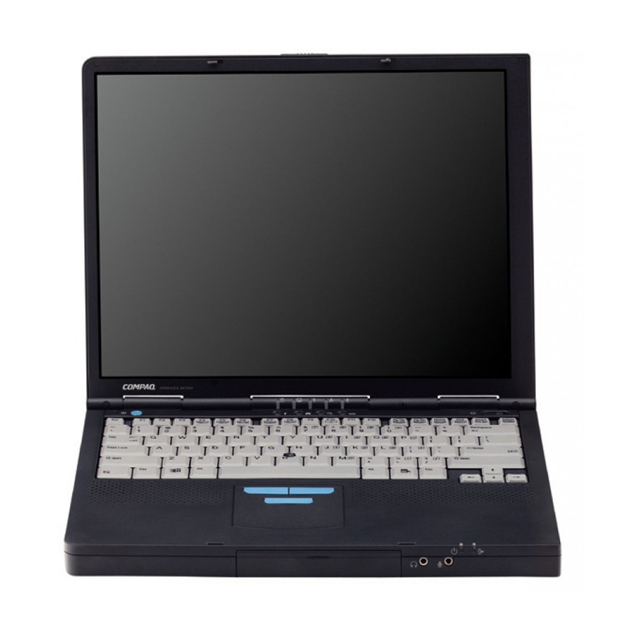
chapter AKING A Pointing Device Components Component Pointing stick Left and right pointing-stick buttons (pointing-stick models only) Scroll pointing-stick button (pointing-stick models only) TouchPad (TouchPad models only Left and right TouchPad buttons (TouchPad models only) OOK AT THE Pointing Device Components Function Moves the pointer. -
Page 12: Top Components
Top Components Component Display switch Suspend button* Hard drive light MultiBay drive light Num lock light Caps lock light Scroll lock light Armada Information Page Easy Access Button MyArmada Easy Access Button*** Search Easy Access Button*** Email Easy Access Button*** 1-2 Taking a Look at the Computer Top Components Function... -
Page 13: Left Side Components
Top Components Component < Power switch Windows application key Displays a shortcut menu for item > Internal speakers Microsoft logo key *In Windows 98 the term sleep button replaces the term suspend button. **In Windows 98 and Windows 2000 Professional the term Standby replaces the term Suspend. -
Page 14: Right Side Components
Right Side Components Component PC Card eject buttons Airflow vent PC Card slots (2) Acoustic vent MultiBay RJ-11 jack (internal modem models only) RJ-45 jack (network models only) 1-4 Taking a Look at the Computer Right Side Components Description Top button: Ejects a PC Card from the top PC Card slot. -
Page 15: Front Components
Front Components Component Hard drive bay Stereo speaker/ headphone jack Microphone jack Power/suspend light Battery light *In Windows 98 and Windows 2000 Professional the term Standby replaces the term Suspend. Front Components Description Holds the primary hard drive. Connects external speakers, headphones, headset, or television audio. -
Page 16: Rear Panel Components
Rear Panel Components Component Infrared port Serial connector External monitor connector Docking connector Connects the computer to a docking base. Parallel connector Power connector USB connector Keyboard/mouse connector 1-6 Taking a Look at the Computer Rear Panel Components Description Links another IrDA-compliant device for wireless communication. -
Page 17: Bottom Components
Bottom Components Component Battery bay Modem slot cover Modem agency approvals label (internal modem models only) MultiBay notch MultiBay release latch Releases a removable drive or battery pack Serial number label Certificate of Authenticity label Bottom Components Description Holds the primary battery. Covers the modem compartment. -
Page 18: Additional Standard Components
Additional Standard Components The components included with the computer vary by geographic region and the computer hardware configuration ordered. The following illustration and table identify the standard components included with most computer models. Some components, such as the hard drive and the primary NOTE: battery pack, ship inside computer bays identified in previous sections and are not included in this illustration. - Page 19 Additional Standard Components Component Weight saver Power cord AC Adapter 3-to-2-prong plug adapter (Japan only) Compaq Portable Product Reference Library CD-ROM QuickRestore package Modem cable (internal modem models only)* Country-specific modem adapter (included with internal modem models by region as required) Network cable (network models only)* Bag containing spare...
-
Page 20: Sing The
chapter SING THE Using the Pointing Device The pointing stick (pointing-stick models) and the TouchPad (TouchPad models) function with any software that supports a Microsoft-compatible mouse. For software that does not support a Microsoft-compatible NOTE: mouse, open Computer Setup, select Advanced!Device Options, then select the Disable Multiple Pointing Devices checkbox. -
Page 21: Identifying Keyboard Components (Touchpad Models)
Identifying Keyboard Components (TouchPad Models) 1 TouchPad 2 Left TouchPad button Navigating with the Pointing Device Task Move the pointer Increase or decrease pointer speed as you move the pointer. To set a pointer speed preference, refer to “Setting Pointing Device Preferences.”... -
Page 22: Setting Pointing-Device Preferences
Pointing-Device Procedures Task Highlight an item.* Select text or an object.* Activate a selection.* Select, then drag and drop an item.* *To perform this task exactly as you would with an external mouse, use the left pointing-device button like an external mouse left button. Setting Pointing-Device Preferences Pointing-stick models—... -
Page 23: Using The Fn Key
Using the Fn Key Many commands are entered by pressing the key simultaneously. For example, Hibernation is initiated by pressings the suspend button, and most of the hotkey Fn + commands in the following section are entered by pressing a function key. If you enable sequential be entered by pressing the simultaneously can also be entered by pressing... -
Page 24: Using Hotkeys
Using Hotkeys Hotkeys are preset combinations of the key that access or execute frequently used system functions. The icons on the function keys To close a window opened with hotkeys, use standard Windows procedures or press the hotkeys again. To use hotkeys on an external keyboard, which does not have an key, press the key only of the hotkey combination. -
Page 25: Switching The Display And Image (Fn+F4)
Switching the Display and Image (Fn+F4) In Windows 95, Windows NT 4.0, or Windows 2000 Professional—Toggle computer display, external display(s), and simultaneous display. The external displays can be connected through the external monitor connector or the composite video-out jack. In Windows 98— When MultiMonitor is enabled, press external display connected to the external monitor connector and disable MultiMonitor. -
Page 26: Setting A Power Conservation Level (Fn+F7)
Setting a Power Conservation Level (Fn+F7) In Windows 98 or Windows 2000 Professional—Press open the Power Schemes window. In Windows 95 or Windows NT 4.0—Press Battery Conservation Settings window. To select a preset battery conservation level, choose among High—Maximizes running time from a single charge. Medium—Balances system performance with running time. -
Page 27: Using The Easy Access Buttons
Using the Easy Access Buttons Each Easy Access Button on the computer keyboard or on an optional external keyboard can be assigned to open an item on the Internet, a network, or a drive with a single keystroke. Internet and Network Connection Requirements for Using Easy Access Buttons Easy Access keys can access an item on the Internet or a network only after your Internet or network services have been set up. -
Page 28: Easy Access Buttons
Easy Access Buttons Button Icon Default Name and Assignment Armada Information Page—Links directly to Compaq Armada user information for quick answers to your computer questions. MyArmada—Opens a personal Internet web page that you can customize with items such as local weather, news, sports, and financial information. -
Page 29: Adding An Easy Access Button Scheme
Adding an Easy Access Button Scheme Button assignments are grouped into schemes, which you create or specify as you change the assignments of individual buttons. Buttons can be renamed or reassigned within any scheme except the default scheme. You can create an unlimited number of schemes. Each button can have the same or different names and assignments in different schemes. -
Page 30: Changing An Easy Access Button Name Or Assignment Within A Scheme
7. Repeat steps 4 to 6 for each Easy Access Button you want to include in the new scheme. 8. Select the Apply or OK button. Changing an Easy Access Button Name or Assignment Within a Scheme To change more than one button name or assignment within NOTE: a scheme, repeat steps 3 to 5 for each button being reassigned. -
Page 31: Displaying Or Selecting An Easy Access Button Scheme
Displaying or Selecting an Easy Access Button Scheme 1. Double-click the Easy Access Buttons icon on the Windows taskbar. Click Start!Settings!Control Panel. Double-click the Keyboard icon, then select the Easy Access Buttons tab. 2. The name of the currently active scheme is displayed in the Scheme box. -
Page 32: Using The Embedded Numeric Keypad
Using the Embedded Numeric Keypad Toggling the Keypad On and Off To convert the embedded numeric keypad section 1 1 1 1 of the keyboard to a keypad—Press numeric keypad is enabled, the characters upper-right on the keypad keys are active and the num lock light 3 is on. To disable the embedded numeric keypad The embedded numeric keypad cannot be enabled while NOTE:... -
Page 33: Enabling The Keypad At Startup
Enabling the Keypad at Startup To set the computer to start up with the embedded numeric keypad enabled— 1. Turn on or restart the computer, then press blinking cursor appears upper-right on the screen. To change the language, press For navigation instructions, press 2. -
Page 34: Inserting , Removing , Or Storing A Battery Pack
chapter NSERTING TORING A Selecting a Battery Pack Location The computer supports up to two battery packs. The battery pack included with the computer can be used only in the battery bay. The battery pack in the battery bay is the primary battery pack. -
Page 35: Replacing A Battery Pack
Storing a Battery Pack CAUTION: high temperatures for extended periods of time. If the computer will be unused and unplugged from an external power source for more than 2 weeks, remove and store the battery pack(s). Proper storage procedures reduce the self-discharge rate of a battery pack. -
Page 36: Removing A Primary Battery Pack From The Battery Bay
Removing a Primary Battery Pack from the Battery Bay 1. If a battery pack is your only power source, initiate Hibernation by pressing If there is drive activity, Hibernation may not occur NOTE: instantly. 2. Close the display. 3. Tilt the computer up 1 and push the battery release latch below the battery bay toward the fan 2 to release the battery pack. -
Page 37: Inserting A Primary Battery Pack Into The Battery Bay
Inserting a Primary Battery Pack into the Battery Bay 1. Close the display. 2. Tilt the computer up 1. 3. With the smooth side of the battery pack facing up and the battery cells facing in, lead the rounded edge of the battery pack into the battery bay. -
Page 38: Removing A Multibay Battery Pack From The Multibay
Removing a MultiBay Battery Pack from the MultiBay 1. If a battery pack is your only power source, initiate Hibernation. 2. With the MultiBay facing you, tilt the computer up 1 and slide the MultiBay release latch toward the opening of the bay 2. -
Page 39: Inserting A Multibay Battery Pack Into The Multibay
Inserting a MultiBay Battery Pack into the MultiBay 1. With the battery pack charge level lights facing up and the battery contacts facing in, insert the battery pack into the MultiBay. 2. If the computer is in Hibernation, slide the power switch to resume normal operation. -
Page 40: Managing Power
chapter ANAGING Selecting a Power Source Task Work within installed applications. Charge or calibrate a battery pack in the computer. Install, reinstall, or modify system software. OWER Power Source Charged battery pack in the computer External power supplied through one of the following devices: AC Adapter Optional docking base... -
Page 41: Using Suspend And Hibernation
Using Suspend and Hibernation Suspend Suspend is an energy-saving feature that conserves power and reduces startup time. Suspend, called Standby in Windows 98, reduces power to system components that are not being used. Suspend can be initiated by you or by the system. When Suspend is initiated, your work is saved in random access memory (RAM) and the screen is cleared. -
Page 42: Suspend, Hibernation, And Shutdown Procedures
Suspend, Hibernation, and Shutdown Procedures All components mentioned in this table are identified in the section immediately following the table. Suspend, Hibernation, and Shutdown Procedures Task Procedure Turn the Slide power switch. computer on from Press suspend shutdown. button.* Shut down Shut down the computer as directed computer. -
Page 43: Identifying Power Controls And The Power/Suspend Light
Identifying Power Controls and the Power/Suspend Light Fn key Suspend button 4-4 Managing Power Power switch Power/suspend light... -
Page 44: Managing Low-Battery Conditions
Managing Low-Battery Conditions Identifying Low-Battery Conditions Low-Battery Condition When a battery pack that is the only source of power available to the computer reaches a low-battery condition The system beeps 5 times. The battery light 1 blinks. Critical Low-Battery Condition If a low-battery condition is not resolved, the computer enters a critical low-battery condition. -
Page 45: Resolving Low-Battery Conditions
Resolving Low-Battery Conditions When External Power Is Available Select one of the following options, depending on your situation: Connect the computer to an electrical outlet with the AC Adapter. Dock the computer in a docking base that is connected to external power. -
Page 46: Charging A Battery Pack
Charging a Battery Pack To charge a battery pack in the computer, supply external power to the computer through the AC Adapter, an optional docking base, or an optional Automobile Power Adapter/Charger. An optional Aircraft Power Adapter does not charge a NOTE: battery pack. -
Page 47: Monitoring The Charge In A Battery Pack
Monitoring the Charge in a Battery Pack Increasing the Accuracy of Battery Charge Displays Follow these guidelines to increase the accuracy of all battery charge displays: Allow a battery pack to discharge to the low-battery level through normal use before charging it. When you charge a battery pack, charge it fully. -
Page 48: Using The Charge Displays On The Screen
Using the Charge Displays on the Screen Interpreting On-Screen Charge Displays Most displays that contain battery charge information identify battery pack locations by number. The battery pack location numbers in a window correspond as follows to the battery pack locations in the computer and an optional docking base. Computer battery bay Computer MultiBay Expansion base right MultiBay or convenience base battery... -
Page 49: Calibrating A Battery Pack
Calibrating a Battery Pack Calibration increases the accuracy of all battery charge displays. Use the calibration utility both to check the calibration of a battery pack and to calibrate a battery pack. A battery pack cannot be calibrated unless the utility reports that it needs calibration. Although the calibration utility supports all battery packs that can be used in the computer, the utility can be run on only one battery pack at a time. -
Page 50: Checking The Calibration Of A Battery Pack
Checking the Calibration of a Battery Pack 1. Insert the battery pack into the computer battery bay or a computer or optional docking base MultiBay. To check the calibration of a battery pack in a docking NOTE: base MultiBay, the computer must be docked and the base must be connected to external power. -
Page 51: Running A Calibration
Running a Calibration 1. Insert the battery pack into the computer battery bay or MultiBay. Then connect the computer to external power through the AC Adapter, and optional docking base that is connected to external power, or an optional Automobile Power Adapter/Charger. -
Page 52: Setting Power Preferences
Setting Power Preferences You can increase, decrease, and allocate the power used by the computer by setting power preferences. Increasing power increases performance, while decreasing power conserves energy and extends battery operating time. By decreasing power to unused components and functions, you can allocate more power to the components and functions you are currently using. -
Page 53: Setting Power Preferences In Windows 95
Setting Power Preferences in Windows 95 Preference Select a preset battery conservation level that applies whenever the computer is running on battery power. Create a Custom battery conservation level that includes the following settings and applies whenever the computer is running on battery power: Brightness Processor speed Suspend... - Page 54 Setting Power Preferences in Windows 95 Preference Change location of Hibernation file. Enable/Disable Hibernation. Turn off power to an optional PC Card modem when it is not being used. Continued Procedure from Control Panel Select Power!Hibernation tab, then select the new location from the Drive for Hibernation File drop-down list box.
-
Page 55: Setting Power Preferences In Windows 98
Setting Power Preferences in Windows 98 Preference Select a preset battery conservation level that applies whenever the computer is running on battery power. Create a Custom battery conservation level for screen brightness that applies whenever the computer is running on battery power. Set Hibernation timeout. -
Page 56: Setting Power Preferences In Windows Nt 4.0
Setting Power Preferences in Windows NT 4.0 Preference Select a preset battery conservation level that applies whenever the computer is running on battery power. Create a Custom battery conservation level that includes the following settings and applies whenever the computer is running on battery power: Suspend Hard disk idle... - Page 57 Setting Power Preferences in Windows NT 4.0 Preference Enable/disable low-battery warning beeps. Exit Suspend after a user- selected timeout. Set Hibernation timeout. Change location of the hibernation file. Enable/Disable Hibernation. Select Compaq Power!Hibernation tab, 4-18 Managing Power Continued Procedure from Control Panel Select Compaq Power!Battery Conservation Settings tab, then select the On or Off radio button.
-
Page 58: Setting Power Preferences In Windows 2000 Professional
Setting Power Preferences in Windows 2000 Professional Preference Select a preset battery conservation level that applies whenever the computer is running on battery power. Create a Custom battery conservation level that includes the following settings and applies whenever the computer is running on battery power: Brightness Processor speed... -
Page 59: Using Speedstep Performance Modes
Using SpeedStep Performance Modes The Intel Pentium III with SpeedStep technology can enable an automatic change in processor speed when the power source changes between AC power and battery power. Choosing a Performance Mode The SpeedStep technology offers two preset performance modes: In Maximum Performance mode, the processor runs at full speed to provide maximum performance. -
Page 60: Setting Speedstep Preferences
Setting SpeedStep Preferences If the SpeedStep window and icon are not accessible, they NOTE: may be disabled in Computer Setup. To enable the window and icon (and other settings in the SpeedStep window), refer to the table in “Using Computer Setup,” later in this section. Using the SpeedStep Window To open the SpeedStep window from the desktop—... - Page 61 Setting SpeedStep Preferences in the SpeedStep Window Preference Turn off the audible alert of a performance mode change. Set the computer to change automatically between Maximum Performance mode while running on AC power and Battery Optimized mode while running on battery power Disable all settings in the main SpeedStep window.
- Page 62 Using the SpeedStep Icon The SpeedStep icon displays on the taskbar by default and changes to indicate whether the computer is running in Maximum Performance or Battery Optimized mode. The icon can also be used for the tasks described in the following table. Task Display current performance mode.
-
Page 63: Battery Conservation Checklists
Battery Conservation Checklists Battery Conservation Practices Exit modem applications and turn off local area network (LAN) connections when you are not using them. Disconnect external equipment you are not using that is not connected to an external power source. If you leave your work, initiate Suspend (Standby) or Hibernation or shut down the computer. -
Page 64: Using Drives
chapter SING RIVES Caring for Drives CAUTION: a drive: If you are inserting or removing a hard drive, shut down the computer. Do not remove a hard drive while the computer is on or in Suspend (Standby) or Hibernation. To ensure that the computer is not in Hibernation, turn the computer on, then shut it down. -
Page 65: Selecting Drive Locations
Selecting Drive Locations The computer has three bays for drives. The hard drive bay supports only a hard drive. The hard drive in the hard drive bay is the primary hard drive. The MultiBay supports any 12.7 mm drive, such as a diskette drive, SuperDisk LS-120 drive, CD-ROM drive, DVD-ROM drive, or a second hard drive. -
Page 66: Hard Drives
Hard Drives WARNING: allow the internal system components to cool before touching them. Removing a Hard Drive from the Hard Drive Bay 1. Save your work, then shut down the computer. 2. Push down the hard drive tab on the front of the hard drive until it snaps away from the front of the computer 1. -
Page 67: Inserting A Hard Drive Into The Hard Drive Bay
Inserting a Hard Drive into the Hard Drive Bay 1. Save your work, then shut down the computer. 2. Slide the hard drive into the hard drive bay until it is seated and the cover is flush with the front of the computer. 5-4 Using Drives... -
Page 68: Inserting A Hard Drive Into A Multibay Hard Drive Adapter
Inserting a Hard Drive into a MultiBay Hard Drive Adapter 1. Push the two slide tabs 1 toward the outside of the adapter. 2. Lower the drive, label side up, into the adapter 2, then slide the drive connectors on the drive toward the drive connectors in the adapter 3 until the connectors engage and the drive is seated. -
Page 69: Inserting A Hard Drive Assembly Into The Multibay
Inserting a Hard Drive Assembly into the MultiBay 1. Save your work, then shut down the computer. 2. Be sure the slide tabs on the sides of the Armada MultiBay hard drive adapter are closed flush with the sides of the adapter. -
Page 70: Removing A Hard Drive Assembly From The Multibay
Removing a Hard Drive Assembly from the MultiBay 1. Save your work, then shut down the computer. 2. Close the display. 3. With the MultiBay facing you, tilt the computer up 1. 4. Slide the MultiBay release latch toward the opening of the MultiBay 2. -
Page 71: Cd-Rom And Dvd-Rom Drives
CD-ROM and DVD-ROM Drives CD-ROM drives and DVD-ROM drives can be inserted and removed from the computer MultiBay without shutting down the computer. Removing a CD-ROM Drive or DVD-ROM Drive 1. Remove the compact disc from the media tray. 2. Close the tray. 3. -
Page 72: Inserting A Cd-Rom Drive Or Dvd-Rom Drive
Inserting a CD-ROM Drive or DVD-ROM Drive With the drive connector facing in, slide the drive into the MultiBay until the connectors engage and the drive is seated. Using Drives 5-9... -
Page 73: Inserting A Disc Into A Cd-Rom Drive Or Dvd-Rom Drive
Inserting a Disc into a CD-ROM Drive or DVD-ROM Drive 1. Turn on the computer. 2. Press the media eject button on the front panel 1 to release the media tray. 3. Slowly pull out the tray until it is fully extended. 4. -
Page 74: Removing A Disc From A Cd-Rom Drive Or Dvd-Rom Drive
Removing a Disc from a CD-ROM Drive or DVD-ROM Drive 1. Turn on the computer. 2. Press the eject button on the front panel 1 to open the media tray. 3. Slowly pull out the tray until it is fully extended. 4. -
Page 75: Diskette Drive And Superdisk Ls-120 Drive
Diskette Drive and SuperDisk LS-120 Drive Diskette drives and SuperDisk LS-120 drives can be inserted and removed from the computer MultiBay without shutting down the computer. Removing a Diskette Drive or SuperDisk LS-120 Drive from the MultiBay 1. Remove the diskette from the drive. 2. -
Page 76: Inserting A Diskette Drive Or
Inserting a Diskette Drive or SuperDisk LS-120 Drive into the MultiBay With the drive connector facing in, slide the drive into the MultiBay until the connectors engage and the drive is seated. Using Drives 5-13... -
Page 77: Using A Diskette Drive Externally
Using a Diskette Drive Externally By using a diskette drive externally, the drive can be accessed while another drive or a battery pack is in the MultiBay. An external diskette drive assembly (a diskette drive inside an external diskette drive bay) is included with the computer. The external diskette drive bay supports only a diskette drive. - Page 78 Removing a Diskette Drive from the External Diskette Drive Bay A diskette drive must be removed from the external diskette drive bay before it can be inserted in the MultiBay. To remove the diskette drive from the drive bay— 1. Turn the diskette drive bay upside down. 2.
-
Page 79: Inserting A Diskette Into A Diskette Drive Or Superdisk Ls-120 Drive
Inserting a Diskette into a Diskette Drive or SuperDisk LS-120 Drive 1. Hold the diskette by the edge covered by the label, label facing up. 2. Gently push the diskette into the drive until it clicks into place. The media eject button ejects to show that the diskette is inserted correctly. -
Page 80: Changing The Startup Sequence With Multiboot
Changing the Startup Sequence with MultiBoot When more than one drive is in the system, the computer selects the drive to start from by searching sequenced locations for, first, a bootable CD-ROM or DVD-ROM; second, a bootable diskette; and third, a bootable hard drive. A bootable device or medium contains files needed by the NOTE: computer to start up and operate properly. -
Page 81: Selecting A Multiboot Utility
Changing the boot order also changes the logical drive IMPORTANT: designations. For example, if you start up from a hard drive in the computer MultiBay, that hard drive becomes drive C and a hard drive in the hard drive bay becomes drive D. If you start up from a diskette drive in the external diskette drive bay, that diskette drive becomes drive A. -
Page 82: Changing The Startup Sequence In Compaq Computer Security
Changing the Startup Sequence in Compaq Computer Security 1. Access the Compaq Computer Security window: Select Start!Settings!Control Panel. Select the Compaq Computer Security icon. Right-click the Compaq Computer Security icon in the Windows taskbar, then select Security Properties. 2. Select the Boot Security tab. 3. -
Page 83: Securing The Computer
chapter ECURING THE Security Features Quick Reference To Protect Against This Risk If You Forget a Password If you forget your power-on or setup (administrator) password, refer to “Worldwide Telephone Numbers” in Appendix A to contact a Compaq authorized service provider. If you forget both your user and master DriveLock passwords, the hard drive is permanently unusable. -
Page 84: Using Security Utilities
Using Security Utilities All security features except DriveLock can be set in either the Computer Setup utility or the Compaq Computer Security utility, unless otherwise noted. The Computer Setup utility can be used even when your Windows operating system is not functioning or will not load. -
Page 85: Using A Power-On Password
Using a Power-on Password A power-on password Prevents unauthorized use of the computer. Once set, it must be entered each time the computer is turned on or restored from Hibernation. Enables you to use Quick Controls. Is not case sensitive, can be the same as any other 7-character password, and can include up to 7 alphanumeric characters. - Page 86 Setting a Power-on Password in Compaq Computer Security 1. Access the Computer Security tab. In Windows 95 or Windows 98— Select Start!Settings!Control Panel. Select the Passwords icon, then select the Computer Security tab. Right-click the Compaq Computer Security icon in the Windows taskbar, then select Password Properties.
-
Page 87: Entering A Power-On Password
Changing or Deleting a Power-on Password at the Power-on Password Prompt 1. Turn on (do not restart) the computer. 2. At the password prompt To change a power-on password—Type the old password followed by a forward slash (“/”), the new password followed by a forward slash, then the new password followed by a forward slash. -
Page 88: Using Quick Controls
Using Quick Controls When a power-on password is set, the following Quick Controls are available: QuickLock—Disables the keyboard and pointing device. (In Compaq Computer Security this option is called Enable QuickLock of the Keyboard.) QuickLock on Suspend—Sets the computer to initiate QuickLock whenever the computer enters Suspend (Standby). - Page 89 Setting Quick Controls in Computer Setup 1. Turn on or restart the computer, then press blinking cursor appears upper-right on the screen. To change the language, press For navigation instructions, press 2. Select Security!Password Options. Enter your preferences, then press F10.
-
Page 90: Initiating Quicklock
2. Press the Power-on Password Options button. The Options button is not available unless a power-on NOTE: password is set or if a USB keyboard has ever been connected to the computer. 3. Select the checkbox for each Quick Control you want to enable. -
Page 91: Using A Setup (Administrator) Password
Using a Setup (Administrator) Password This password Is called a setup password in Computer Setup and an administrator password in Compaq Computer Security. Protects the configuration settings and system identification information in both the Computer Setup and Compaq Computer Security utilities. Once set, this password must be entered to Access Computer Setup. -
Page 92: Entering A Setup (Administrator) Password
To delete a setup (administrator password)—Type the current password in the Old Password field, then press 3. To save your preferences, then close Computer Setup and restart the computer, select File!Save Changes and Exit, then press Enter. 4. When prompted to confirm your action, press Setting a Setup (Administrator) Password in Compaq Computer Security 1. -
Page 93: Using Drivelock
Using DriveLock CAUTION: the DriveLock master password, the protected hard drive is permanently unusable. To access the DriveLock settings in Computer Setup, IMPORTANT: you must open Computer Setup after shutting down, then turning on the computer. If you open Computer Setup from a Windows restart, DriveLock settings are not accessible. -
Page 94: Protecting A Hard Drive With Drivelock
A user or master password can be up to 32 alphanumeric characters and is not case sensitive. The user and master password can be the same. A user or master password that is 7 characters or less can be the same as any other password. -
Page 95: Accessing A Protected Hard Drive
9. To confirm DriveLock protection on the drive you have selected, type DriveLock in the confirmation field, then press F10. 10. To save your DriveLock settings, then close Computer Setup and restart the computer, select File!Save Changes and Exit, then press Enter. -
Page 96: Disabling A Device
4. Select the location of the hard drive, then press To change a user or master password—In the field of the password you want to change, type the current password in the Old Password field, type the new password in the New Password and Verify New Password fields, then press To remove DriveLock protection from the drive—... -
Page 97: Enabling Or Disabling A Device In Compaq Computer Security
Enabling or Disabling a Device in Compaq Computer Security 1. Access the Compaq Computer Security window: Select Start!Settings!Control Panel. Select the Compaq Computer Security icon. Right-click the Compaq Computer Security icon in the Windows taskbar, then select Security Properties. 2. Select a tab: To enable or disable the serial, infrared, parallel, or USB port—Select the Port Security tab. -
Page 98: Managing System Information
Managing System Information You can use either Computer Setup or Compaq Computer Security to Display or enter the computer serial number, asset tag, and ownership tag. Display or enter a battery pack serial number and asset tag. Display or enter a docking station serial number and asset tag. -
Page 99: Entering And Displaying System Information In Compaq Computer Security
To enable/disable the reporting of the processor serial number by the processor to software—Select Advanced menu!Device Options. To specify how the computer recognizes multiple, identical docking bases that are identically equipped— Select Advanced menu!Device Options. (Select Disable to recognize the docking abases as a single docking base; select Enable to recognize the docking bases individually, by serial number.) 3. - Page 100 To view or enter information about an optional docking base—Select the docking base in the Manageable Devices list. View or enter information in the following text boxes. The Serial Number box is Read Only. The Asset Tag box can be used to describe the docking base using no more than 16 alphanumeric characters.
- Page 101 Displaying or Securing the Processor Serial Number in Compaq Computer Security 1. Access the Compaq Computer Security window: Select Start!Settings!Control Panel. Select the Compaq Computer Security icon. Right-click the Compaq Computer Security icon in the Windows taskbar, then select Security Properties. 2.
-
Page 102: Connecting An Optional Cable Lock
Connecting an Optional Cable Lock Loop the cable around a secure object, then insert the cable lock 1 into the security cable slot 2 and lock it with the cable lock key 3. 6-20 Securing the Computer... -
Page 103: Using An Internal Modem
chapter SING AN The information in this chapter applies to all computer models with internal modems. The modem does not support the modem pass-through NOTE: connection available on some optional docking bases. Connecting the Modem Cable The internal modem uses a universal DAA (Direct IMPORTANT: Access Arrangement) that supports multiple countries. - Page 104 To connect the modem to an RJ-11 wall jack— The modem cable, which has a 6-pin RJ-11 connector IMPORTANT: at each end, may contain noise suppression circuitry 1. This circuitry prevents interference with TV and radio reception. Orient a cable with this circuitry as shown in the following illustration.
-
Page 105: Setting Up The Modem
Setting Up the Modem The following procedures are necessary only if your modem name does not display at Start!Settings!Control Panel! Modem. In Windows 95 or Windows 98—Select Start!Settings! Control Panel!Modem. The Install New Modem setup wizard displays. To set up the modem with this wizard: 1. -
Page 106: Selecting Communication Software
Selecting Communication Software You can operate the modem with preinstalled or optional software. To use preinstalled modem software—Select Start!Programs. Then, For terminal emulation and data transfer In Windows 95, Windows NT 4.0, or Windows 98, select Accessories!HyperTerminal. In Windows 2000 Professional select Accessories! Communications!Hyperterminal. - Page 107 To load a script file for Lotus Notes version 4.x or later— 1. In Windows Explorer select C:\Program Files\Compaq\ CPQLANModem\Modem\Scripts. 2. Copy the LN56kcom.mdm file in the Scripts folder to the Notes\Data\Modems folder. 3. Open the Lotus Notes application. 4. From the menu bar, select File!Tools!User Preferences!Ports icon.
-
Page 108: Using Modem Commands And Dial Modifiers
Using Modem Commands and Dial Modifiers You can configure most communications software without the use of AT commands or dial modifiers. If you prefer to configure the modem using AT commands, In Windows 95, Windows NT 4.0, or Windows 98, select Accessories!HyperTerminal. -
Page 109: Using The Modem While Traveling Internationally
Using the Modem While Traveling Internationally Using a Country-Specific Modem Adapter Telephone jacks vary by country. The modem cable included with the computer plugs directly into an RJ-11 telephone jack. To plug the modem cable into a different type of telephone jack, you must use a country-specific modem cable adapter. -
Page 110: Selecting A Country-Specific Modem Configuration
Selecting a Country-Specific Modem Configuration The internal modem is configured to meet operating approval in the country where you purchased your computer. To set the modem to comply with telecommunications standards and regulations in other countries, you must change the country selection setting. -
Page 111: Travel Connection Checklist
In Windows 2000 Professional—Select Start!Settings! Control Panel!Phone and Modems Options. Select the Dialing Properties tab, then 1. On the Locations list, select the location from which you are dialing. 2. Select the Edit button. 3. Select the new country from the drop-down list in the Country/region box. - Page 112 In Windows 2000 Professional— 1. Select Start!Settings!Control Panel!Phone and Modem Options!Modem tab. 2. Select your modem, then select Properties. 3. Select the General tab, then clear the Wait for Dial Tone Before Dialing checkbox. If you continue to receive the No Dial Tone error NOTE: message after clearing the checkbox, select Start!Settings! Control Panel!Phone and Modems Options.
-
Page 113: Reinstalling Or Updating Drivers (Windows 95 Or Windows 98)
Reinstalling or Updating Drivers (Windows 95 or Windows 98) To update or reinstall modem drivers: First, uninstall the currently loaded modem drivers. Second, install or restore the modem drivers. Uninstalling Modem Drivers (Windows 95 or Windows 98) 1. Select Start!Settings!Control Panel, then double-click Add/Remove Programs and select the Install/Uninstall tab. -
Page 114: Reinstalling Or Updating Drivers (Windows Nt 4.0)
Reinstalling or Updating Drivers (Windows NT 4.0) To uninstall or reinstall modem or LAN drivers in IMPORTANT: Windows NT 4.0, you must log in to Windows NT with Administrator privileges. To update or reinstall modem drivers: First, uninstall the currently loaded modem drivers. Second, install or restore the modem drivers. -
Page 115: Reinstalling Or Updating Drivers (Windows 2000 Professional)
Reinstalling or Updating Drivers (Windows 2000 Professional) To uninstall or reinstall modem or LAN drivers in IMPORTANT: Windows 2000 Professional, you must log in to Windows 2000 Professional with Administrator privileges. To update or reinstall modem drivers: First, uninstall the currently loaded modem drivers. Second, install or restore the modem drivers. - Page 116 chapter ONNECTING TO A ETWORK A network computer model can be connected to a Local Area Network (LAN). A network computer model Has an internal modem/NIC (network interface card) combination card. Has an RJ-45 jack on the right side. Has preinstalled LAN drivers. Supports network speeds up to 10 Mbps when connected to a 10BaseTX network.
-
Page 117: Connecting To A Lan
Connecting to a LAN The network cable, which has an 8-pin RJ-45 IMPORTANT: connector at each end, may contain noise suppression circuitry 1. This circuitry prevents interference with TV and radio reception. Orient a cable with this circuitry as shown in the following illustration. -
Page 118: Accessing The Network At Startup
Accessing the Network at Startup A network computer model supports both the PXE (Preboot eXecution Environment) and RPL (Remote Program Load) preboot network protocols. To connect to your PXE or RPL server during startup—Press when the Network Service Boot message appears very briefly in the lower-right corner of the screen. - Page 119 To uninstall LAN drivers— 1. On the Install/Uninstall tab, select Intel PRO Ethernet Adapter and Software from the list of programs. 2. Select the Add/Remove button. 3. Select OK to confirm the removal. 4. Restart the computer, then begin installing the modem drivers. Reinstalling LAN and Modem Drivers (Windows 95 and Windows 98) To reinstall LAN drivers—...
- Page 120 3. Select the Next button, then continue to select the Next button on succeeding screens until the computer copies the modem drivers. 4. To complete the installation of the modem drivers, select Finish. It is not necessary to restart the computer after NOTE: installing the modem drivers.
- Page 121 Uninstalling Modem and LAN Drivers (Windows NT 4.0) To uninstall modem drivers— 1. Select Start!Settings!Control Panel, then double-click Add/Remove Programs. 2. Select Compaq 56K (V.90) Mini PCI from the list of programs. 3. Select the Add/Remove button. 4. Select Yes to confirm the removal. 5.
- Page 122 To install Windows NT Networking— 1. Select Start!Settings!Control Panel, then double-click the Network icon. 2. At the Windows NT Networking installation prompt, select the Yes button. 3. Select Wired to the Network, then select the Next button. 4. Select the Select from List button. 5.
- Page 123 Reinstalling LAN Drivers (Windows NT 4.0) 1. Select Start!Settings!Control Panel, then double-click the Network icon. 2. Select the Adapters tab. 3. Select the Add button. 4. Select the Have Disk button. 5. When prompted for the path to the Intel PRO/100+ Mini PCI drivers, type the following, then select the OK button.
- Page 124 Reinstalling or Updating Drivers (Windows 2000 Professional) To uninstall or reinstall modem or LAN drivers in IMPORTANT: Windows 2000 Professional, you must log in to Windows 2000 Professional with Administrator privileges. To update or reinstall modem and LAN drivers: First, uninstall the currently loaded modem drivers. Second, install or restore the LAN drivers.
- Page 125 Installing or Restoring LAN Drivers (Windows 2000 Professional) 1. Select Start!Settings!Control Panel, then double-click the System icon. 2. Select the Hardware tab, then double-click the Device Manager button. 3. Double-click Network adapters, then double-click Intel PRO/100+ MiniPCI. 4. Select the Driver tab, then the Update Driver button. 5.
-
Page 126: Managing Random Access Memory (Ram)
chapter PGRADING Managing Random Access Memory (RAM) To view the amount of RAM in the system, select Start! Settings!Control Panel!Compaq Diagnostics. You can increase RAM with optional memory expansion boards or PC Cards. For ordering information, go to the Compaq website at http://www.compaq.com, or refer to Appendix A to contact a Compaq authorized dealer, reseller, or service provider. -
Page 127: Inserting Or Removing A Memory Expansion Board
Inserting or Removing a Memory Expansion Board WARNING: internal compartment on the computer. All other areas that require a tool to access should be opened only by a Compaq authorized service provider. WARNING: pack before installing a memory expansion board can damage the equipment and expose you to the risk of electrical shock. -
Page 128: Removing A Memory Expansion Board
5. Release the four tabs located along the top of the keyboard to release the keyboard from the computer 1. 6. Carefully fold the computer keyboard away from the computer 2. Removing a Memory Expansion Board 1. Pull away the retention clips on each side of the memory expansion board 1. -
Page 129: Inserting A Memory Expansion Board
Inserting a Memory Expansion Board All memory expansion boards supported by the computer Can be used in either of the two memory expansion slots. Are keyed (notched) to ensure correct positioning. 1. Slide the memory expansion board into an empty memory expansion slot at a 45-degree angle 1 until it is seated. -
Page 130: Using The Internal Microphone And The Internal Speakers
chapter SING UDIO AND EATURES Using the Internal Microphone and the Internal Speakers The microphone 1 has a standard sensitivity of -50 dB and supports audio input optimally when the display is open. The two internal speakers 2 provide stereo audio playback for multimedia applications. -
Page 131: Connecting An External Audio Device
Connecting an External Audio Device CAUTION: plug a single-sound channel (monaural) connector into the stereo speaker/headphone jack. Selecting an Audio Connector To Connect This Device Stereo speakers, headphones, headset, or audio/visual device such as a television or VCR Single sound channel microphone Connecting a Device to the Microphone Jack The microphone jack supports a single sound channel (monaural) -
Page 132: Connecting A Device To The Stereo Speaker/Headphone Jack
Connecting a Device to the Stereo Speaker/Headphone Jack WARNING: before putting on headphones or a headset. Use only a 3.5-mm stereo plug. For best sound quality, Headphones should be 32 ohms. External speakers should be at least 8 ohms. Connecting an external audio device to the stereo speaker/ headphone jack disables the computer stereo speakers. -
Page 133: Connecting An External Video Device
Connecting an External Video Device The composite video-out jack can support— Any device, such as a television, VCR, camcorder, overhead projector, or video capture card, that accepts video-in through a standard composite video connector. Video signals only. If you are setting up a configuration that combines audio and video functions, such as playing a DVD movie to a television, connect the device audio to the stereo/speaker headphone jack. -
Page 134: Changing The Video Mode
Changing the Video Mode Color television standard modes vary even within regions. NOTE: However, NTSC is common in North America; PAL, in Europe, Africa, and the Middle East; NTSC-J, in Japan; and PAL-M, in Brazil. Other South and Central American regions may use NTSC, PAL, or PAL-M. -
Page 135: Installing Cardware (Windows Nt 4.0)
chapter PC C SING A PC Card is a credit card–sized accessory designed to conform to the standard specifications of the Personal Computer Memory Card International Association (PCMCIA). The computer supports both 32-bit (CardBus) and 16-bit PC Cards. Installing CardWare (Windows NT 4.0) Unicore Software CardWare provided by Compaq is available on your hard drive but is not installed. -
Page 136: Selecting A Pc Card Slot
Selecting a PC Card Slot PC Cards are classified as Type I, Type II, and Type III. The three types are about the same length and width, but vary in thickness. Type III cards are the thickest, at less than one-half inch (10.5 mm). -
Page 137: Inserting A Pc Card
Inserting a PC Card CAUTION: pressure as you insert a PC Card into a PC Card slot Unless the computer is running Windows NT 4.0 without NOTE: CardWare provided by Compaq, it is not necessary to shut down the computer before inserting a PC Card unless you are specifically instructed to do so in the PC Card documentation. -
Page 138: Removing A Pc Card
Removing a PC Card First, prepare the system for the PC Card removal: CAUTION: Windows 98, or Windows 2000 Professional, failure to stop a PC Card before removing it may result in loss of work or a system lockup. In Windows 95, Windows 98, or Windows 2000 Professional—If the computer is on, stop the PC Card before you remove it. -
Page 139: Communicating With Infrared
chapter SING NFRARED Communicating with Infrared If the computer is running Windows 98, Windows 2000 Professional, or a preinstalled Windows 95 operating system, the computer is IrDA-compliant (4Mbps standard) and can communicate with another infrared-equipped device that is also IrDA-compliant. Infrared communication Occurs through the infrared port illustrated below. -
Page 140: Configuring The Infrared Port
Configuring the Infrared Port If you are using optional infrared software, the following information may be helpful. In Windows 95 or Windows 98— The infrared port default settings are: Port, COM3; address, 3; Interrupt Request (IRQ), 3. If you use Direct Cable Connection and the utility prompts you to choose a port for the infrared connection, you can select Serial Cable on COM4 or, if the computer is running a preinstalled Windows 95 or Windows 98 operating system,... -
Page 141: Positioning The Infrared Port
To enable or disable Infrared Monitor search: 1. Open the Infrared Monitor dialog box by selecting the Infrared icon in the taskbar!Options tab. To enable Infrared Monitor search, select the checkbox for Search For and Provide Status for Devices in Range. To disable Infrared Monitor search, clear the checkbox. -
Page 142: Setting Up Insight Management Agents
chapter SING NTELLIGENT ANAGEABILITY Intelligent Manageability comprises software tools that can help you and/or your Information Services department track, troubleshoot, protect, and maintain the system. Intelligent Manageability uses such tools as Insight Management Agents, Compaq Diagnostics, Computer Setup, and Compaq Computer Security to facilitate the following: Asset Management—Provides detailed configuration and diagnostic information. -
Page 143: Using Fault Management Alerts
Using Fault Management Alerts Identifying a Fault Management Alert The computer is preset to monitor certain hardware components. If problems are found, the following alerts may display. Hard drive alert—Warns up to 72 hours in advance of impending hard drive problems; can be set to initiate a software backup. -
Page 144: Selecting Computer Setup Or Compaq Diagnostics
chapter OMPUTER IAGNOSTICS Selecting Computer Setup or Compaq Diagnostics The computer features two Compaq system management utilities: Computer Setup is a system information and customization utility that can be used even when your operating system is not working or will not load. This utility includes settings that are not available in Windows. -
Page 145: Using Computer Setup
Using Computer Setup Information and settings in Computer Setup are accessed from the File, Security, or Advanced menus: 1. Turn on or restart the computer. When the blinking cursor appears upper-right on the screen, press To change the language, press To view navigation information, press To return to the Computer Setup menu, press 2. -
Page 146: Selecting From The Security Menu
Selecting from the Security Menu For more information about the security features available NOTE: on the Security menu, refer to Chapter 6 in this guide. Selecting from the Security Menu Select Setup password Power-on password DriveLock passwords Password options NOTE: Password options can be selected only when a power-on password is set. -
Page 147: Selecting From The Advanced Menu
Selecting from the Advanced Menu Selecting from the Advanced Menu Select Language (or press Boot Options Device Options 14-4 Computer Setup and Diagnostics Utilities To Do This Change the Computer Setup language. Enable/disable QuickBoot, which starts the computer more quickly by eliminating some startup tests. - Page 148 Selecting from the Advanced Menu Select Device Options (continued) *Video modes vary even within regions. However, NTSC is common in North America; PAL, in Europe, Africa, and the Middle East; NTSC-J, in Japan; and PAL-M, in Brazil. Other South and Central American regions may use NTSC, PAL, or PAL-M.
-
Page 149: Using Compaq Diagnostics
Using Compaq Diagnostics When you access Compaq Diagnostics, a scan of all system components appears on the screen before the Compaq Diagnostics window opens. You can display more or less information from anywhere within Compaq Diagnostics by selecting Level on the menu bar. Compaq Diagnostics is designed to test Compaq components. - Page 150 4. Select a test type: Quick Test runs a quick, general test on each device in a selected category. Complete Test performs maximum testing on each device in a selected category. Custom Test performs maximum testing on a selected device. To run all tests for your selected device, select the Check All button.
-
Page 151: Updating Your System
chapter AINTENANCE HIPPING Updating Your System Compaq recommends that you install all software IMPORTANT: updates as they become available. However, if your system is connected to a network, you may need to confer with your Information Services department before updating system ROM. Obtaining Update Information and Software Checking the Compaq Website You can obtain the latest available update information and... -
Page 152: Downloading Software Updates
Subscribing to the Compaq Support Software CD You can subscribe to the Compaq Support Software CD that contains detailed software support information and the software and installation instructions for the latest device drivers, system ROMs, and utilities. To obtain ordering information—Contact your Compaq authorized dealer, reseller, or service provider or go to the Compaq website at http://www.compaq.com. -
Page 153: Installing Software Updates
Installing Software Updates Installing a Downloaded SoftPaq 1. Open and read the Readme.txt file included with the download. 2. Follow the installation instructions in the Readme.txt file or on the Compaq website. Installing a System ROM The easiest way to install a system ROM is from a diskette. A system ROM cannot be installed directly from any other NOTE: drive medium, including a SuperDisk LS-120 disk. -
Page 154: Restoring Software
Restoring Software If it ever becomes necessary, you can restore any or all of the software for the operating system and language you selected during initial setup. The software and instructions for restoring it are in the QuickRestore package included with the computer. If you are restoring a Windows NT 4.0 operating system, NOTE: refer to “Installing CardWare (Windows NT 4.0)”... -
Page 155: Monitoring Computer Temperature
Monitoring Computer Temperature When the computer is run at high power levels or for an extended period of time, it is normal for the computer to feel warm to hot. The computer complies with international safety standards for temperatures of user-accessible surfaces. For more information about operating temperatures, refer to Appendix D in this guide. -
Page 156: Caring For The Computer
Caring for the Computer WARNING: internal components, do not allow liquids to drip into the computer keyboard. CAUTION: anything on top of the computer when it is closed. CAUTION: and discolor the plastic. Keep the computer away from excessive moisture and temperature extremes. -
Page 157: Traveling With The Computer Checklist
Traveling with the Computer Checklist Take along a backup of your work. Do not pack the backup with the computer. Hand carry the computer. Do not check it with your luggage. Do not expose the computer or diskettes to a magnetic security detector. - Page 158 chapter ROUBLESHOOTING Problems that occur while using the computer may originate with the computer, the operating system, a software application, or an optional docking base or external device: For problems that may not originate with the computer, refer to your operating system, docking base, software application, or external device documentation.
-
Page 159: Quick Solutions Checklist
Quick Solutions Checklist To reset a locked system, press and hold the suspend button NOTE: while sliding the power switch. Is adequate power available to the computer? If the computer is connected to an electrical outlet Are all power connections, including the power cord and any adapters required by your configuration, secure? Is the electrical outlet providing a standard... -
Page 160: Solving Audio Problems
Solving Audio Problems Problem Possible Cause Internal speaker Volume may be turned does not produce off or set too low. sound when an external audio source is connected to the stereo line-in jack. Line input may not be connected properly. Headphones or speakers are connected to the stereo speaker/... -
Page 161: Control Panel
Solving Audio Problems Problem No sound from headphones. Volume too low or too loud. 16-4 Troubleshooting Continued Possible Cause Volume or mixing controls set incorrectly. Sound source not selected. The headphones are connected to the wrong jack. Volume or mixing controls set incorrectly. -
Page 162: Solving Battery Problems
Solving Battery Problems Problem Possible Cause Computer is Battery pack charge is beeping and low. battery light is blinking. Computer Volume turned down battery light too low. blinks to indicate low battery condition, but computer does not beep. Battery pack will Battery pack was not charge. - Page 163 Solving Battery Problems Problem Battery charge does not last very long. Date and time must be set every time computer is turned on. Battery gauge seems inaccurate. Battery pack is warm after charging. 16-6 Troubleshooting Continued Possible Cause Battery is exposed to higher temperatures.
-
Page 164: Solving Cd-Rom Drive/Dvd-Rom Drive Problems
Solving CD-ROM drive/DVD-ROM Drive Problems Problem Possible Cause Drive cannot Disc is not properly read a disc. seated in the drive. Disc is loaded in the loading tray upside down. Disc has a scratch on its surface. CD-ROM drive Drive is not connected or DVD-ROM properly. -
Page 165: Solving Diskette Drive/Superdisk Ls-120 Drive Problems
Solving Diskette Drive/SuperDisk LS-120 Drive Problems Problem Drive cannot write to a diskette. System cannot start up from diskette drive or SuperDisk LS-120 drive. 16-8 Troubleshooting Possible Cause Diskette is not formatted. Diskette is write- protected. Writing to the wrong drive. -
Page 166: Solving Hard Drive Problems
Solving Hard Drive Problems Problem Possible Cause Accessing Hard drive entered low information on power state due to the hard drive timeout and is now is much slower exiting from it. than usual. Hard drive is fragmented/not optimized or has errors Hard drive does Hard drive is not seated not work. -
Page 167: Solving Infrared Problems
Problem Cannot communicate with another computer. 16-10 Troubleshooting Solving Infrared Problems Possible Cause The appropriate software is not running on both computers. The other computer does not have an IrDA- compliant infrared port. Your Compaq computer uses the IrDA communications protocol. The pathway between the infrared ports is obstructed, one port is... - Page 168 Solving Infrared Problems Problem Possible Cause Cannot transmit Direct sunlight, data. fluorescent light, or flashing incandescent light is close to the infrared connections. There is interference from other wireless devices. There is a physical obstruction in the way. One of the units was moved during data transmission.
-
Page 169: Solving Keyboard/Numeric Keypad Problems
Solving Keyboard/Numeric Keypad Problems Problem Screen is blank and keyboard is working. Embedded numeric keypad keyboard is disabled. Problem Modem loses connection. 16-12 Troubleshooting Possible Cause A screen timeout has been initiated. QuickLock/QuickBlank has been initiated. LCD has been disabled. Num Lock function is not turned on. - Page 170 Solving Modem Problems Problem Possible Cause Modem not Modem is not set up responding. correctly in system BIOS. Modem does Telephone number is not not dial entered correctly in the correctly. modem’s dialing software. Characters are There is noise in the garbled/transfer telephone line.
- Page 171 Solving Modem Problems Problem No dial tone. 16-14 Troubleshooting Continued Possible Cause Phone service is not connected to the telephone wall jack. The modem is not responding to commands from the computer keyboard. Solution Verify that service from the local phone company by following these steps: 1.
- Page 172 Solving Modem Problems Problem Possible Cause Modem does Line conditions in your not connect at area or in the area you highest speed. are calling may not support the highest connect speeds. Another device on your telephone line may be causing interference.
-
Page 173: Solving Pc Card Problems
Problem Computer does not beep when a PC Card is inserted. Computer beeps only once when a PC Card is inserted. Network PC Card does not work. 16-16 Troubleshooting Solving PC Card Problems Possible Causes PC Card is not inserted properly. - Page 174 Solving PC Card Problems Problem Possible Cause Storage PC SRAM and flash memory Card does not PC Cards require the work. memory card driver to be loaded. You are trying to access the storage PC Card using the wrong drive letter.
-
Page 175: Solving Power Problems
Problem Computer will not turn on. Computer turned off while it was left unattended. Computer will not initiate Suspend (Standby) (Windows 95, and Windows 98 only) 16-18 Troubleshooting Solving Power Problems Possible Cause Battery is discharged and computer is not connected to a power source. -
Page 176: Solving Screen Problems
Solving Screen Problems Problem Possible Cause Characters on Computer is in direct computer light. display are dim. The brightness control is not set properly. You may have a screen saver or screen blanking utility installed. Screen timeout was initiated. System initiated Suspend after a user-defined timeout expired. -
Page 177: Solving Usb Problems
Problem External device connected to a USB connector does not work. External device connected to USB connector does not work during startup (before Windows 95, Windows 98, or Windows 2000 Professional loads). External devices in lower tiers do not work. 16-20 Troubleshooting Solving USB Problems Possible Cause... -
Page 178: Using The Compaq Support Forum
appendix OMPAQ Using the Compaq Support Forum Personal technical support is available from the Compaq Support Forum at the Compaq Web site. You can either browse the postings as a guest, or register as a user and submit your own questions. -
Page 179: Worldwide Telephone Numbers
System ROM version number and Computer Setup version number. To view these version numbers, 1. Turn on or restart the computer. 2. When the blinking cursor appears upper-right on the screen, press 3. Select File System Information. Configuration and diagnostics information. To obtain, print, or save configuration and diagnostic information, refer to “Using Compaq Diagnostics”... - Page 180 Worldwide Telephone Numbers Location Continued Country Code Telephone Number Compaq Customer Support A-3 Continued...
- Page 181 Worldwide Telephone Numbers Continued Country Location Code Telephone Number Continued A-4 Compaq Customer Support...
- Page 182 Worldwide Telephone Numbers Location Continued Country Code Telephone Number Compaq Customer Support A-5 Continued...
- Page 183 Worldwide Telephone Numbers Continued Country Location Code Telephone Number Continued A-6 Compaq Customer Support...
- Page 184 Worldwide Telephone Numbers Location Continued Country Code Telephone Number Compaq Customer Support A-7 Continued...
- Page 185 Worldwide Telephone Numbers Continued Country Location Code Telephone Number Continued A-8 Compaq Customer Support...
- Page 186 Worldwide Telephone Numbers Location Continued Country Code Telephone Number Compaq Customer Support A-9 Continued...
- Page 187 Worldwide Telephone Numbers Continued Country Location Code Telephone Number A-10 Compaq Customer Support...
-
Page 188: R Egulatory N Otices
appendix EGULATORY Throughout these regulatory notices, Compaq products are referred to by their regulatory agency series numbers. Regulatory Agency Series Numbers Regulatory agencies worldwide use agency series numbers for product identification. Each approved product displays the assigned agency series number. To ensure continued safe and reliable operation, use your portable computer only with the products listed below: Product... -
Page 189: Federal Communications Commission Notice
Federal Communications Commission Notice This equipment has been tested and found to comply with the limits for a Class B digital device, pursuant to Part 15 of the FCC Rules. These limits are designed to provide reasonable protection against harmful interference in a residential installation. This equipment generates, uses, and can radiate radio frequency energy and, if not installed and used in accordance with the instructions, may cause harmful interference to radio communi-... -
Page 190: Canadian Notice
For questions regarding this declaration, write Compaq Computer Corporation P. O. Box 692000, Mail Stop 510101 Houston TX 77269-2000 or call 281-514-3333 To identify your product, refer to the part, series, or model number found on the product. If you have questions about your product that are not related to this declaration, please write Compaq Computer Corporation P. -
Page 191: Airline Travel Notice
Airline Travel Notice Use of electronic equipment aboard commercial aircraft is at the discretion of the airline. Power Cords If you were not provided with a power cord for your computer or for an external power accessory intended for use with your computer, you should purchase a power cord that is approved for use in your country. -
Page 192: Energy Star Compliance
In North America, dispose of nickel metal hydride or lithium ion batteries by taking advantage of the Compaq battery recycling program. You will be provided with a postage-paid battery pack mailer preaddressed to a reclamation facility where the metals are recycled. For more information, call the telephone number listed for your location in Appendix A. -
Page 193: Laser Safety
Laser Safety All Compaq systems equipped with laser products comply with appropriate safety standards, including IEC 825. With specific regard to the laser, the equipment complies with laser product performance standards set by government agencies for Class 1 laser products. It does not emit hazardous light; the beam is totally enclosed during all modes of customer operation and maintenance. -
Page 194: Telecom Network Approvals
Only authorized technicians trained by Compaq should attempt to repair this equipment. All troubleshooting and repair procedures are detailed to allow only subassembly/module level repair. Because of the complexity of the individual boards and sub- assemblies, no one should attempt to make repairs at the component level or to make modifications to any printed wiring board. - Page 195 Selecting a country other than the one in which you are currently located may cause your modem to be configured in a way that violates the telecommunication regulations/laws of that country. In addition, your modem may not function properly if the correct country selection is not made.
-
Page 196: Telephone Consumer Protection Act Of 1991
Your telephone company may make changes in its facilities, equipment, operations, or procedures that could affect the proper functioning of your equipment. If they do, you will be notified in advance to give you an opportunity to maintain uninterrupted telephone service. If you experience trouble with this telephone equipment, contact your local telephone company for information on obtaining service or repairs. - Page 197 Before installing the equipment, users should ensure that it is permissible to be connected to the facilities of the local Tele- communications Company. The equipment must also be installed using an acceptable method of connection. In some cases, the company’s inside wiring associated with a single line individual service may be extended by means of a certified connector assembly (telephone extension cord).
-
Page 198: European Union Notice
European Union Notice Telecommunications Terminal Equipment with the CE marking comply with Telecommunication Terminal Equipment and Satellite Earth Station Equipment (TTE & SES) Directive (98/13/EC), the EMC Directive (89/336/EEC), and the Low Voltage Directive (73/23/EEC) issued by the European Community. Compliance with these directives implies conformity to the following European Norms or Regulations (in brackets are the equivalent international standards and regulations):... -
Page 199: New Zealand Modem Statements
New Zealand Modem Statements The grant of a Telepermit for any item of terminal equipment indicates only that Telecom has accepted that the item complies with minimum conditions for connection to its network. It indicates no endorsement of the product by Telecom, nor does it provide any sort of warranty. - Page 200 The equipment shall be set to ensure that calls are answered between 3 and 30 seconds of receipt of ringing (S0 set between 2 and 10). This ensures: a. A person calling your modem will hear a short burst of ringing before the modem answers.
-
Page 201: Preventing Electrostatic Discharge
appendix LECTROSTATIC A discharge of static electricity from fingers or other electrostatic conductors may damage electronic components. Before handling electrostatic-sensitive components, discharge static electricity by one of the methods described in this appendix. Preventing Electrostatic Discharge When Handling Drives Before handling a drive, discharge static electricity by touching the unpainted metal surface or lug nuts on the connectors on the back of the computer. -
Page 202: Grounding Methods
Grounding Methods If installation instructions direct you to unplug the computer or an optional docking base, unplug it after being properly grounded and before removing the cover. Use one or more of the following grounding methods. Touch the unpainted metal surface or lug nuts on the connectors on the back of the computer or docking base. -
Page 203: Computer Dimensions
appendix PECIFICATIONS Computer Dimensions Dimension Operating Environment Factor Temperature Relative humidity (noncondensing) Maximum altitude (unpressurized) U.S. U.S. Metric Metric Specifications D-1... -
Page 204: Rated Input Power
Rated Input Power Input Power NOTE: Port and COM Port Settings Port D-2 Specifications Rating Port Address... -
Page 205: Modem Specifications
Modem Specifications Temperatures Relative Humidity (noncondensing) Interfaces Power Requirements Specifications D-3... - Page 206 NDEX AC Adapter connecting, 1-6, 1-9 described, 1-9 illustrated, 1-8 when to use, 4-1 AC power connector, 1-6 AC power conservation level (Windows NT 4.0), 4-17 acoustic vent, 1-4 adapter board, for connecting computer to network. See peripheral interconnect (PCI) network adapter board for connecting computer to AC power supply.
- Page 207 location number, in Compaq Computer Security, 6-18 position of, in charge or discharge sequence, 3-1 release latch, 3-3 removing battery pack from, 3-3 battery conservation level in Windows 2000 Professional, 4-19, 4-24 in Windows 95, 2-5, 4-14, 4-24 in Windows 98, 4-16, 4-24 in Windows NT 4.0, 2-5, 4-17, 4-24 battery light, 16-5.
- Page 208 card and socket services and enablers, for PC Card, 11-1 CardWare (Windows NT 4.0), 11-1 CD-ROM Compaq Portable Product Reference Library CD-ROM, 7-6 Compaq Support Software CD, 15-2 inserting, 5-10 removing, 5-11 CD-ROM drive. See also drives auto insert notification, 4-19 inserting CD-ROM into, 5-10 inserting into MultiBay, 5-9 location supported, 5-2...
- Page 209 DAA (Direct Access Arrangement), 7-1, default settings, restoring, 14-2, 15-4 device drivers installing PC Card, 11-2 reinstalling, updating, modem and LAN (Windows 2000 Professional), 8-9 reinstalling, updating, modem and LAN (Windows 95, Windows 98), 8-3 reinstalling, updating, modem and LAN (Windows NT 4.0), 8-5 restoring system, 15-4 updating system, 15-1 diagnostic and configuration...
- Page 210 Email button, 2-9 embedded numeric keypad, 2-13 enablers, PC Card, 11-1 EPP (Enhanced Parallel Port) parallel port mode, 14-4 Ethernet network jack. See RJ-45 expansion base (optional) as power source, 4-1, 4-6 battery pack location numbers, 2-7, 4-9, 4-11, 6-18 charging batteries in, 2-7, 3-1, 4-9 docking connector, on computer, 1-6 identifying, 6-16, 14-3...
- Page 211 enabling/disabling, in Windows 98, 4-16 enabling/disabling, in Windows NT 4.0, 4-18 indicators, 4-3 initiated during critical low-battery condition, 4-5 initiating, 4-2 inserting weight saver during, 5-2 restoring from, 4-2, 4-6 system-initiated, disabled by auto insert notification, 4-19 hibernation file changing location of, in Windows 95, 4-15 changing location of, in Windows 98, 4-16...
- Page 212 key. See also button(s); switch Fn, 2-4 Microsoft logo, 1-3 Windows application, 1-3 Key number, Product, 1-7 keyboard. See also button(s); key; keyboard, external; pointing stick; switch; TouchPad components, illustrated, 1-2, 2-1 problems, 16-12 removing, 9-2 replacing, 9-4 using embedded numeric keypad, 2-13 keyboard, external connecting, 1-6...
- Page 213 memory expansion board fault management alert, 13-2 managing increased RAM when upgrading, 9-1 protecting from electrostatic discharge, C-1 replacing, 9-2 memory, random access (RAM) displaying information about, 9-1, 14-2 fault management alert, 13-2 increasing, 9-1 information in, saved to hard drive during Hibernation, 4-2, 9-1 information saved in, during Suspend, 4-2...
- Page 214 release latch, 5-7 removing battery pack from, 3-5 removing CD-ROM or DVD-ROM drive from, 5-8 removing diskette or SuperDisk LS- 120 drive from, 5-12 removing hard drive assembly from, using weight saver in, 5-2 MultiBay battery pack, defined, 3-1. See also battery pack(s) MultiBay drive light, 1-2, 5-2 MultiBoot, 5-17...
- Page 215 selecting, source, 4-1 setting, preferences, 4-13, 4-20 specifications, D-2 power connector, 1-6 power cord, 1-9, 15-7 power switch exiting Suspend (Standby) with, 4-3 resetting system with, 16-2 restoring from Hibernation with, 4-3 turning on computer with, 4-3 power/suspend light, 1-5, 4-3, 4-5 power-on password, 6-1, 6-3 primary battery pack, defined, 3-1.
- Page 216 Scroll Lock key, 2-5 scroll lock light, 1-2 Search button, 2-9 security passwords, 16-1 Quick Controls, 2-5 security cable lock, slot, 6-1, 6-20 security features cable lock (optional), 6-1, 6-20 described, on Quick Reference table, disabling of drive, port, external device, 6-1, 6-14 DriveLock, 6-1, 6-11 Intelligent Manageability, 13-1...
- Page 217 specifications, D-1 SpeedStep. See Intel SpeedStep technology standard components included with computer, 1-8 Standby (Windows 98, Windows 2000 Professional), 4-3. See also Suspend (Standby) startup order, changing, 5-17 static electricity, C-1 Status registers, 7-6 stereo speaker/headphone jack, 10-2, 10-3 sunlight, affecting computer, 15-6 SuperDisk LS-120 drive, 15-2.
- Page 218 traveling with the computer Aircraft Power Adapter (optional), 1-6, 4-1 Automobile Power Adapter/Charger (optional), 1-6, 4-1 computer dimensions, D-1 operating environment specifications, shipping a drive, 5-1 shipping and travel guidelines, 15-6 using modem internationally, 7-7 troubleshooting audio problems, 16-3 battery problems, 16-5 compact disc/CD-ROM drive problems, 16-7 display problems, 16-19...
Need help?
Do you have a question about the Armada M700 Series and is the answer not in the manual?
Questions and answers