Table of Contents
Advertisement
Quick Links
Advertisement
Table of Contents
Troubleshooting

Subscribe to Our Youtube Channel
Related Manuals for Cornelius VIPER E 2 FLAVOR


Summary of Contents for Cornelius VIPER E 2 FLAVOR
- Page 1 VIPER E 2 FLAVOR, R-454C Installation, Service and Decommissioning Manual Release Date: TBD Publication Number: 620073146SER Revision Date: March 21, 2022 Revision: A Visit the Cornelius web site at www.cornelius.com for all your Literature needs.
- Page 2 Commercial Warranty. Cornelius will not be responsible for any repair, replacement or other service required by or loss or damage resulting from any of the following occurrences, including but not limited to, (1) other than normal and proper use and normal service conditions with...
-
Page 3: Table Of Contents
INSTALLATION - TABLE OF CONTENTS Safety Instructions ................1 Introduction . -
Page 4: Safety Instructions
SERVICE - TABLE OF CONTENTS Introduction ................. 43 Manual Overview . - Page 5 Maintenance Menu ..............64 Barrel Maintenance Menu .
- Page 6 Motor Run Capacitor Replacement ............89 Water Pump Replacement .
-
Page 7: Introduction
Viper Installation, Service & Decommissioning Manual INTRODUCTION YSTEM VERVIEW Introduction The Viper system is a state-of-the-art FCB/FUB machine. Viper provides improved drink availability, reliability and reduced complexity in a compact, reduced footprint machine. Viper provides the highest quality in drink appearance and consistency while keeping operation and maintenance simple and straightforward. - Page 8 Viper Installation, Service & Decommissioning Manual Low Dispensing Volume Affects Overrun When a unit sits idle for a period of time with no drinks being dispensed, CO gas in the system takes a “set”. When the first few drinks are drawn off after an idle period, CO gas has less tendency to break out as the drink is dispensed.
-
Page 9: Installation
NSPECTION NPACKING NOTE: Cornelius is not responsible for damaged freight. If damage is found, you must save all packaging material and contact the freight carrier. Failure to contact the carrier within 48 hours of receipt may void your claim. Inspect the carton and note any damage, regardless if it appears minor. If the carton is damaged, note on the consignee copy of the freight invoice “exterior carton damage –... -
Page 10: Countertop Template Installation Instructions
Viper Installation, Service & Decommissioning Manual Apply a continuous bead of National Sanitation Foundation (NSF) listed silastic sealant (Dow 732 or equal) approximately 1/4” inside of the unit outline dimensions and around all openings. Then, position the unit on the counter within the outline dimensions. All excess sealant must be wiped away immediately. -
Page 11: Backroom Requirements
Viper Installation, Service & Decommissioning Manual ACKROOM EQUIREMENTS Typically the supplies for the unit are located in a backroom adjoining the service area. Syrup, water and CO lines are then run from the backroom to the service area. The backroom supplies (syrup boxes, CO , water filters and pumps) are typically installed on a rack system that sits on the floor, as shown in Figure 4. - Page 12 Viper Installation, Service & Decommissioning Manual Power The power circuit must have some sort of overload protection, such as a circuit breaker or fuse that meets local and national electrical codes. Table 2. shows the power requirements for the various types of units. Table 2.
-
Page 13: Water Supply Requirements
Viper Installation, Service & Decommissioning Manual Strain Relief Figure 7. (50Hz unit) Water Supply Requirements NOTE: Water connections require 1/2” I.D. tubing. All hoses must reach the back of the unit plus an adequate amount of extra tubing to allow the unit to be pulled out for servicing. The Viper unit is designed as a high throughput unit. -
Page 14: Co 2 Requirements
Viper Installation, Service & Decommissioning Manual Requirements WARNING: displaces oxygen. Persons exposed to high concentrations of CO will experience tremors, followed by loss of consciousness and death. It is very important to prevent CO leaks, especially in small unventilated areas. If a CO leak occurs ventilate the area before fixing the leak. - Page 15 Viper Installation, Service & Decommissioning Manual Connections 1/2 Inch Beverage Tubing FCB Unit 1/2 Inch Hose Barb to 3/4 NPT 3/8 Inch Beverage Tubing 1/4 Inch Female Flare Nut and Barb (1/4) 1/4 Inch Beverage Tubing 3/8 Inch Tygon Tubing Direct Connection to Syrup Outlet on Syrup Pump Direct Connection to CO2...
-
Page 16: Installing The Drip Tray
Viper Installation, Service & Decommissioning Manual Syrup Requirements NOTE: Syrup connections require 3/8” I.D. tubing. All hoses must reach the back of the unit plus an adequate amount of extra tubing to allow the unit to be pulled out for servicing. Syrup Connections Use the appropriate fittings and clamps to connect the syrup line to the unit. -
Page 17: Installing The Graphics Sheet
OUNTING The Viper unit may be mounted on a mobile cart (Cornelius part no. 620043075 for 2-barrel unit, 620053990 for 3-barrel unit and 620046556 for 4-barrel unit) which allows some movement of the unit for service and cleaning. There are four captive nuts on the bottom of the Viper to accommodate four 3/8-16 bolts. -
Page 18: Servicing Motorman Dispensing Valves
Viper Installation, Service & Decommissioning Manual Servicing Motorman Dispensing Valves NOTE: Dispensing valves with caged o-rings should be serviced (lubricated) every 6 months or more frequently if the valve lever gets tight to operate. Caged O-rings should be replaced every 12 months. Refer to and perform the procedure in Table 5 to lubricate or change the caged o-rings in each dispensing valve on the unit. - Page 19 Viper Installation, Service & Decommissioning Manual WARNING: In Step 1, when purging is complete, disconnect electrical power from the unit. Failure to disconnect the power could result in serious injury, death, or equipment damage. Table 5. Step Action Defrost freeze cylinders, shut unit down, disconnect electrical power from Unit. Perform the procedure in Table 7 to empty the barrels.
-
Page 20: Servicing Sph Dispensing Valves
Viper Installation, Service & Decommissioning Manual Servicing SPH Dispensing Valves Sanitizing the System The syrup systems should be sanitized every 180 days by a qualified service technician following the sanitizer manufac- turer’s recommendations or when changing syrup types. The sanitizing process consists of emptying the barrel Table 7, washing the lines and barrel, cleaning the BIB connectors, rinsing and refilling the system. - Page 21 Viper Installation, Service & Decommissioning Manual WARNING: In Step 1, when defrost is complete, disconnect electrical power from the unit. Failure to disconnect the power could result in serious injury, death, or equipment damage. Table 6. Step Action Defrost freeze cylinders, shut unit down, disconnect electrical power from Unit. Perform the procedure in Table 7 to empty the barrels.
- Page 22 Viper Installation, Service & Decommissioning Manual Flushing the System of Syrup After emptying the barrel, the barrel should be flushed of product before proceeding with the sanitizing procedure. Per- form the procedure in Table 8. Table 8. Step Action Fill a clean 5-gallon pail with plain water. Connect a sanitizing fitting (p/n cc 28688) to the BIB connector.
- Page 23 Viper Installation, Service & Decommissioning Manual Flushing the System Flush the wash water from the system by performing the procedure in Table 10. CAUTION: Flush the system thoroughly, residual sanitizing solution left in the system may create a health hazard. Table 10.
-
Page 24: Control Panel Overview
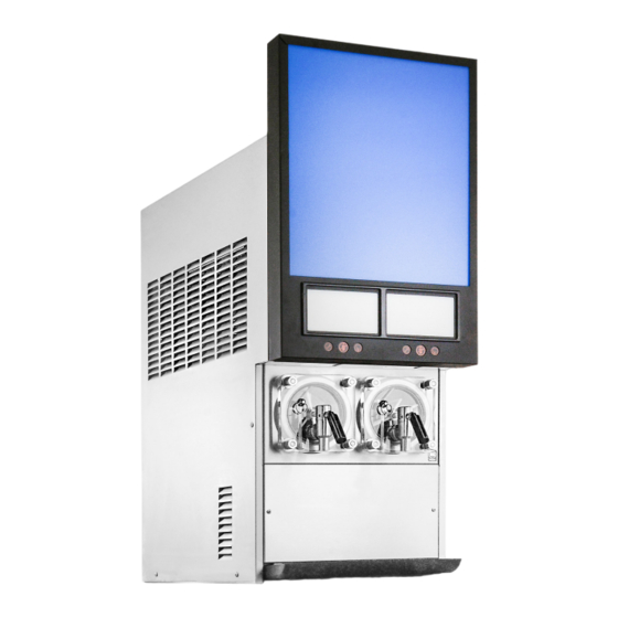
Viper Installation, Service & Decommissioning Manual CONTROL PANEL OVERVIEW Behind the merchandiser is the control panel which includes the LCD display, shown in Figure 14. This panel controls all the functions of the unit including defrost cycles, viscosity control, sensing of supply pressures and the incoming line voltage as well as other functions and features. -
Page 25: Setting The System Options
Viper Installation, Service & Decommissioning Manual Figure 17. From this screen, all the other screens may be accessed. The following procedures are required for initial setup of the unit. • Set the Options • Set the Clock • Set the Sleep and Wake Times •... - Page 26 Viper Installation, Service & Decommissioning Manual Setting the Clock Highlight the CLOCK SETUP field from the Select menu, shown in Figure 19. This displays the Clock Setup menu, shown in Figure 20. To set the time, perform the procedure in Table 11. Table 11.
- Page 27 Viper Installation, Service & Decommissioning Manual Setting Daylight Savings Time Once the date and time are set properly, the daylight savings time settings can be done. Display the Daylight Savings Time menu (Figure 21.) by pressing the DST button at the bottom of the display. To set daylight savings time, perform the procedure in Table 13. Table 13.
- Page 28 Viper Installation, Service & Decommissioning Manual Figure 22. Table 14. Option Button 2 Button 3 Button 4 Button 5 Temp Format Date Format EURO Time Format 12 HR 24 HR POS Lighting ALWAYS SLEEP #1 SYRUP TYPE FCB-L FUB-L #X SYRUP TYPE FCB-L FUB-L When all the options are set to the desired settings for the unit, press the BACK button to store these settings and return to the Select...
- Page 29 Viper Installation, Service & Decommissioning Manual Setting Defrost Lockout From the Barrel Status menu, shown in Figure 17. press the MENU button and then press the SETUP button to display the Setup menu. Use the up and down arrows on the right of the control to highlight the Events Setup menu, then press GO to enter the menu (Figure 23.).
- Page 30 Viper Installation, Service & Decommissioning Manual NOTE: Setting the wake up time ahead of the sleep time on a given day causes the unit to go into the sleep mode for a week unless the operator initiates a manual wake up. Table 16.
- Page 31 Viper Installation, Service & Decommissioning Manual Figure 24. When the viscosity settings are complete, press the BACK button to save the settings and return to the Select menu, shown in Figure 19. NOTE: Refer to the service manual for other controller functions and features. Publication Number: 620073146SER - 28 - ©...
-
Page 32: Commissioning The Unit
Viper Installation, Service & Decommissioning Manual COMMISSIONING THE UNIT OCATION This appliance is not intended for use by persons (including children) with reduced physical, sensory or mental capabilities, or lack of experience and knowledge, unless they have been given supervision or instruction concerning use of the appliance by a person responsible for their safety. -
Page 33: Pressurizing The Co
Viper Installation, Service & Decommissioning Manual Pressurizing the CO System The Viper unit is designed to operate on a CO input pressure of 75 ±1 psig. If the installation location has either an independent tank and regulator or a bulk CO supply that feeds more than one machine, a shutoff valve and secondary regulator must be placed in the line from the bulk supply to the Viper unit to reduce the CO pressure at the unit to 75 ±1 psig. -
Page 34: Pressurizing The Syrup System
Viper Installation, Service & Decommissioning Manual Pressurizing the Syrup System Perform the procedure in Table 21. to pressurize the syrup system. Table 21. Step Action Slowly turn on the CO regulator for the syrup BIB pumps to avoid damaging them and set them so there is 75 psig, no lower syrup pressure at the unit. - Page 35 Viper Installation, Service & Decommissioning Manual Table 22. Step Action Again use the up and down arrows to select the barrel you wish to perform BRIX NOTE: Pressing CANCEL will stop the process. Locate the appropriate barrel sample tube and hold a cup under it. Open the cap at the end of the sample tube.
- Page 36 Viper Installation, Service & Decommissioning Manual Adjusting BRIX Level If the BRIX reading is out of its proper range, the syrup level should be adjusted to bring BRIX into the proper range. NEVER change the WATER FLOW CONTROL setting to adjust BRIX. The syrup flow control adjustment valve is shown in Figure 28. Perform the procedure in Table 23.
-
Page 37: Filling The Barrels
Viper Installation, Service & Decommissioning Manual Figure 29. Filling the Barrels Once the barrels have been BRIXed and purged, they may be filled with product. This is accomplished by going to the Barrel Maintenance menu and pressing the FILL button. This starts the fill process for the highlighted barrel. As the barrel fills, the barrel pressure sensor shuts off the barrel at a pressure of 28 psi. - Page 38 Viper Installation, Service & Decommissioning Manual Table 24. Step Action Procedure From the Maintenance menu (Figure 31.), open the Set barrel for Motor Type Motor Setup menu, shown in Figure 30. Use the Up and Down arrows to highlight the desired Select the barrel barrel Select the proper motor...
-
Page 39: Security Menu
Viper Installation, Service & Decommissioning Manual Security Menu The security is enabled at the factory before shipping the Unit. It is recommended that security be remains enabled after installation. Figure 32. Security Disabling: System security is located on the System menu. It allows a supervisor or service technician to keep unauthorized personnel from accessing the Maintenance menu. -
Page 40: Troubleshooting
Viper Installation, Service & Decommissioning Manual TROUBLESHOOTING Problem Probable Cause Remedy Unit will not run. Unit not plugged in Plug in unit. Circuit breaker Reset/replace circuit breaker “Sleep” display on Barrel Sta- Sleep time set Check programming Clock incorrectly set Check programming tus menu No or incorrect wake up... -
Page 41: Specifications
Viper Installation, Service & Decommissioning Manual SPECIFICATIONS Line Voltage: ................... . . 215-245VAC Max. - Page 42 Viper Installation, Service & Decommissioning Manual Table 26. Recommended Syrup Pump Pressure Settings for Various Line Runs BIB Pump Set Pressure (psi) Length of Run (ft) Publication Number: 620073146SER © 2022, Marmon Foodservice Technologies Inc. - 39 -...
- Page 43 Viper Installation, Service & Decommissioning Manual ( BLANK ) Publication Number: 620073146SER - 40 - © 2022, Marmon Foodservice Technologies Inc.
- Page 44 Viper Installation, Service & Decommissioning Manual VIPER E 2 FLAVOR, R-454C SERVICE PROCEDURES Publication Number: 620073146SER © 2022, Marmon Foodservice Technologies Inc. - 41 -...
- Page 45 Viper Installation, Service & Decommissioning Manual ( BLANK ) Publication Number: 620073146SER - 42 - © 2022, Marmon Foodservice Technologies Inc.
-
Page 46: Introduction
Viper Installation, Service & Decommissioning Manual INTRODUCTION ANUAL VERVIEW The organization of this manual allows the user to scan quickly to the subject of interest along the left side of a page and to read the detail about the subject or procedure on the right side of the page. The manual provides the detail needed for newcomers to the industry while allowing experienced technicians to skip over the details and move quickly through the material. -
Page 47: Dispensed Product Conditions
Viper Installation, Service & Decommissioning Manual ISPENSED RODUCT ONDITIONS Overrun, as Applied to Carbonated Beverages Overrun Definition Overrun is defined as product expansion that takes place in the frozen carbonated drink. It is caused primarily by CO breakout and secondarily by freezing. Overrun is a Variable The percentage or degree of overrun depends on a number of factors. -
Page 48: System Overview
Viper Installation, Service & Decommissioning Manual SYSTEM OVERVIEW NTRODUCTION The Viper unit consists of the following systems and hardware: Multiple freeze barrels, each containing an internal scraper bar driven by an AC motor. A refrigeration system and an intelligent, hot gas defrost system. The components are enclosed in a powder-coated steel frame to prevent corrosion. - Page 49 Viper Installation, Service & Decommissioning Manual Figure 33. Viper System 2-Barrel Refrigeration-R454C Schematic Publication Number: 620073146SER - 46 - © 2022, Marmon Foodservice Technologies Inc.
- Page 50 Viper Installation, Service & Decommissioning Manual Figure 34. Viper 2-Barrel Wiring Diagram (W/Transducer) Publication Number: 620073146SER © 2022, Marmon Foodservice Technologies Inc. - 47 -...
-
Page 51: Co2 System
Viper Installation, Service & Decommissioning Manual *An overall schematic of the delivery systems contained in the unit are shown in Figures 36 and 37. The CO system interacts with both the water and syrup systems. It provides pressure and carbonation for the syrup/water product mix. System A CO tank or bulk CO... - Page 52 Viper Installation, Service & Decommissioning Manual Table 27. provides guidelines for machine settings based on general syrup type. Several factors, including syrup formulation, level of citric acids, etc, will impact settings. These settings are to provide initial adjustments to achieve product overruns in the 80-120% range.
- Page 53 Viper Installation, Service & Decommissioning Manual Figure 36. 2-Barrel System Schematic Publication Number: 620073146SER - 50 - © 2022, Marmon Foodservice Technologies Inc.
-
Page 54: Water System
Viper Installation, Service & Decommissioning Manual Water System Incoming water flows to a water pressure regulator that is preset to 30 psig. It flows through the water booster pump, to the regulator and through a sold-out switch. Once through the boost pump, the water supply is split to each barrel and is fed to the water flow controls. From the flow rate control, the water passes through a single ball check valve and mixes with the syrup in a Y-fitting for injection into the freeze barrel. -
Page 55: Control Panel Buttons
Viper Installation, Service & Decommissioning Manual Menu Display Area Menu Buttons Figure 37. Control System Display Control Panel Buttons The second area are the buttons and arrows located across the bottom and on the right side of the control panel. There are up to five buttons and four directional arrows that may be used on a screen to activate and control various the functions of the system. - Page 56 Viper Installation, Service & Decommissioning Manual Figure 38. Software Structure Publication Number: 620073146SER © 2022, Marmon Foodservice Technologies Inc. - 53 -...
-
Page 57: Control Panel Menu Descriptions
Viper Installation, Service & Decommissioning Manual ONTROL ANEL ESCRIPTIONS The following section describes the information displayed on each control panel menu and the interactions and settings that are controlled by that menu. System Menus The system menu structure allows the user to control the unit through the control panel. Operational settings, optional parameters, troubleshooting and error information are controlled through this menu system. -
Page 58: Unit Data Menu
Viper Installation, Service & Decommissioning Manual When the Select menu is displayed, the Unit Data is highlighted. To access the Unit Data menu, press the GO button. Refer to Table 29, the Select menu, for button functions. Table 29. Button Description BACK Returns the display to the Barrel Status menu... - Page 59 Viper Installation, Service & Decommissioning Manual Table 31. Error Type Description System A System error displays the same information across all barrels in the unit. Barrel A Barrel error is limited to a specific barrel A Limp error is an error that doesn’t prevent the unit from operating, but lim- Limp its functionality.
-
Page 60: Error Log Menu
Viper Installation, Service & Decommissioning Manual Table 32. Displayed Action Type Description Message COM ERR STAT Limp Communications error, the system continues to run. The unit is experiencing voltage greater than 260VAC. System is enabled when line HIGH VOLTAGE System voltage drops below 260VAC for two minutes. -
Page 61: Setup Menu
Viper Installation, Service & Decommissioning Manual Setup Menu The Setup menu provides the means to change various settings to local preferences, such as time, date and temperature formats. It also allows the user to adjust the unit for the type of syrup being served in each barrel. To access the Setup menu from the Barrel Status menu, press the MENU button. -
Page 62: Setting The Clock
Viper Installation, Service & Decommissioning Manual Table 35. Button Description BACK Returns the display to the Select menu CLOCK Highlighted to indicate that the Clock menu is displayed Opens the Daylight Savings Time menu Decrements the highlighted field Increments the highlighted field Setting the Clock To set the time, perform the procedure in Table 36. - Page 63 Viper Installation, Service & Decommissioning Manual NOTE: Default daylight savings settings are for the U.S. Figure 46. Daylight Savings Setup Screen Table 38. Button Description BACK Returns the display to the Select menu CLOCK Opens the Clock menu Highlighted to indicate DST menu Decrements the highlighted field by one increment Increments the highlighted field by one increment Table 39.
-
Page 64: Events Setup Menu
Viper Installation, Service & Decommissioning Manual The Events Setup menu, shown in Figure 47, allows the user to set sleep periods for the unit and to lock out the defrost cycle during peak busy times. Sleep periods and defrost lockouts may be programmed for any day of the week or for all days of the week, depending on business requirements. -
Page 65: Setting Defrost Lockout
Viper Installation, Service & Decommissioning Manual Table 41. Step Action Procedure Select SLEEP Use the up and down arrows to highlight SLEEP. Use the left and right arrows to select the hour field and press the + or - buttons to Set hour field change the hour. -
Page 66: Viscosity Setup Menu
Viper Installation, Service & Decommissioning Manual Viscosity Setup Menu The viscosity maintained in the freeze barrels depends on the type of product being served. Some products are served best at a higher viscosity, while others require a lower viscosity for best quality. The Viscosity menu, shown in Figure 48, allows the user to adjust the viscosity in each barrel to the optimum setting for each type of syrup. -
Page 67: Setting The Temperature Format
Viper Installation, Service & Decommissioning Manual Table 44. Option Button 2 Button 3 Button 4 Button 5 ° ° Temp Format Date Format EURO Time Format 12 HR 24 HR POS Lighting ALWAYS SLEEP #1 SYRUP TYPE FCB-L FUB-L #X SYRUP TYPE FCB-L FUB-L When all the options are set to the desired settings for the unit, press the BACK button to store these settings and return to the... -
Page 68: Barrel Maintenance Menu
Viper Installation, Service & Decommissioning Manual Figure 50. Select Screen Barrel Maintenance Menu The Barrel Maintenance menu, shown in Figure 51, allows the service technician to clean, rinse and sanitize the system on a barrel by barrel basis. The barrel must be OFF in order to perform the barrel maintenance functions. As a warning to the technician, the “Do Not Drink”... -
Page 69: Filling A Barrel
Viper Installation, Service & Decommissioning Manual Filling a Barrel Table 46. Step Action Procedure From the Select menu (), open the Barrel Maintenance Fill a barrel menu, shown in Figure 51. Use the Up and Down arrows to highlight the desired Select the barrel barrel Press the FILL button at the bottom of the display to fill... -
Page 70: Manual Diagnostic Menu
Viper Installation, Service & Decommissioning Manual Table 48. Step Action Procedure Repeat the Purge procedure in Table 45 to empty the Complete the procedure barrel. Manual Diagnostic Menu The Manual Diagnostic menu, shown in Figure 52, is used for troubleshooting and testing the system on a component basis. It allows the service technician to turn individual components of the system on and off for troubleshooting purposes. -
Page 71: Brix Setup Menu
Viper Installation, Service & Decommissioning Manual cycles. Pressing the BACK button returns to the Choose menu and saves the changes. The description of each item in the Totals list is shown in Table 50. To move between one set of barrel parameters and the next, press the Right or Left arrow keys. This highlights the first entry of the second barrel, etc. - Page 72 Viper Installation, Service & Decommissioning Manual Table 51. Step Action Procedure From the Setup screen, open the BRIX Setup screen, shown in Figure 54. Set barrel for BRIX Use the Up and Down arrows to highlight BRIX SETUP. Press the GO button at the bottom of the display.
- Page 73 Viper Installation, Service & Decommissioning Manual Splash panel cladding Drip tray cladding Splash Panel Retaining Screws Figure 56. For Carbon Splash Panel Mounting Screws Product Product Supply Supply Valve Valve Barrel 1 Barrel 2 Flow Flow Controls Controls Barrel 1 Barrel 2 Valves shown in BARREL position w/ Splash Panel Removed Figure 57.
-
Page 74: Motor Setup Menu
Viper Installation, Service & Decommissioning Manual Motor Setup Menu Motor setup is initially done at the factory and does not need to be changed unless a barrel motor or barrel components are replaced, adjusted or removed and reinstalled. This menu allows you to select different motor types for each barrel in the unit and run the calibration procedure on that motor. -
Page 75: Calibrating A Motor
Viper Installation, Service & Decommissioning Manual Calibrating a Motor Calibration of motors is typically required when a motor or any associated barrel components (i.e., scrapper blades, seal, faceplate, etc.) is removed or replaced. Calibration establishes a new baseline for the motor assembly. This allows the system to determine proper viscosity settings for the new motor. -
Page 76: Security
Viper Installation, Service & Decommissioning Manual Table 56. Display Description SECURITY This selection allows the user to turn security on or off. CMP #X SENSORS This selection allows the user to choose which pressure sensors are read for the compressor. Option Button 2 Button 3... - Page 77 Viper Installation, Service & Decommissioning Manual NOTE: If a pressure sensor is open, the pressure reading is 386 PSIG. LINE VOLTAGE: 229 UNIT LINE FREQUENCY: 60 DATA LOW PSIG #1: HIGH PSIG #1: 12:51P MAR 04 BACK BRL UNIT Figure 62. Unit Data Screen Publication Number: 620073146SER - 74 - ©...
-
Page 78: Operation
Sleep Mode Recommendations Cornelius recommends programming a sleep period for the machine during any amount of time over 3 hours that the unit is not used. This increases the life of the machine and reduces energy consumption. -
Page 79: Viscosity Setting
As the ice crystal size increases, however, there is potential for product quality to diminish. Cornelius recommends that the viscosity settings be set at the lowest possible setting to achieve the desired drink quality. In most typical installations using a sugar-based syrup, acceptable drink quality can be achieved by programmed viscosity settings in the range of 3-5 for Viper. -
Page 80: Preventative Maintenance
Viper Installation, Service & Decommissioning Manual PREVENTATIVE MAINTENANCE UMMARY There are no daily maintenance procedures required on the Viper unit other than normal cleanup of spills or overspray and emptying the drip tray. Normal equipment maintenance intervals are listed in Table 59 It is recommended that a preventa- tive maintenance procedure be performed every twelve (12) months. -
Page 81: Annual Maintenance
Viper Installation, Service & Decommissioning Manual Table 60 Step Action Open the merchandiser Remove the filter, shown in Figure 63, by grasping the two tabs and sliding it straight out the front of the unit. Wash the filter with clean water. Shake out the excess water. Reinstall the air filter. -
Page 82: Cleaning The Syrup Connections
Viper Installation, Service & Decommissioning Manual Table 61 Step Action Replace the blade assembly and bushings (PN 2392) onto the motor shaft in the bar- rel. Re-install the faceplate and replace the four (4) mounting nuts. Hand tighten the nuts until the faceplate makes contact with the gasket, then use a wrench to tighten the nuts an additional 1/4 turn. -
Page 83: Suggested Sanitizers
Viper Installation, Service & Decommissioning Manual Figure 64. Self-Closing Dispensing Valve WARNING: In Step 1, when defrost is complete, disconnect electrical power from the unit. Failure to disconnect the power could result in serious injury, death, or equipment damage. Table 63 Step Action... -
Page 84: Suggested Sanitizers
Viper Installation, Service & Decommissioning Manual Table 63 Step Action Assemble the dispensing valve. Rinse them with warm water, and place them on clean paper towels. Lubricate the caged o-ring. Carefully install the caged o-ring onto the valve from the straight end (opposite tapered end). -
Page 85: Emptying A Barrel
Viper Installation, Service & Decommissioning Manual WARNING: In Step 1, when defrost is complete, disconnect electrical power from the unit. Failure to disconnect the power could result in serious injury, death, or equipment damage. Table 64. Step Action Defrost freeze cylinders, shut unit down, disconnect electrical power from Unit. Perform the procedure in Table 65 to empty the barrels. -
Page 86: Flushing The System Of Syrup
Viper Installation, Service & Decommissioning Manual Flushing the System of Syrup After emptying the barrel, the barrel should be flushed of product before proceeding with the sanitizing procedure. Per- form the procedure in Table 8. Table 66. Step Action Fill a clean 5-gallon pail with plain water. Connect a sanitizing fitting (p/n cc 28688) to the BIB connector. -
Page 87: Flushing The System
Viper Installation, Service & Decommissioning Manual Flushing the System Flush the wash water from the system by performing the procedure in Table 68. CAUTION: Flush the system thoroughly, residual sanitizing solution left in the system may create a health hazard. Table 68. - Page 88 Viper Installation, Service & Decommissioning Manual WARNING: In Step 1, disconnect electrical power from the unit. Failure to disconnect the power could result in serious injury, death, or equipment damage. Table 69 Step Procedure Disconnect power from the unit. Turn off and disconnect the water supply to the unit.
-
Page 89: Component Replacement
Viper Installation, Service & Decommissioning Manual COMPONENT REPLACEMENT The following are procedures for servicing the major components of the Viper system. ARREL OTOR EPLACEMENT The barrel motor seal is typically replaced during the annual preventative maintenance procedure. The seal location is shown in Figure 67. -
Page 90: Installing A New Seal
Viper Installation, Service & Decommissioning Manual Installing a New Seal Perform the procedure in Table 71, referring to Figure 67 and Figure 68 to replace the barrel seal with a new seal. NOTE: When installing a new seal, never use oil or silicon based lubricants. This can cause the new seal to rotate and leak! Table 71 Step... -
Page 91: Motor Seal Leak Test
Viper Installation, Service & Decommissioning Manual Seal Spacer Figure 69. Side View of Seal and Spacer on Motor Shaft Motor Seal Leak Test After replacing the motor seal, it is advisable to test the seal under pressure before refilling the barrel with product. Per- form the procedure in Table 72 to verify that the seal is installed properly and not leaking. -
Page 92: Barrel Motor Replacement
Viper Installation, Service & Decommissioning Manual ARREL OTOR EPLACEMENT The barrel motor does not require any special alignment when being replaced. It mounts on four (4) bolts. These bolts are screwed into threaded bosses in the foam pack barrel assembly, as shown in Figure 70. To replace a barrel motor, perform the procedure in Table 73 Barrel Motor Mounting... -
Page 93: Water Pump Replacement
Viper Installation, Service & Decommissioning Manual WARNING: In Step 1, disconnect electrical power from the unit. Failure to disconnect the power could result in serious injury, death, or equipment damage. Table 74 Step Action Disconnect power from the unit. Remove the rear cover. Disconnect the spade clips from the defective capacitor. -
Page 94: Co2 Shutoff Solenoid Replacement
Viper Installation, Service & Decommissioning Manual Table 75 Step Action Reverse the procedure to install the new pump. HUTOFF OLENOID EPLACEMENT The CO2 shutoff valves and solenoids, shown in Figure 73, are located near the center of the unit and are mounted on a bracket to the bottom of the chassis. -
Page 95: Syrup And Water Shutoff Solenoid Replacement
Viper Installation, Service & Decommissioning Manual Syrup and Water Shutoff Solenoid Replacement The syrup and water shutoff valves and solenoids are mounted on a single bracket, as shown in Figure 74. Perform the pro- cedure in Table 77 to replace the valves. Water Shutoff Valves &... -
Page 96: Co2 Regulator Replacement
Viper Installation, Service & Decommissioning Manual EGULATOR EPLACEMENT The CO regulators are located at the center of the unit in back of the access panel, as shown in Figure 75. To replace the regulators, perform the procedure in Table 78. CO2 Regulators Barrel 1 Barrel 2... -
Page 97: Condenser Fan Motor Replacement
Viper Installation, Service & Decommissioning Manual ONDENSER OTOR EPLACEMENT The fan motor is located on the top of the unit, as shown in Figure 76. If the motor needs replacement, perform the proce- dure in Table 79 to remove and reinstall a motor. Locking Locking Nuts... -
Page 98: Hot Gas Solenoid Replacement
Reverse the procedure to install the new compressor. Replace the dryer. Evacuate the system and recharge it according to the Cornelius nameplate on the unit. Replace the side panels and rear cover. Reconnect power to the unit and test the unit. -
Page 99: Liquid Line Solenoid Replacement
Viper Installation, Service & Decommissioning Manual IQUID OLENOID EPLACEMENT The liquid line valves and solenoids, shown in Figure 78, are located near the center of the unit on the right and left sides. Whenever a liquid line valve and solenoid is replaced, the dryer should be replaced at the same time. Liquid Line Solenoid Figure 78. -
Page 100: Water Pressure Switch Replacement
Viper Installation, Service & Decommissioning Manual WARNING: In Step 1, disconnect electrical power from the unit. Failure to disconnect the power could result in serious injury, death, or equipment damage. Table 83. Step Action Disconnect power to the unit Remove the appropriate side panel. Turn off the syrup supply to the unit. -
Page 101: Display Board Replacement
Viper Installation, Service & Decommissioning Manual Table 84. Step Action Reverse the procedure to install the new switch. Restore the water supply and check for leaks. Check to ensure that the new switch is working properly. ISPLAY OARD EPLACEMENT When replacing or testing electronic components, be sure to wear a static strap that is connected to a chassis ground. This protects the electronic components from any static charge while working on the unit. -
Page 102: Backward/Forward Compatibility With Older Software Versions
Viper Installation, Service & Decommissioning Manual WARNING: In Step 1 in Table 86, disconnect electrical power from the unit. Failure to disconnect the power could result in serious injury, death, or equipment damage. Table 86. Step Action Disconnect power from the unit. Connect a static strap to your wrist and any convenient chassis ground on the unit. -
Page 103: Motor Board Replacement
Viper Installation, Service & Decommissioning Manual The foreign language chips are software version dependent. Part numbers for software version 3.0 chips have the base number of 629096931 followed by an alpha suffix designating the language type. The motor control boards and the main status board will still operate with either version 2.x or 3.x software of UI and IO board. -
Page 104: Troubleshooting
Viper Installation, Service & Decommissioning Manual TROUBLESHOOTING ROUBLESHOOTING THE YSTEM Table 56. Problem Probable Cause Remedy Unit will not run. A. Unit not plugged in. A. Plug in unit. B. Circuit breaker. B. Reset/replace circuit breaker C. No power at L1 or L2 on contactor. C. - Page 105 Viper Installation, Service & Decommissioning Manual Table 57. Restricted Air Flow A. Dirty filter. A. Clean filter. B. Dirty condenser. B. Clean condenser. C. Damaged fins. C. Repair/replace if necessary. D. Not enough “clearance” around unit. D. Ensure proper spacing around unit. Fan Motor A.
- Page 106 Viper Installation, Service & Decommissioning Manual VIPER E 2 FLAVOR, R-454C DECOMMISSIONING PROCEDURES Publication Number: 620073146SER © 2022, Marmon Foodservice Technologies Inc. - 103 -...
-
Page 107: Decommissioning Procedure
Viper Installation, Service & Decommissioning Manual DECOMMISSIONING PROCESS Before carrying out this procedure, it is essential that the technician is completely familiar with the equipment and all its detail. It is recommended good practice that all refrigerants are recovered safely. Prior to the task being carried out, an oil and refrigerant sample shall be taken in case analysis is required prior to re-use of recovered refrigerant. -
Page 108: Information On Correct Working Procedures
Viper Installation, Service & Decommissioning Manual The recovered refrigerant shall be returned to the refrigerant supplier in the correct recovery cylinder, and the relevant waste transfer note arranged. Do not mix refrigerants in recovery units and especially not in cylinders. If compressors or compressor oils are to be removed, ensure that they have been evacuated to an acceptable level to make certain that FLAMMABLE REFRIGERANT does not remain within the lubricant. - Page 109 Viper Installation, Service & Decommissioning Manual Discharge capacitors in a way that won’t cause any spark, using a Supco CapDis tool. (The standard procedure to short circuit the capacitor terminals usually creates sparks.) Reassemble sealed enclosures accurately. If seals are worn, replace them. Check safety equipment before putting into service.
-
Page 110: Disposal
Viper Installation, Service & Decommissioning Manual G) Remove parts to be replaced by cutting or brazing. H) Purge the braze point with nitrogen during the brazing procedure required for repair. I) Carry out a leak test before charging with refrigerant. When FLAMMABLE REFRIGERANTS are used: A) Evacuate the refrigerant circuit. - Page 111 Cornelius Inc. www.cornelius.com...
Need help?
Do you have a question about the VIPER E 2 FLAVOR and is the answer not in the manual?
Questions and answers