Table of Contents
Advertisement
Quick Links
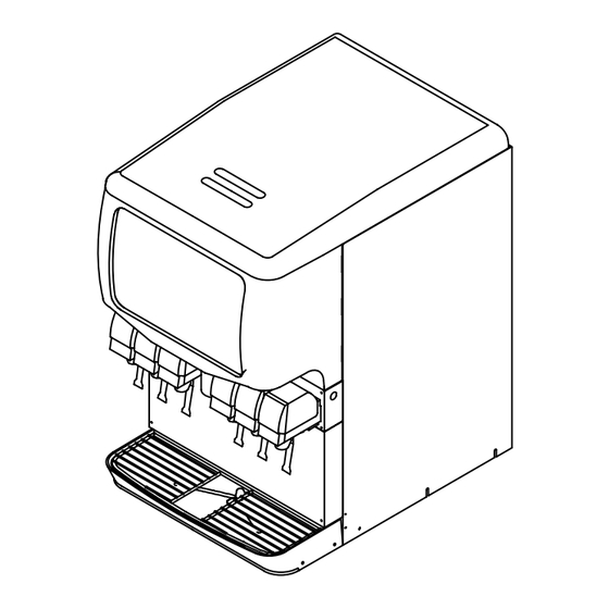
ICE/BEVERAGE DISPENSER
MODELS: ENDURO-150 (SIX VALVE)
Installation Manual
IMPORTANT:
TO THE INSTALLER.
It is the responsibility of
the Installer to ensure that
the water supply to the
dispensing equipment is
provided with protection
against backflow by an air
gap as defined in
ANSI/ASME A112.1.2-1979;
or an approved vacuum
breaker or other such
method as proved effective
by test.
Water pipe connections
and fixtures directly
connected to a potable
water supply shall be
sized, installed, and
maintained according to
Federal, State, and Local
Codes.
Part No. 91971RINS
Release Date: February 24, 2004
Revised: November 18, 2005
Revision: C
THIS DOCUMENT CONTAINS IMPORTANT INFORMATION
This Manual must be read and understood before installing or operating this equipment
©
IMI CORNELIUS INC; 2004–2005
IMI CORNELIUS INC
www.cornelius.com
PRINTED IN U.S.A
Advertisement
Table of Contents

Related Manuals for Cornelius ENDURO-150


Summary of Contents for Cornelius ENDURO-150
- Page 1 IMI CORNELIUS INC www.cornelius.com ICE/BEVERAGE DISPENSER MODELS: ENDURO-150 (SIX VALVE) Installation Manual IMPORTANT: TO THE INSTALLER. It is the responsibility of the Installer to ensure that the water supply to the dispensing equipment is provided with protection against backflow by an air gap as defined in ANSI/ASME A112.1.2-1979;...
-
Page 2: Table Of Contents
TABLE OF CONTENTS SAFETY PRECAUTIONS ........... DESCRIPTION . -
Page 3: Safety Precautions
SAFETY PRECAUTIONS This ice dispenser has been specifically designed to provide protection against personal injury and eliminates contamination of ice. To ensure continued protection and sanitation, observe the following: ALWAYS: disconnect power to the dispenser before servicing or cleaning. NEVER: place hands inside of hopper or gate area without disconnecting power to the dispenser. Agitator rotation occurs automatically when dispenser is energized! ALWAYS: be sure the removable lid is properly installed to prevent unauthorized access to the hopper interior and possible contamination of the ice. -
Page 4: Description
DESCRIPTION The “ENDURO” series of ice dispensers solves your ice and beverage service needs in a sanitary, space saving, economical way. Designed to be manually filled with ice from any remote ice-making source, these dispensers will dispense cubes (up to 1-1/4” in size), cubelets and hard-chipped or cracked ice; and, in addition, several flavors of post-mix beverages. -
Page 5: Installation Instructions
INSTALLATION INSTRUCTIONS IMPORTANT: TO THE INSTALLER. It is the responsibility of the Installer to ensure that the water supply to the dispensing equipment is provided with protection against backflow by an air gap as defined in ANSI/ASME A112. 1.2-1979; or an approved vacuum breaker or other such method as proved effective by test. -
Page 6: Figure 1. Mounting Template
7/16 DIA. HOLE (4 PLCES) 1 13/16 18 7/16 1 5/16 21 1/4 18 5/8 OPENING 23 1/16 30 11/16 REMOVABLE SINK Z STYLE TO FRONT OF DRIP TRAY ON COUNTER 6 11/16 8 5/8 3 1/2 TO FRONT TOP OF DRIP TRAY RECOMMENDED COUNTER OPENING SIZE 9”... -
Page 7: Figure 2. Drip Tray Drain Assembly
SOLVENT BOND HOSE CLAMP DRIP TRAY DRAIN FITTING COUPLING 3/4 SOCKET X 3/4 FPT BARB ADAPTER 1 BARB X 3/4 MPT DRAIN LINE 1-IN. I.D. PLASTIC TUBING (6 FT) WITH INSULATION FIGURE 2. DRIP TRAY DRAIN ASSEMBLY 91971RINS... -
Page 8: Ice Diverter Kit 02394
ICE DIVERTER KIT 02394 NOTE: For dispensing Scotsman, Wilshire, and Hoshizaki compressed ice cubes: 1. Disconnect power to dispenser. 2. Remove Merchandiser from dispenser. 3. Remove ice chute and discard gate restrictor. 4. Install ice diverter on gate mounting plate as shown below. 5. -
Page 9: Gate Restrictor Plate
GATE RESTRICTOR PLATE CAUTION: Disconnect power to dispenser before installing, removing or adjusting restrictor. ADJUSTMENT INSTALL PLATE ON STUDS AS SHOWN FIGURE 4. GATE RESTRICTOR PLATE ADJUSTMENT This plate may be adjusted as shown to reduce or increase the dispensing rate of ice, especially desirable when using glasses or other containers with small openings. -
Page 10: Plumbing Diagram (Bc Modles)
PLUMBING DIAGRAM (BC MODLES) COLDPLATE INLET CONNECTIONS FLAVOR MODULE OPTION FAUCETS VIEWED FROM FRONT OF UNIT FIGURE 5. PLUMBING DIAGRAM (BC MODEL) 91971RINS... -
Page 11: Plumbing Diagram (B Models)
PLUMBING DIAGRAM (B MODELS) FLAVOR MODULE FAUCETS VIEWED FROM FRONT OF UNIT FIGURE 6. PLUMBING DIAGRAM (B MODEL) 91971RINS... -
Page 12: Troubleshooting
TROUBLESHOOTING IMPORTANT: Only qualified personnel should service internal components or electrical wiring. WARNING: If repairs are to be made to a product system, remove quick disconnects from the applicable product tank, then relieve the system pressure before proceeding. If repairs are to be made to the CO system, stop dispensing, shut off the CO supply, then relieve the... -
Page 13: Beverage Not Sweet Enough
Trouble Probable Cause BEVERAGE NOT SWEET ENOUGH. Empty syrup tank. Faucet brix requires adjusting. BEVERAGES NOT COLD (UNITS WITH BUILT-IN Unit standing with no ice in hopper – no ice in COLD PLATE). cold plate cabinet. FLAVOR SYRUPS DO NOT DISPENSE No 24 volt power to PC board. -
Page 14: Wiring Diagram (120 V Unit)
WIRING DIAGRAM (120 V UNIT) FIGURE 7. WIRING DIAGRAM (120 V UNIT) 91971RINS... -
Page 15: Wiring Schematic (120 V Unit)
WIRING SCHEMATIC (120 V UNIT) TIMER RECTIFIER MOTOR HEATER AGITATOR MOTOR N.O. VEND SWITCH N.C. CAPACITOR GATE SOLENOID BALLAST OPTIONAL LIGHT STARTER OPTIONAL BEVERAGE TRANSFORMER OPTIONAL FLAVOR VLVS OPTIONAL ICE LEVEL KEYPAD BOARD SOLENOIDS OPTIONAL OPTIONAL BEVERAGE BEVERAGE VALVES VALVES BEVERAGE PANEL FIGURE 8. -
Page 16: Wiring Diagram (220-240 V Unit)
WIRING DIAGRAM (220–240 V UNIT) FIGURE 9. WIRING DIAGRAM (220–240 V UNIT) 91971RINS... -
Page 17: Wiring Schematic (220-240 V Unit)
WIRING SCHEMATIC (220–240 V UNIT) 220–240V EMI FILTER LINE FILTER TIMER RECTIFIER MOTOR HEATER POWER SWITCH AGITATOR MOTOR N.O. VEND SWITCH N.C. GATE SOLENOID OPTIONAL BALLAST OPTIONAL LIGHT OPTIONAL STARTER OPTIONAL BEVERAGE TRANSFORMER OPTIONAL FLAVOR VLVS BOARD OPTIONAL ICE LEVEL KEYPAD SOLENOIDS OPTIONAL... -
Page 18: Warranty
IMI Cornelius Inc. warrants that all equipment and parts are free from defects in material and workmanship un- der normal use and service. For a copy of the warranty applicable to your Cornelius, Remcor or Wilshire prod- uct, in your country, please write, fax or telephone the IMI Cornelius office nearest you. Please provide the equipment model number, serial number and the date of purchase. - Page 19 IMI CORNELIUS INC. 91971RINS...
Need help?
Do you have a question about the ENDURO-150 and is the answer not in the manual?
Questions and answers