
Related Manuals for JAI LQ-401CL


Summary of Contents for JAI LQ-401CL
- Page 1 User's Manual LQ-401CL RGB Color & NIR 4CMOS Line Scan Camera Document Version:1.2 LQ-401CL_Ver.1.2.Dec2014 1060E-1409...
- Page 2 JAI Ltd., Japan and may only be used by the purchasers of the product. JAI Ltd., Japan makes no warranty for the use of its product and assumes no responsibility for any errors which may appear or for damages resulting from the use of the information contained herein.
- Page 3 LQ-401CL Supplement The following statement is related to the regulation on “ Measures for the Administration of the control of Pollution by Electronic Information Products “ , known as “ China RoHS “. The table shows contained Hazardous Substances in this camera.
-
Page 4: Table Of Contents
LQ-401CL - Table of contents – General ......................6 Camera composition ..................6 Main features ....................7 Locations and functions ..................8 4.1. Locations and functions ................8 4.2. Rear Panel ....................9 Connectors and pin assignment ................10 5.1. - Page 5 Command WB – White Balance ..............52 Serial communication and command list ............... 53 8.1. Serial communication ................. 53 8.2. Command list ..................54 Camera Control Tool for LQ-401CL ..............61 9.1. Software Install ..................61 9.2. Open the Control Tool ................61 9.3.
- Page 6 LQ-401CL Exportation ....................71 References ....................71 Change history ..................... 72 User's Record ....................... 73...
-
Page 7: General
LQ-401CL General The LQ-401CL is a 4CMOS line scan camera using four 4096 pixel line sensors mounted on a prism, for the R, G, B and NIR channels. It operates with an 84 MHz pixel clock, resulting in a maximum line rate of 18,252 lines per second. -
Page 8: Main Features
LQ-401CL Main features 4CMOS line scan camera with 4096 pixel resolution Dichroic beam splitter prism to separate R,G,B and NIR wavelengths 18,252 lines per second scan rate 84 MHz pixel clock 4 x 8 bits or 4 x 10 bits output through Camera Link interface ... -
Page 9: Locations And Functions
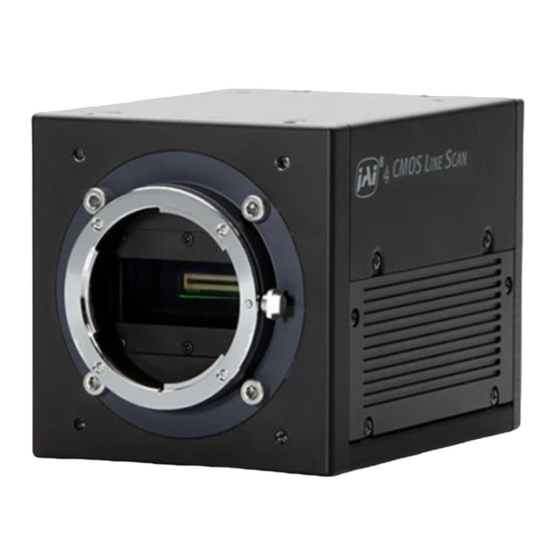
LQ-401CL Locations and functions 4.1. Locations and functions Fig. 1 Location of external features 1 Lens mount M52 mount (*1)Note) 2 Camera Link connector 1 base connector (1) (*2)Note) 3 Camera Link connector 2 medium connector (2) (*2)Note) 4 12-pin Hirose connector... -
Page 10: Rear Panel
LQ-401CL 4.2. Rear Panel ① POW ER / TRIG W . B . D C IN ② /TRIG S W 1 Fig2. Rear panel ① LED Green (Steady) Operating, but not receiving external trigger input Green (Flashing) Operating and receiving external trigger input. -
Page 11: Connectors And Pin Assignment
Cables, transmission systems and frame grabbers/acquisition boards that do not comply with the Camera Link standard may work with this camera, but JAI Camera Solutions cannot be held responsible for loss in performance or damage of equipment, including the camera. -
Page 12: Conformable Connector And Cable Assembly
(Thin diameter type) or 14B26-SZ3B-xxx-04C (High flex type), the cable length for transmission is limited. 5.3.3 Camera Link Interface (Bit allocation) The LQ-401CL follows the Camera Link standard in all respects. Out1_D9~Out1_D0 : Out1_Camera Data (Out1_D9=MSB, Out1_D0=LSB) Out2_D9~Out2_D0 : Out2_Camera Data (Out2_D9=MSB, Out2_D0=LSB) Out3_D9~Out3_D0 : Out3_Camera Data (Out3_D9=MSB, Out3_D0=LSB) Out4_D9~Out3_D0 : Out4_Camera Data (Out4_D9=MSB, Out4_D0=LSB) - Page 13 LQ-401CL Port B5 Out2_D5 Out2_D9 Tx14 Port B6 Out2_D6 × Tx10 Port B7 Out2_D7 × Tx11 Port C0 Out3_D0 Out2_D0 Tx15 Port C1 Out3_D1 Out2_D1 Tx18 Port C2 Out3_D2 Out2_D2 Tx19 Port C3 Out3_D3 Out2_D3 Tx20 Port C4 Out3_D4 Out2_D4...
-
Page 14: Camera Link Output Port
5.3.4 Camera link output port LQ-401CL handles R, G, B and NIR channels. The output ports for 8-bit and 10-bit are different. The following drawings show the default settings for the Camera Link Video Output Select (Command OS1 to OS6). Camera Link output can be configured by command OS. -
Page 15: Bit Allocation Of The Output Video
1000 Fig.9 Signals flow The LQ-401CL uses four high-performance CMOS line scan image sensors mounted on a prism block. During exposure, the incoming light is converted to electrons (electric charge) in the photodiodes (active pixels). The transfer gate controls the transfer of charge from photodiodes to the shift register. - Page 16 (the inverse of line rate). This also allows a fixed exposure time, independent of the line rate. In the LQ-401CL the exposure time can be set individually for all four channels.
-
Page 17: Key Functions
LQ-401CL Key functions Important note: LQ-400CL has many functions explained in this chapter. In order to use these functions properly and to get proper image, please follow the procedure described below. Setting procedure: 1. Set the shutter and line rate 2. -
Page 18: External Trigger
LQ-401CL 6.2.3 External Trigger The external trigger can be input through the 12-pin connector or Camera Link CC1. These cannot be used at the same time. The external trigger signal can be terminated by 75 ohms inside the camera (Refer to Chapter 4.2). -
Page 19: Gain Control
LQ-401CL Gain white balance Calculates the difference between green and red video levels, and green and blue levels, and adjusts the red and blue channels’ video level so that the video level of all three channels becomes equal. Command WB=0... - Page 20 LQ-401CL Analog Gain = LOW Analog Gain = HIGH Master Blue +6dB +20dB Master Blue +6dB +14dB +6dB -4dB +8dB +6dB +6dB -4dB +4dB +2dB -4dB -4dB Fig.13 Master gain mode with Gain Low and High 2. Individual gain mode...
-
Page 21: Black Level
LQ-401CL 6.2.6 Black level The setup level of the LQ-400CL is set at 8LSB in 4 x 8-bit output mode as the factory default setting (32LSB for 4 x 10-bit output mode) In order to adjust, the following commands are available. -
Page 22: Dsnu (Dark Signal Non-Uniformity) Correction
LQ-401CL After correction: flat response from pixel to pixel Average Fig.16 Conceptual drawing for PRNU correction (2) 6.2.8 DSNU (Dark Signal Non-Uniformity) correction DSNU (Dark Signal Non-Uniformity) is, as the name implies, a non-uniformity of offset level of each pixel, which is not dependent on the incoming light. - Page 23 LQ-401CL Shading caused by uneven illumination or transmission at the edges of the lens. Pixel response non-uniformity will be superimposed on the output signal Fig.19 Shading correction The shading correction has two ways to compensate, flat shading correction and color shading correction.
-
Page 24: Lateral Chromatic Aberration
LQ-401CL Fig.21 Color shading correction concept drawing Note: For this function, no reference value is stored in the camera. Operating procedure for individual R, ,B and NIR channel shading correction: 1. Before making adjustment, approximately 30 minutes of warm up is required. - Page 25 LQ-401CL Fig. 22 Setting screen for lateral chromatic aberration Setting procedure: Please use the following steps. 1. Chromatic Aberration Enable 2. Select Lens 1, 2 or 3 3. Set the left side pixel 4. Set the area 5. Set the second block pixel 6.
- Page 26 LQ-401CL The following is the result of a negative setting The following is the result of a positive setting. Fig. 23 Operation of the compensation Area : This command specifies the area in which pixel shifting will be applied. The image is divided into 16 blocks, with each block representing 256 pixels.
-
Page 27: Aperture Filter
LQ-401CL Note: 1) If left side pixel is set at -2 or +2, only Area and 2nd can be configured. 3rd cannot be set. 2) If left side pixel is set at -1 or +1, only Area can be configured. -
Page 28: Test Pattern Generator
LQ-401CL 1 0 2 3 1 0 2 4 1 0 2 5 1 0 2 6 1 0 2 7 1 0 2 8 1 0 2 9 3 0 6 8 3 0 6 9 3 0 7 0... -
Page 29: Operation Modes
Shutter select TG=0 Internal TG=1 External TR=2 Pulse width control TG=1 6.3.1 Camera Default Settings The following table shows the default settings of LQ-401CL Item Default setting Value Gain Master mode B/G/R/NIR Black Master mode B/G/R/NIR 8LSB Trigger Mode No-shutter... -
Page 30: Shutter Mode With Internal Trigger
LQ-401CL 6.3.2 No-Shutter mode with Internal Trigger In this mode, the exposure and readout are activated by the trigger pulse generated internally. As the accumulation control is done by the internal counter, the accumulation is not affected by the trigger jitter. -
Page 31: Shutter Mode With External Trigger
LQ-401CL 450clk 610clk LVAL 16clk 4096clk 16clk DVAL AP4095 Data Fig.33 No-Shutter mode / Binning/ Internal 450clk 610clk LVAL 16clk 2048clk 16clk DVAL AP2047 Data Fig.34 No-Shutter /Sub-sampling and Window/ Internal 6.3.3 No-Shutter mode with external trigger In this mode, the accumulation and readout is activated by an external trigger pulse. The exposure period depends on the trigger interval and if the trigger interval becomes longer, the sensitivity is increased. - Page 32 LQ-401CL Important note: In this mode, the shutter cannot be used. Only gain based one-push white balance functions (WB) are available with this mode. The jitter generated in the trigger input causes a variation of exposure time.
- Page 33 LQ-401CL 179clk 450clk 790clk LVAL 16clk 4096clk 16clk DVAL AP4095 Data Fig. 36 No-Shutter mode /Binning/ External 179clk 450clk 610clk LVAL 16clk 2048clk 16clk DVAL AP2047 Data Fig.37 No-Shutter mode /Sub-sampling and Window/ External...
-
Page 34: Shutter-Select Mode With Internal Trigger
LQ-401CL 6.3.4 Shutter-Select mode with internal trigger In this mode, the exposure and readout is activated by the trigger pulse generated internally. As the accumulation control is done by the internal counter, the accumulation is not affected by the trigger jitter. - Page 35 LQ-401CL * Note Exposure R Exposure G Exposure B Exposure NIR 610clk LVAL 16clk 4096clk 16clk DVAL AP4095 Data Note: EEN uses channel with the largest exposure value Fig. 39 Shutter-Select mode / Binning /Internal...
-
Page 36: Shutter-Select Mode With External Trigger
LQ-401CL * Note Exposure R Exposure G Exposure B Exposure NIR 610clk LVAL 16clk 2048clk 16clk DVAL AP2047 Data Note: EEN uses channel with the largest exposure value Fig.40 Shutter–Select mode/Sub-sampling and Window/ Internal 6.3.5 Shutter-Select mode with external trigger In this mode, the exposure and readout is activated by the external trigger pulse. - Page 37 LQ-401CL The minimum trigger pulse width Trigger input via Minimum trigger pulse width Camera link 500 ns Hirose 12-pin 5 µs For one-push white balance, both shutter gain (AH) and gain (AW) are effective. 153clk * Note Exposure R...
- Page 38 LQ-401CL 156clk * Note Exposure R Exposure G Exposure B Exposure NIR 610clk LVAL 16clk 4096clk 16clk DVAL AP4095 Data Note: EEN uses channel with the largest exposure value Fig.42 Shutter-Select mode /Binning /External...
-
Page 39: Pulse Width Control (Pwc) Mode
LQ-401CL 156clk * Note Exposure R Exposure G Exposure B Exposure NIR 610clk LVAL 16clk 2048clk 16clk DVAL AP2047 Data Note: EEN uses channel with the largest exposure value Fig.43 Shutter-Select /Sub-sampling and Window/ External 6.3.6 Pulse Width Control (PWC) mode In this mode, the exposure time and readout are activated by the external trigger pulse. - Page 40 LQ-401CL 154clk 154clk 610clk LVAL 16clk 4096clk 16clk DVAL AP4095 Data Fig. 44 Pulse Width Control mode 154clk 154clk 610clk LVAL 16clk 4096clk 8clk 16clk DVAL AP4095 Data Fig.45 PWC mode /Binning...
-
Page 41: The Minimum Interval Of The External Trigger
LQ-401CL 154clk 154clk 610clk LVAL 16clk 2048clk 16clk DVAL AP2047 Data Fig.46 PWC mode /Sub-sampling and Window 6.3.7 The minimum interval of the external trigger Full resolution / Binning Minimum interval (μs) No-Shutter Camera Link 54.8 Hirose 12pin 59.3 Shutter-Select Camera Link 54.8... -
Page 42: Compatibility Of Trigger Modes And Functions
LQ-401CL 6.3.9 Compatibility of trigger modes and functions Trigger Image output format Gain Offset Full Master Master Mode Origin Binning Windowing Individual Individual resolution sampling Tracking tracking Internal No-shutter ◎ ◎ ◎ ◎ ◎ ◎ ◎ ◎ External Internal Shutter- ◎... -
Page 43: Functions Listed Alphabetically By Command Acronyms
LQ-401CL Functions listed alphabetically by command acronyms The following is not a complete list. Please refer to Chapter 8, Serial Communication and Command List, for the details. Command AHRS – Request Status After One-Push AWB This command returns the status of the one-push AWB function, with the following parameters:... - Page 44 LQ-401CL In Shutter Select mode, when the first trigger is input, the camera is exposed during setting exposure time and the video is output regardless of the setting of Auto Reset Mode. The following shows the timing. Auto Reset OFF t >...
-
Page 45: Command Ah - Activate One-Push Auto White Balance (Awb) - Shutter
LQ-401CL 2. If the trigger interval is longer than 52 ms 52ms Ext Trigger Int Trigger Sensor EEN ① ② LVAL ① ② 3. If the external trigger timing happens to be the same as the internal trigger timing, the internal trigger is generated again as shown below. In this case, jitter may occur. -
Page 46: Command Aw - Activate One-Push Auto White Balance (Awb) - Gain
LQ-401CL Command AW – Activate One-Push Auto White Balance (AWB) - Gain By sending this command via the serial communication, the gain based One-Push AWB function is activated. This function can also be initiated by pressing the rear panel button. The white balance function takes approximately 3 seconds to complete. -
Page 47: Commands Blr, Blb And Blir - Black Level Red, Blue And Nir
LQ-401CL Individual Settings: G ch: 0 to 64 Associated functions: Commands BLR, BLB, BLIR 7.10 Commands BLR, BLB and BLIR – Black Level Red, Blue and NIR In conjunction with Command BL, these commands allow individual setting of the black level in all channels. -
Page 48: Command Ga - Master Gain Level
LQ-401CL 7.14 Command GA – Master Gain Level This function is a global gain adjustment for all channels. There are two ways to adjust gain: one is “Master Tracking” and the other is “Individual”. Command GM selects a required mode. The gain setting is done in the analog domain where 1LSB equals 0.01dB. -
Page 49: Command Mav - Chromatic Aberration Control
LQ-401CL Associated functions: Trigger origin, TG=0 Applicable modes: No-shutter with internal trigger (TR=0) Shutter-Select with internal trigger (TR=1) Note The data can be stored in the camera memory for next start up. 7.19 Command MAV – Chromatic Aberration Control This command enables or disables chromatic aberration adjustment for each channel. -
Page 50: Command Pbr - Run Pixel Black Correction And Store To User Area
LQ-401CL 7.23 Command PBR – Run Pixel Black Correction and Store to User Area This command initiates the “pixel black level” correction function, and stores the settings in the user area. When this function is activated, lens must be capped. -
Page 51: Command Pgr - Pixel Gain Correction And Store In User Area
LQ-401CL 7.27 Command PGR – Pixel Gain Correction and Store in User Area This command initiates the pixel gain correction function, and stores the settings in the user area. Settings: 0= activate automatic process Associated functions: Command PGC must be set to 2 Note: ... -
Page 52: Command Sds - Request Status After Executing Shading Correction Command
LQ-401CL 7.32 Command SDS – Request Status After Executing Shading Correction Command This command returns the status of the shading correction function, with the following parameters: 0=Not completed yet 1=Succeeded 2=Error1: Image too bright 3=Error2: Image too dark 4=Error3: Timeout occurred 7.33... -
Page 53: Command Tr - Trigger Mode
LQ-401CL 7.38 Command TR – Trigger Mode Selects the trigger mode of the camera. Depending on the mode used, it allows the scan rate to either be programmed by an internal timing generator or by and external trigger pulse. See chapter 6 for details on the operation modes. -
Page 54: Serial Communication And Command List
8.1. Serial communication The LQ-401CL can communicate by serial communication via the Camera Link connector or via RS232C in the 12-pin Hirose connector. The Baud Rate is fixed at 9600 bps. Switch SW1 at the rear panel of the camera is used to select which way the serial communication is set up. -
Page 55: Command List
LQ-401CL Transmit the request command to camera: The status of the camera's settings can be queried by transmitting NN?<CR><LF>, where NN is any one of the commands. The camera will return the current setting data. e.g. Send to camera: TR? <CR><LF>... - Page 56 LQ-401CL with G Full resolution Programmable PER=[Param.]<CR><LF Sub-sampling/Windowing Exposure - > Only valid for TR=1 840 to 1194752 clocks PER?<CR><LF> - 1 clock is 11.9 ns Full resolution Programmable PEG=[Param.]<CR><LF Sub-sampling/Windowing Exposure > Only valid for TR=1 840 to 1194752 clocks Green PEG?<CR><LF>...
- Page 57 LQ-401CL SRO=[Param.] 0=off Sensor read <CR><LF> 1=Sub-sampling SRO?<CR><LF> 2=Windowing CameraLink OS1=[Param.]<CR><LF> 0=Rch,1=Gch, 2=Bch, video1 Output Default 0 OS1?<CR><LF> 3=NIRch Select CameraLink OS2=[Param.]<CR><LF> 0=Rch,1=Gch, 2=Bch, video2 Output Default 1 OS2?<CR><LF> 3=NIRch Select CameraLink OS3=[Param.]<CR><LF> 0=Rch,1=Gch, 2=Bch, video3 Output Default 2 OS3?<CR><LF>...
- Page 58 LQ-401CL Sensor Gain SGIR=[Param.]<CR><LF> 0=Low Gain SGIR SGIR?<CR><LF> 1=High Gain Black Level – BL=[Param.]<CR><LF> Master Tracking 0 to 64 Master BL?<CR><LF> Individual 0 to 64 Black Level – BLR=[Param.]<CR><LF> Master Tracking -64 to 63 BLR?<CR><LF> Individual 0 to 64 Black Level –...
- Page 59 LQ-401CL Run pixel gain correction, PGR=[Param.]<CR><LF> 0=Run pixel gain correction, Store in user setting. store to user PGR?<CR><LF> store to user area area 0=Pixel gain correction not yet completed. Inquire the 1=Succeeded status after PGS?<CR><LF> 2=Error 1 – Image too bright...
- Page 60 LQ-401CL Chromatic CABN2=[Param.]<CR><L User2 Lens Data Name CABN Lens Data Name is 16 aberration F> e.g. characters. Input Name 2 CABN2?<CR><LF> BV28mmLens Chromatic CABN3=[Param.]<CR><L User3 Lens Data Name CABN Lens Data Name is 16 aberration F> e.g. characters. Input Name 3 CABN3?<CR><LF>...
- Page 61 LQ-401CL Load Setttings 0=Factory area (from Camera LD=[Param.]<CR><LF> 1=User area1 Latest used DATA EEPROM) 2=User area2 AREA will become 1=User area1 Save Settings default at next 2=User area2 power up. (to Camera SA=[Param.]<CR><LF> Note the parameter 0 is EEPROM) not allowed.
-
Page 62: Camera Control Tool For Lq-401Cl
Open the Control Tool Connect the camera to the PC on which the software is installed and set the power ON. Then select “All programs” in the Windows start menu, select “JAI A-S” and click “LQ-X01CL control tool”. LQ-X01CL Camera Control Tool and Communication windows will open. -
Page 63: Camera Control Window
LQ-401CL 9.4. Camera control window When the connection between camera and PC is completed, the camera control tool shows the current camera settings. 9.5 Menus 9.5.1 File menu Open: Transfer the setting parameters in HDD or other memory devices to the camera. -
Page 64: Settings Menu
LQ-401CL 9.5.2 Settings menu Reload: Read the setting parameters from RAM area of the camera. Load settings: Read the setting parameters from EEPROM area of the camera. Select from Factory, User 1 or User2. Store settings: Read the parameters in the EEPROM area of the camera. -
Page 65: Help Menu
LQ-401CL 9.5.4 Help menu Display camera software version, model name, firmware version and camera ID. -
Page 66: External Appearance And Dimensions
LQ-401CL External appearance and Dimensions Outside dimensions tolerance: ± 0.3mm Fig.49 External Appearance and Dimensions (M52 mount) - Page 67 LQ-401CL Outside dimensions tolerance: ± 0.3mm Fig.50 External Appearance and Dimensions (F mount)
-
Page 68: Specifications
LQ-401CL Specifications 11.1 Typical data Scanning system Line Scan Effective pixels : 4096 pixels Image Sensor Pixel Size : 7.0 μm × 7.0 μm Effective image length : 28.672 mm Pixel clock 84.00 MHz Full Total number of pixels per line: 4602 clocks resolution Line rate: 54.79 μs (No-shutter mode with internal trigger) - Page 69 LQ-401CL Binning Available (line rate is not increased) Test pattern 0: Color Bar 1: Gray 1 2: Gray 2 3: White (890 LSB) 1. Pixel gain correction: Pixel Response Non Uniformity(PRNU),Dark Signal Non Uniformity(DSNU) 2. Shading compensation : ON / OFF...
-
Page 70: Camera Spectral Sensitivity
Note 2: 12P input and Camera Link input cannot be used at the same time. Note 3: 12P input and Camera Link input cannot be used at the same time. 11.2 Camera Spectral sensitivity LQ-401CL CAMERA Sensitivity NIRch 1000 wavelength (nm) -
Page 71: Appendix
LQ-401CL Appendix Precautions Personnel not trained in dealing with similar electronic devices should not service this camera. The camera contains components sensitive to electrostatic discharge. The handling of these devices should follow the requirements of electrostatic sensitive components. Do not attempt to disassemble this camera. -
Page 72: Caution When Mounting The Camera
Mounting the camera to fixing plate Exportation When exporting this product, please follow the export regulation of your own country. References 1. This manual and datasheet for the LQ-401CL can be downloaded from www.jai.com 2. Camera control software can be downloaded from www.jai.com... -
Page 73: Change History
LQ-401CL Change history Date Revision Changes Nov. 2014 New Release Nov. 2014 Correct the range of black level adjustment Dec. 2014 Correct default setting for PBC, PGC and SDC... -
Page 74: User's Record
Company and product names mentioned in this manual are trademarks or registered trademarks of their respective owners. JAI A-S cannot be held responsible for any technical or typographical errors and reserves the right to make changes to products and documentation without prior notification.
Need help?
Do you have a question about the LQ-401CL and is the answer not in the manual?
Questions and answers