
Related Manuals for JAI SP-5000M-CXP4


Summary of Contents for JAI SP-5000M-CXP4
- Page 1 Spark Series User Manual SP-5000M-CXP4 SP-5000C-CXP4 5MP Digital Progressive Scan Monochrome and Color Camera Document Version: 1.0 SP-5000-CXP4_Ver. 1.0_Jan2015 1058E-1410...
- Page 2 JAI Ltd., Japan and may only be used by the purchasers of the product. JAI Ltd., Japan makes no warranty for the use of its product and assumes no responsibility for any errors which may appear or for damages resulting from the use of the information contained herein.
- Page 3 SP-5000M-CXP4 Supplement The following statement is related to the regulation on “ Measures for the Administration of the control of Pollution by Electronic Information Products “ , known as “ China RoHS “. The table shows contained Hazardous Substances in this camera.
- Page 4 SP-5000C-CXP4 Supplement The following statement is related to the regulation on “ Measures for the Administration of the control of Pollution by Electronic Information Products “ , known as “ China RoHS “. The table shows contained Hazardous Substances in this camera. mark shows that the environment-friendly use period of contained Hazardous Substances is 15 years.
-
Page 5: Table Of Contents
SP-5000M-CXP4 / SP-5000C-CXP4 - Contents - Introduction ..................- 6 - 1. General ..................- 7 - Camera composition ..............- 7 - Main features ................- 8 - Locations and functions ............... - 9 - Locations and functions ................- 9 - Rear panel ....................- 10 -... - Page 6 SP-5000M-CXP4 / SP-5000C-CXP4 6.3.2 Vertical timing ................. - 28 - 6.3.2.1 Vertical Binning OFF ..............- 28 - 6.3.2.2 Vertical Binning ON ..............- 28 - 6.3.3 ROI (Region Of Interest) setting ............. - 29 - Digital output Bit allocation ..............- 29 - Operating modes ..............
- Page 7 8.8.4 Associated GenICam registers ...............- 57 - ALC ....................- 58 - 8.10 HDR (High Dynamic Range) (SP-5000M-CXP4 only) ...........- 60 - Camera setting ................. - 62 - Camera Control Tool ................- 62 - Camera Default settings ................- 62 - External appearance and dimensions .......... - 63 - Specifications ................
-
Page 8: Introduction
In order to learn more about EMVA 1288, please visit http://www.emva.org Interface The SP-5000M-CXP4 and SP-5000C-CXP4 employ CoaXPress as an interface system. In order to connect the camera to a PC, it requires the use of a Frame Graber board and the appropriate coaxial cable(s). -
Page 9: General
As a common Spark Series feature, a new connector for lens control is employed. SP-5000M-CXP4 and SP-5000C-CXP4 support P-iris and motor-driven lenses as standard lens control capabilities. -
Page 10: Main Features
Various readout modes, including horizontal and vertical binning (SP-5000M-CXP4 only) and ROI (Region Of Interest) for faster frame rates 0 dB to +24 dB gain control for both SP-5000M-CXP4 and SP-5000C-CXP4 10 μs (1/100,000) to 8 seconds exposure control in 1 μs step ... -
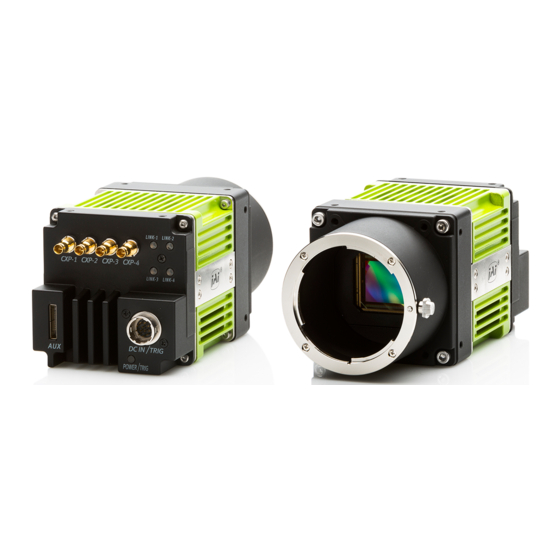
Page 11: Locations And Functions
SP-5000M-CXP4 / SP-5000C-CXP4 Locations and functions Locations and functions Lens mount C-mount (Note *1) 10-pin connector AUX Connector for lens control (Standard) LED Indication for power and trigger input 12-pin connector DC and trigger input LINK LEDs LINK 1 through 4 Status indication for CoaXPress interface ... -
Page 12: Rear Panel
SP-5000M-CXP4 / SP-5000C-CXP4 Rear panel The rear panel mounted LEDs provide the following information: POWER/TRIG Amber: Power connected – initiating This light goes OFF after initiating. Steady green: Camera is operating in Continuous mode Flashing green: The camera is receiving external triggering ... -
Page 13: Input And Output
CXP-6 6.250 (up to 68 m) In the SP-5000M-CXP4 and SP-5000C-CXP4, the maximum bit rate is 6.25 Gbps per one cable and the power supply is available on the CXP#1 connector only. For the details of the specifications, please refer to “JIIA-NTF-001-2010” published by Japan Industrial Imaging Association, http://www.jiia.org. - Page 14 SP-5000M-CXP4 / SP-5000C-CXP4 CoaXPress Interface Number of Lanes 1, 2, and 4 PoCXP is applied to Only Link1. PoCXP Link2, Link3 and Link4 are not available CXP Output Maximum frame rate 8 Bit 53 fps MONO 10 Bit 42 fps...
-
Page 15: Connectors And Pin Assignment
SP-5000M-CXP4 / SP-5000C-CXP4 Connectors and pin assignment 5.2.1 Digital Video Output (75Ω 1.0・2.3 DIN Receptacle) Type: CoaXPress Connector (ACX1785-ND Amphenol Connector or equivalent) The SP-5000-CXP4 has three connecting systems described in 5.1.2. They are one lane, two lanes and four lanes connecting systems. -
Page 16: Aux Standard Hirose 10-Pin Connector
SP-5000M-CXP4 / SP-5000C-CXP4 5.2.3 AUX Standard Hirose 10-Pin connector 5.2.3.1 Figure and pin configuration Type : HIROSE 10-Pin Connector 3260-10S3(55) Fig.5 Hirose 10-pin connector Table – 5 Hirose 10P pin assignment (Standard) Name Note DRIVE IRIS+ Motorized Lens DRIVE FOCUS+... -
Page 17: Aux Type 3 Hirose 10-Pin Connector (Factory Option)
LVDS_IN1+ Line11 LVDS_IN1- Digital IN/OUT interface In the SP-5000M-CXP4 and SP-5000C-CXP4, the digital IN/OUT capability in the software control tool can assign the necessary signals needed for the system. 5.3.1 Line Selector In the Line Selector, the following input and output signals can be assigned. -
Page 18: Line Mode
SP-5000M-CXP4 / SP-5000C-CXP4 Table - 9 Line Source Line Source item Description Connect Low Level signal to line item selected in Line Selector, Default setting High Connect High Level signal to line item selected in Line Selector Acquisition Trigger Wait... -
Page 19: Basic Block Diagram
SP-5000M-CXP4 / SP-5000C-CXP4 5.3.7.1 Basic block diagram Sel Bit (5,0) Sel Bit (7) Soft Trigger Trigger 0 (Acquisition Start) Trigger 1 (Acquisition Stop) FVAL IN Trigger 2 (Frame Start) Exposure Active GPIO 1 (TTL OUT 1) Acquisition Trigger Wait Sel Bit (7) -
Page 20: In And Out Matrix Table
SP-5000M-CXP4 / SP-5000C-CXP4 5.3.7.2 IN and OUT matrix table The following table shows the input and output matrix table. Table – 10 GPIO IN and OUT matrix table Selector (Cross Trigger Pulse Generator Line Selector point switch output) Selector Selector... -
Page 21: Associated Genicam Registers
SP-5000M-CXP4 / SP-5000C-CXP4 5.3.8 Associated GenICam registers GenICam Access Values Category Name Line1 to 11 Nand Gate 0 In1 Line Nand Gate 0 In2 Digital I/O Control Selector Nand Gate 1 In1 Nand Gate 1 In2 Line Output Digital I/O Control... -
Page 22: Clock Pre-Scaler
SP-5000M-CXP4 / SP-5000C-CXP4 Table - 11 Pulse Generator default settings Display Name Value Clock Pre-scaler Pulse Generator Length Start Repeat Clear Clear Clear Clear Pulse Generator Point Point Count Source Inverter Activation Sync Selector Mode True Async Mode Pulse Generator 0... -
Page 23: Pulse Generator Length
SP-5000M-CXP4 / SP-5000C-CXP4 5.4.3 Pulse Generator Length Set the counter up value (number of clocks, refer to Table 14) for the selected pulse generator. If Repeat Count value is “0”, and if Pulse Generator Clear signal is not input, the pulse generator generates the pulse repeatedly until reaching this counter up value. -
Page 24: Pulse Generator Clear Source
SP-5000M-CXP4 / SP-5000C-CXP4 (Example 2) Clear Activation = Rising Edge, Clear Sync Mode = Sync Mode, Clear Inverter = False Pulse Generator Clear Source In Pulse Generator Output Clear ↓ Pulse Note: Repeat Count is also reset. Generator Length Fig.9 Counter clear in Sync mode 5.4.9... -
Page 25: Pulse Generator Setting Parameters
SP-5000M-CXP4 / SP-5000C-CXP4 5.4.11 Pulse Generator Setting Parameters Table - 14 Pulse Generator setting parameters Display Name Value Clock Pre-scaler 1 to 4096 Pulse Generator Clock (MHz) [Pixel Clock: 86.4 MHz]÷[Clock Pre-scaler] Pulse Generator Selector - Pulse Generator 0 - Pulse Generator 1... -
Page 26: Associated Genicam Registers
SP-5000M-CXP4 / SP-5000C-CXP4 5.4.12 Associated GenICam registers GenICam Name Access Values Category Pre-scaler 1 to 4096 Pulse Generators Pulse Generator Selector PG0 to PG3 Pulse Generators Pulse Generator Length 0 to 1048575 Pulse Generators Pulse Generator Start 0 to 1048575... -
Page 27: Sensor Layout, Output Format And Timing
SP-5000M-CXP4 / SP-5000C-CXP4 Sensor layout, output format and timing Sensor layout CMOS sensors used in the SP-5000M-CXP4 and SP-5000C-CXP4 have the following tap and pixel layout. 6.1.1 Monochrome sensor 2560 Pixels Pixel (0,0) Fig.10 Monochrome sensor layout 6.1.2 Bayer color sensor... -
Page 28: Camera Output Format
SP-5000M-CXP4 / SP-5000C-CXP4 6.2. Camera output format The following table shows the relationship between camera output and sensor readout system. Camera output format Sensor readout system Reference figure 1X–1Y 1-tap readout 6.2.1 Note: The description of camera output format is based on GenICam SFNC Ver.1.5.1. -
Page 29: Output Timing
SP-5000M-CXP4 / SP-5000C-CXP4 Output timing 6.3.1 Horizontal timing Sensor Pixel Format: 8-bit Output format: 1X–1Y 1 Clock: 11.574 ns FVAL Video Data Fig.13 Horizontal timing (Timing inside the camera) FVAL rising position FVAL falling position Video Data 160 clocks Video Row Cycle 165 clocks 1 ~4 clk... -
Page 30: Vertical Timing
SP-5000M-CXP4 / SP-5000C-CXP4 6.3.2 Vertical timing Sensor Pixel Format: 8-bit Output format: 1X–1Y, CXP-6_2 Trigger Mode: ON, Exposure Mode: Timed 1L: 165 clocks, 1 clock: 11.574 ns 6.3.2.1 Vertical Binning OFF FVAL 2048L 12 ~13L(Min) DVAL CMOS Exposure 8 ~9L... -
Page 31: Roi (Region Of Interest) Setting
SP-5000M-CXP4 / SP-5000C-CXP4 6.3.3 ROI (Region Of Interest) setting In the SP-5000-CXP4, a subset of the image can be output by setting Width, Height, Offset-X, and Offset- Y. If the height is decreased, the number of lines read out is decreased and as the result, the frame rate is increased. -
Page 32: Operating Modes
Allowed values range from 25691 Hz to 0.125 Hz for SP-5000M-CXP4, however if the frequency entered is faster than the time required for the default frame rate, the setting is ignored and the default frame rate is used. For example, the minimum frame period for the smallest possible ROI (64H x 8V) requires 25691 Hz, so any entry more than 25691 will always be ignored. -
Page 33: Exposure Setting
SP-5000M-CXP4 / SP-5000C-CXP4 2. If Sensor Pixel Format is RGB24bit × ( ���������� + �� + 2 ) + 1 + ( �� × 3 ) + ������������_�� �� ������ ������ �� �� 2 �������������� [ ������ ] ��_ ������... -
Page 34: Exposure Mode
SP-5000M-CXP4 / SP-5000C-CXP4 7.2.1 Exposure Mode The exposure mode can be selected from the following three ways. Table35. Exposure mode Exposure Mode setting Exposure operation No exposure control (free-running operation) Exposure operation at the value set in Exposure Time. Setting value is usec unit. -
Page 35: Exposure Time
Acquisition Control 8000000 [us] 7.2.3 Exposure Auto This is a function to control the exposure automatically. It is effective only for Timed. JAI ALC Reference controls the brightness. There are three modes, OFF, Once and Continuous. OFF: No exposure control Once:... -
Page 36: Trigger Control
SP-5000M-CXP4 / SP-5000C-CXP4 Associated GenICam registers GenICam Access Values Category Name Exposure Continuous Acquisition Control Auto Once Exposure JAI-Custom Auto Max 8000000 Exposure JAI-Custom Auto Min 8000000 7.3. Trigger Control 7.3.1 Trigger Source The following signals can be used as the trigger source signal. -
Page 37: Normal Continuous Operation (Timed Exposure Mode/Trigger Mode Off)
SP-5000M-CXP4 / SP-5000C-CXP4 7.3.4 Associated GenICam registers GenICam Access Values Category Name Acquisition Start Trigger Acquisition End Acquisition Control Selector Frame Start Trigger Acquisition Control Mode Trigger Command Acquisition Control Software High Software Trigger Frame Trigger Wait Frame Active Exposure Active... -
Page 38: Timed Mode
SP-5000M-CXP4 / SP-5000C-CXP4 7.5. Timed mode This mode allows a single image frame to be captured with a preset exposure time by using the external trigger. Additional settings determine if the trigger pulse can be accepted during the exposure period. -
Page 39: Trigger Width Mode
SP-5000M-CXP4 / SP-5000C-CXP4 7.6. Trigger width mode In this mode, the exposure time is equal to the trigger pulse width. Accordingly, longer exposure times are supported. Additional settings determine if the trigger pulse can be accepted during the exposure period. -
Page 40: Rct Mode
SP-5000M-CXP4 / SP-5000C-CXP4 7.7. RCT mode Until the trigger is input, the camera operates continuously and the video signal for the auto-iris lens is output provided the AUX connector has been ordered with a Type 2 configuration option. At this moment, the video signal, FVAL and LVAL are output but DVAL is not output. When the trigger is input, the fast dump is activated to read out the electronic charge very quickly, after which the accumulation and the readout are performed. -
Page 41: Piv (Particle Image Velocimetry)
SP-5000M-CXP4 / SP-5000C-CXP4 7.8. PIV (Particle Image Velocimetry) The Particle Image Velocimetry mode can be used in applications where 2 images need to be taken with a very short time interval. It can only be used with strobe flash as illumination. -
Page 42: Sequence Mode
SP-5000M-CXP4 / SP-5000C-CXP4 30.6 us 44.4 us 44.4 us 78.6 us 78.6 us 154 us 73.4 us 73.5 us 73.5 us 73.4 us 73.4 us 73.4 us 8bit 4L~5L 3L~4L 3L~4L 3L~4L 3L~4L 2L~3L 2085L 2073L 2079L 2071L 2071L 2063L Fig.23... -
Page 43: Sequence Mode Basic Timing
SP-5000M-CXP4 / SP-5000C-CXP4 7.9.2 Sequence mode basic timing In this mode, as each trigger input is received, the image data associated with the next index within the preset sequence is output. Frame Start Trigger In Sequence Index 0 Index 1... - Page 44 In Sequence ROI Gain Selector, the gain settings for each index are available. SP-5000C-CXP4: Gain (ALL), Red and Blue can be set. SP-5000M-CXP4: Only Gain is displayed and can be set. (7) Sequence ROI Black Level Black Level setting is available for each index.
-
Page 45: Associated Genicam Registers
Sequence ROI LUT Enable JAI-Custom Sequence Black -256 to 255 JAI-Custom Level Sequence ROI Gain Red -45 to 379 JAI-Custom (for Color Model) Sequence ROI Gain Blue -45 to 379 JAI-Custom (for Color Model) Note: binning is only for SP-5000M-CXP4. - 43 -... -
Page 46: Multi Roi Function
SP-5000M-CXP4 / SP-5000C-CXP4 7.10 Multi ROI function This function divides one frame image into a maximum of 8 images vertically and reads out all areas in one frame. In this function, width is the same for all 8 images. The multi ROI function is enabled if [Video Sending Mode] is set to “Multi ROI”. - Page 47 SP-5000M-CXP4 / SP-5000C-CXP4 ROI setting explanation if Multi ROI Index is set to 1, 2, 3 and 4 Index 4 Offset X Index 2 Offset X Index 1 Offset X Index 3 Offset X Index 1 Offset Y Index 1 Height...
-
Page 48: Associated Genicam Registers
○ × Timed (PIV) × 2 2 ○ × × × × × × × Note 1. Only SP-5000M-CXP4 Note 2: Only SP-5000C-CXP4 Note 3: If the trigger interval is long, iris may exhibit a hunting phenomenon. - 46 -... -
Page 49: Other Functions
SP-5000M-CXP4 / SP-5000C-CXP4 Other functions Black level control This function adjusts the setup level. The adjusting level is -256 to +255LSB at 10-bit output. 8.1.1 Black Level Selector The following factors can be set. SP-5000M-CXP4: DigitalAll SP-5000C-CXP4: DigitalAll/DigitalRed/ DigitalBlue 8.1.2 Black Level The black level can be set in the following range. -
Page 50: Gain Selector
SP-5000C-CXP4: DigitalAll:100~1600 Digital Red All/Digital Blue All:-45~379 8.2.4 Gain Auto This function automatically controls the gain level. This is controlled by the command JAI ALC Reference. There are three modes. OFF: Adjust manually. Once: Operate only one time when this command is set... -
Page 51: Associated Genicam Registers For Gain Control
SP-5000M-CXP4 / SP-5000C-CXP4 The following detailed settings are also available. ALC Speed: The rate of adjustment of GainAuto can be set (Common with ExposureAuto). Gain Auto Max: The maximum value of GainAuto control range can be set Gain Auto Min:... -
Page 52: Balance White Auto
SP-5000M-CXP4 / SP-5000C-CXP4 ALC Channel Area Middle High Middle JAI-Custom Right ALC Channel Area JAI-Custom Middle High Middle Left ALC Channel Area JAI-Custom Middle High Left ALC Channel Area JAI-Custom High Right ALC Channel Area JAI-Custom High Middle Right ALC Channel Area... -
Page 53: Lut
SP-5000M-CXP4 / SP-5000C-CXP4 Balance White Channel Area JAI-Custom Middle Low Left Balance White Channel Area JAI-Custom Middle High Right Balance White Channel Area JAI-Custom Middle High Middle Right Balance White Channel Area JAI-Custom Middle High Middle Left Balance White Channel Area... -
Page 54: Lut Value
SP-5000M-CXP4 / SP-5000C-CXP4 8.3.3 LUT value This is the “adjusted” or “output” pixel value for a given LUT index. It has a range of 0 to 4095 (12- bit) and is automatically scaled to the bit depth of the current operating mode (8-bit or 10-bit). -
Page 55: Linear Or Dark Compression
SP-5000M-CXP4 / SP-5000C-CXP4 8.4.1 Linear or Dark Compression SP-5000-CXP4 has a function which improves the signal to noise ratio in the dark portion of the video. The default setting is Linear but users can select Dark Compression if it is appropriate for their application. -
Page 56: Blemish Compensation
8.6. Blemish compensation The SP-5000M-CXP4 and SP-5000C-CXP4 have a blemish compensation circuit. This function compensates blemishes on the CMOS sensor (typically pixels with extremely high response or extremely low response). This applies to both monochrome and color versions. Pixels that fulfill the... -
Page 57: Bayer Color Interpolation (Only For Sp-5000C-Cxp4)
Fig.36 Color interpolation concept drawing Lens control The SP-5000M-CXP4 and SP-5000C-CXP4 can be used with 4 different types of auto iris lenses, in addition to standard lenses with manual iris control. If an auto iris function is to be utilized, the lens type used must be selected in Lens Select. -
Page 58: About P-Iris
8.8.1 About P-Iris New Spark Series SP-5000M-CXP4 and SP-5000C-CXP4 come equipped with P-Iris control as part of the standard lens control function. The P-Iris system is a newly developed lens control method designed to control the iris more precisely. Especially for video cameras in surveillance applications utilizing megapixel CCD or CMOS imagers, it becomes a very important factor to control an iris in order to achieve the maximum camera performance. -
Page 59: P-Iris Auto Min. / P-Iris Auto Max
SP-5000M-CXP4 / SP-5000C-CXP4 1) When the camera is powered 2) When the lens is selected in P-Iris Lens Select 3) If the lens is changed in P-Iris Lens Select 8.8.2.4 P-Iris Auto min. / P-Iris Auto max. This function can set the control range when the iris is operated automatically. Auto max. sets the limit when the iris goes open and Auto min. -
Page 60: Alc
Near JAI-Custom In the SP-5000M-CXP4 and SP-5000C-CXP4, auto gain, auto shutter and auto iris functions can be combined to provide a wide ranging automatic exposure control from dark to bright or vice versa. The functions are applied in the sequence shown below and if one function is disabled, the linkage between the other two is maintained. - Page 61 SP-5000M-CXP4 / SP-5000C-CXP4 Dark Light changes Bright AGC operation Gain is fixed at Min. AGC works: Max ~ Min (User set) Auto Shutter Auto shutter operation Auto Shutter Auto shutter works: Max ~ Min (User set) fixed at Min Auto iris works:...
-
Page 62: Hdr (High Dynamic Range) (Sp-5000M-Cxp4 Only)
High Left 8.10 HDR (High Dynamic Range) (SP-5000M-CXP4 only) HDR sensing mode can be set when HDR Mode is set to ON while Exposure Mode is Timed. The parameters to configure dynamic range are HDR_SLOPE Level 1, Level 2, Level 3 and Level 4. - Page 63 SP-5000M-CXP4 / SP-5000C-CXP4 Level 1 Level 2 Level 3 Level 4 Input Fig. 38 HDR characteristics Knee Slope Dynamic Range [%] (200) (400) (800) (1600) Associated GenICam register GenICam Access Values Category Name Disable JAI-Custom Enable Enable HDR Slope 200%...
-
Page 64: Camera Setting
Camera setting Camera Control Tool In the SP-5000M-CXP4 and SP-5000C-CXP4, control of all camera functions is done by the JAI SDK and Control Tool software. All controllable camera functions are stored in an XML file inside of the camera. The JAI SDK and Control Tool software can be downloaded from www.jai.com. -
Page 65: External Appearance And Dimensions
SP-5000M-CXP4 / SP-5000C-CXP4 External appearance and dimensions Dimensions tolerance: ± 0.3mm Unit: mm Fig. 39 Outside dimensions - 63 -... -
Page 66: Specifications
SP-5000M-CXP4 / SP-5000C-CXP4 Specifications 11.1 Spectral response Fig. 40 Spectral response (SP-5000M-CXP4) Fig.41 Spectral response (SP-5000C-CXP4) (With IR Cut Filter) - 64 -... -
Page 67: Specifications Table
SP-5000M-CXP4 / SP-5000C-CXP4 11.2 Specifications table Specifications SP-5000M-CXP4 SP-5000C-CXP4 Scanning system Progressive scan, 1-tap Synchronization Internal CoaXPress (JIIA NIF-001-2010 CoaXPress Standard First Edition) Interface 6.25 Gbps, 4 links, Compliant with PoCXP Image sensor 1 inch Monochrome CMOS 1 inch Bayer color CMOS... - Page 68 SP-5000M-CXP4 / SP-5000C-CXP4 Trigger Width 10 μs (Min.) ~ ∞ (Max.) Auto Exposure OFF / Once / Continuous Auto Exposure Response Speed 1 ~ 8 Line Selector (12P): GPIO IN / GPIO OUT Line4 TTL in: High Level: 2V to 5V, Low level: Less 1V, Input Resistance:1.5KΩ...
- Page 69 SP-5000M-CXP4 / SP-5000C-CXP4 Weight 215g Note1): Continuity of the Histogram is guaranteed for up to 12dB of gain. Note2): Approximately 5 minutes pre-heating is required to achieve these specifications. Note3): The above specifications are subject to change without notice. - 67 -...
-
Page 70: Appendix
SP-5000M-CXP4 / SP-5000C-CXP4 Appendix 1. Precautions Personnel not trained in dealing with similar electronic devices should not service this camera. The camera contains components sensitive to electrostatic discharge. The handling of these devices should follow the requirements of electrostatic sensitive components. -
Page 71: Exportation
5. Exportation When exporting this product, please follow the export regulation of your own country. 6. References 1. This manual and datasheet for SP-5000M-CXP4 / SP-5000C-CXP4 can be downloaded from www.jai.com 2. Camera control software can be downloaded from www.jai.com... -
Page 72: Manual Change History
SP-5000M-CXP4 / SP-5000C-CXP4 Manual change history Date Revision Changes Oct. 2014 Preliminary First issue Jan. 2015 Ver.1.0 Release - 70 -... -
Page 73: User's Record
Company and product names mentioned in this manual are trademarks or registered trademarks of their respective owners. JAI A-S cannot be held responsible for any technical or typographical errors and reserves the right to make changes to products and documentation without prior notification.
Need help?
Do you have a question about the SP-5000M-CXP4 and is the answer not in the manual?
Questions and answers