
Subscribe to Our Youtube Channel
Related Manuals for JAI LT-400CL


Summary of Contents for JAI LT-400CL
- Page 1 User's Manual LT-400CL 3CMOS High Speed Color Line Scan Camera Document Version: Ver.1.3 LT-400CL_Ver.1.3_Nov2011 1011E-0909...
- Page 2 JAI Ltd., Japan and may only be used by the purchasers of the product. JAI Ltd., Japan makes no warranty for the use of its product and assumes no responsibility for any errors which may appear or for damages resulting from the use of the information contained herein.
- Page 3 LT-400CL Supplement The following statement is related to the regulation on “ Measures for the Administration of the control of Pollution by Electronic Information Products “ , known as “ China RoHS “. The table shows contained Hazardous Substances in this camera.
-
Page 4: Table Of Contents
Compatibility of trigger modes and functions ..........33 Configuring the camera ................... 34 7.1. RS-232C control ..................34 7.2. LT-400CL Command list ................35 Functions listed alphabetically by command acronyms ..........40 8.1. Command AH – One-push AWB shutter ............40 8.2. - Page 5 8.40 Command TS – Test pattern ................ 49 8.41 Command WB – White Balance ..............49 Camera Control Tool for LT-400CL ..............50 10. External appearance and Dimensions ..............53 11 . Specifications .................... 55 11.1 Typical data .................... 55 11.2 Spectral sensitivity ..................
-
Page 6: General
LT-400CL 1. General LT-400CL is a 3CMOS line scan camera using three 4096 pixel line sensors mounted on a prism, for the R, G and B channels. It operates with an 80 MHz pixel clock, resulting in a maximum line rate of 16,180 lines per second. -
Page 7: Locations And Functions
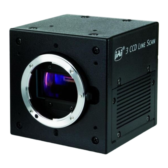
LT-400CL Locations and functions 4.1. Main unit ① ④ ③ ⑨ POWER/ TR IG ⑤ W.B. DC IN / TR IG ⑨ ⑧ ⑦ ② ⑥ Fig. 1 Location of external features Camera Link base connector (1) (*Note1) Camera Link medium connector (2) (*Note1) -
Page 8: Rear Panel And Indicators
LT-400CL 4.2. Rear Panel and indicators Rear panel indicator LED Push button DIP switch Fig.2 Rear panel LED There is a multi-color LED on the rear panel of the camera. It has the following functions: Green (Steady) Operating, but not receiving external trigger input Green (Flashing) -
Page 9: Input And Output (Connectors, Signals And Circuits)
Cables, transmission systems and frame grabbers/acquisition boards that do not comply with the Camera Link standard may work with this camera, but JAI Camera Solutions cannot be held responsible for loss in performance or damage of equipment, including the camera. -
Page 10: Camera Link Output
11,24 12,25 13,26 Shield The LT-400CL follows the Camera Link standard in all respects. Please refer to the Camera Link version 1.1 specifications for detailed information on bit assignments of 24-bit RGB and 30-bit bit output. 5.3. Camera Link output RD9~RD0 : R Channel Camera Data(RD9=MSB, RD0=LSB) - Page 11 LT-400CL Port/Signal 24bit Output 30bit Output Connector Pin Name Port A0 Port A1 Port A2 Port A3 Port A4 Port A5 Port A6 Tx27 Port A7 Port B0 Port B1 Port B2 × Port B3 Tx12 × Port B4 Tx13...
-
Page 12: Input And Output Circuits
LT-400CL 5.4. Input and output circuits 5.4.1 Trigger input The External Trigger signal can be applied either through the Camera Link connector or at pin 10 of the 12-pin Hirose connector. The command to change this setting is TI (Trigger Input). -
Page 13: Functions And Operation
6.2. Sensor layout and output timing The LT-400CL uses newly developed COMS sensors which have 4096 effective pixels. Light received on photodiodes is converted to electronic signals and these signals are handled in a correlated double sampling circuit, analog gain circuit and analog digital converter circuit. -
Page 14: Key Functions
LT-400CL Fig.9 Sensor layout Fig.10 Video output timing 6.3. Key functions 6.3.1 Line rate (Command LR) This function can set the line rate longer than 1L. Accordingly, it is possible to set the camera scan rate with the object running speed or to boost up the sensitivity by setting longer exposure time. -
Page 15: Een (Exposure Enable) Function
LT-400CL Line rate > Exposure time Line rate (LR) = 20000 Tri gger ( I nternal /External ) Exposure (Rch) =22000 Exposure R Exposure G Exposure B In this case, although the expsore time is set at 22000, but the actual exposure time is limited by the line rate, 20000. -
Page 16: Gain Control
6.3.5 Gain control The LT-400CL has two ways of gain setting - one for the master tracking and the other for individual adjustment. Each setting also has two analog gain modes - one is the GAIN LOW and the other is the GAIN HIGH. When the Gain Low is selected, gain for each channel can be adjusted from -4dB to +14dB as the reference of 0dB which is the default output setting. -
Page 17: Setup Level
LT-400CL 2. Individual gain mode Gain Low mode: Reference value: 0dB R/G/B Adjusting range :-4dB to +14dB (at the master gain setting value) Gain High mode: Reference value: +6dB R/G/B Adjusting range :-4dB to +14dB (at the master gain setting value) ... -
Page 18: Knee Correction
LT-400CL 6.3.7 Knee correction If the relationship of input and output is linear (1:1), the output level will be clipped at a certain input level and cannot reproduce the details in the clipped area. The knee compensation circuit can keep the linear relationship until the knee point, while after the knee point, the output signal is compressed to reproduce the details. -
Page 19: Dsnu (Dark Signal Non-Uniformity) Correction
LT-400CL To correct for PRNU, the camera’s internal correction circuit captures one or several lines of data under non-saturated illuminated conditions which are not more than 80% of maximum (recommend level is half of maximum), and the average across the line is calculated. -
Page 20: Shading Correction
LT-400CL 6.3.10 Shading correction Shading is caused either by illumination with uneven distribution of light across the surface, or by reductions in the light transmission ratio towards the edges of a lens. The shading correction incorporated in the camera will compensate for this effect by as much as 20% of the brightest signal. -
Page 21: Binning
2 0 4 7 2 0 4 8 Fig.23 Windowing reads out only 2048 pixels at the center 6.3.14 Test pattern generator LT-400CL has four test pattern generators. In the following drawings, figures in shown in ( ) are for 8 bits output. -
Page 22: Color Bar
LT-400CL Color bar Fig.24 color bar test pattern Gray 1 890( 222) Si gnal (RGB) 32( 8) DVAL 0 4095 Fig.25 Gradation test pattern Gray 2 890( 222) Si gnal (RGB 32( 8) 16 16 16 16 16 16 16 16 16 16 16 16 ・・・... -
Page 23: Operation Modes
LT-400CL 6.4. Operation modes The LT-400CL has the following operation modes. Trigger Mode Trigger origin Command Description Command Description TR=0 No-shutter TG=0 Internal TG=1 External TR=1 Shutter select TG=0 Internal TG=1 External TR=2 Pulse width control TG=1 6.4.1 No-shutter mode with internal trigger In this mode the camera does not accept an external trigger signal, as the line rate is generated from an internal clock (user programmable, command LR). - Page 24 LT-400CL 1496clk 896clk LVAL 16clk 4096clk 16clk DVAL AP409 Data Fig.30 No-shutter / internal trigger mode 1496clk 896clk LVAL 16clk 4096clk 16clk DVAL AP409 Data Fig.31 No-shutter mode / Binning/ Internal...
-
Page 25: No-Shutter Mode With External Trigger
LT-400CL 1496clk 896clk LVAL 16clk 2048clk 16clk DVAL AP204 Data Fig.32 No-shutter /Sub-sampling and Window/ Internal 6.4.2 No-shutter mode with external trigger In this mode, the exposure time is directly proportional to the line rate. The line rate is generated externally by a trigger signal. This mode is used when an external trigger signal is available, e.g. - Page 26 LT-400CL 147clk 1496clk 1043clk LVAL 16clk 4096clk 16clk DVAL AP409 Data Fig. 33 No-shutter mode with external trigger 147clk 1496clk 1043clk LVAL 16clk 4096clk 16clk DVAL AP409 Data Fig. 34 No-shutter mode /Binning/ External...
-
Page 27: Shutter-Select Mode With Internal Trigger
LT-400CL 147clk 1496clk 1043clk LVAL 16clk 2048clk 16clk DVAL AP204 Data Fig.35 No-shutter mode /Sub-sampling and Window/ External 6.4.3 Shutter-select mode with internal trigger This mode allows the user to have full control of the line rate and the exposure time individually, by programming separate timing generators. - Page 28 LT-400CL Note 1 Exposure R Exposure G Exposure B 896clk 896clk LVAL 16clk 4096clk 16clk DVAL AP409 Data Note: EEN is used a channel with the largest exposure value Fig. 36 Shutter-select mode with internal line rate generator (and individual exposure)
-
Page 29: Shutter-Select Mode With External Trigger
LT-400CL Note 1 Exposure R Exposure G Exposure B 896clk 896clk LVAL 16clk 2048clk 16clk DVAL AP204 Data Note: EEN is used a channel with the largest exposure value Fig.38 Shutter –select mode/Sub-sampling and Window/ Internal 6.4.4 Shutter-select mode with external trigger This mode allows the user to have full control of the exposure time, by programming a timing generator, while the line rate is controlled by an external trigger signal. - Page 30 LT-400CL The minimum trigger pulse width Trigger input via Minimum trigger pulse width Camera link 500 ns Hirose 12-pin 5µs The maximum exposure time is the line rate. When the one-push white balance has been initiated and the rear panel LED shows orange, the camera must receive continuous external trigger pulses corresponding to the frequency and duty cycle used in the application.
- Page 31 LT-400CL 851clk Note 1 Exposure R Exposure G Exposure B 896clk LVAL 16clk 4096clk 16clk DVAL AP409 Data Note: EEN is used a channel with the largest exposure value Fig.40 Shutter select mode /Binning /External 851clk Note 1 Exposure R...
-
Page 32: Pulse Width Control (Pwc) Mode
LT-400CL 6.4.5 Pulse Width Control (PWC) mode In this mode, the user has full control of both the line rate and the exposure time of each line via the External Trigger input. At the rising edge of the External Trigger signal, the exposure is initiated, and at the falling edge the exposure is terminated and read out. - Page 33 LT-400CL 851clk 128clk 896clk LVAL 16clk 4096clk 16clk DVAL AP409 Data Fig.43 PWC mode /Binning 851clk 128clk 896clk LVAL 16clk 2048clk 16clk DVAL AP204 Data Fig.44 PWC mode /Sub-sampling and Window...
-
Page 34: Compatibility Of Trigger Modes And Functions
LT-400CL 6.4.6 Compatibility of trigger modes and functions Trigger Image output format Gain Offset Full Master Mode Origin Binning Windowing Gain Low Gain High Individual resolution sampling tracking Internal No-Shutter ◎ ◎ ◎ ◎ ◎ ◎ ◎ ◎ External Internal Shutter ◎... -
Page 35: Configuring The Camera
7.1. RS-232C control All configuration of the LT-400CL camera is done via the RS-232C port on the 12-pin HR connector or via Camera Link. The camera can be set up from a PC running terminal emulator software, or using JAI's camera control software. -
Page 36: Lt-400Cl Command List
The camera answers: 02 Bad Parameters!!<CR><LF> To see firmware number. VN?<CR><LF> To see camera ID. It shows the manufacturing lot number. ID?<CR><LF> 7.2. LT-400CL Command list Command Name Format Parameter Remarks A – General settings and useful commands. EB=[Param.]<CR><LF> 1 Echo Back... - Page 37 LT-400CL C - Line Rate, Exposure Full resolution 4944 to 1201920 clocks LR=[Param.]<CR><LF> 1 Line Rate Sub-sampling/window Available when TG=0 LR?<CR><LF> 2921 to 597376 clocks - 1 clock is 12.5ns One-push auto line 0=Activate one-push auto AR=[Param.]<CR><LF> Available when TG=0...
- Page 38 LT-400CL E - Gain, white balance and signal settings Gain Level GA=[Param.]<CR><LF> 0 to 800 (GM=0) 100=1dB -400 to 1400 (GM=1) Master GA?<CR><LF> GAR=[Param.]<CR><LF> -400 to 600 (GM=0) 2 Gain Level - Red GAR?<CR><LF> -400 to 1400 (GM=1) GAB=[Param.]<CR><LF> -400 to 600...
- Page 39 LT-400CL KSR?<CR><LF> Knee Slope – KSG=[Param.]<CR><LF> 0 to 65535 Green KSG?<CR><LF> KSB=[Param.]<CR><LF> 19 Knee Slope – Blue 0 to 65535 KSB?<CR><LF> KPR=[Param.]<CR><LF> 20 Knee Point – Red 0 to 1023 KPR?<CR><LF> Knee Point – KPG=[Param.]<CR><LF> 0 to 1023 Green KPG?<CR><LF>...
- Page 40 LT-400CL 0=Off (Bypass) Select pixel black PBC=[Param.]<CR><LF> 1=Factory area correction mode PBC?<CR><LF> 2=User area Run pixel black 0=Run pixel black correction, correction, store PBR=[Param.]<CR><LF> Store in user setting. store to user area to user area 0=Pixel black correction has not been funished yet.
-
Page 41: Functions Listed Alphabetically By Command Acronyms
LT-400CL Functions listed alphabetically by command acronyms 8.1. Command AH – One-push AWB shutter This command controls a white balance by setting an appropriate shutter speed each channel. Settings: 0 to initiate Applicable modes: TR=1 Shutter select mode Associated functions:... -
Page 42: Command Arst - Auto Reset Mode
LT-400CL Command ARST – Auto reset mode In the no-shutter and external trigger mode, if the trigger is input after a long time interruption, more than 52msec , the over exposed signal during the trigger interruption is output after the first trigger. In this case, if ARST mode is ON, LAVL, DVAL and video signal are not output during the trigger interruption and LAVL, DVAL and video signal are output after the second trigger input. -
Page 43: Command Bi - Binning (Horizontal Only)
LT-400CL Settings: 0=24-bit, 1=30-bit Applicable modes: Command BI – Binning (Horizontal only) This function reduces the number of pixels to 256 without affecting the line rate. Two adjacent pixels are combined at the output stage and read out as one pixel. Sensitivity is doubled as a result of binning. -
Page 44: Command Ga - Gain Level Master / G Channel
LT-400CL Applicable modes: TR=1 Shutter-select mode only Associated functions: Commands PER, PEG, PEB – Programmable Exposure Refer to 6.3.2 Electronic shutter (Exposure)(Command PER,PEG,PEB) for further details. 8.14 Command GA – Gain level master / G channel Adjust the master gain or G channel gain in accordance with gain mode (GM). -
Page 45: Command Lr - Line Rate (Scan Rate)
LT-400CL 8.20 Command LR - Line Rate (Scan Rate) This function is used only when there is no external trigger pulse (e.g. from an encoder) available. It allows the user to program the line rate, in order to match the speed of the object being scanned. -
Page 46: Command Pbs - Inquire The Status Of After Pixel Black Correction
LT-400CL 8.24 Command PBS – Inquire the status of after pixel black correction This command returns the status of the pixel black correction, with the following parameters: 0=Shading correction not completed yet 1=Successful 2=Error 1 – Image was too bright 3=Error 2 –... -
Page 47: Command Pgr - Run Pixel Gain Correction And Store In User Area
LT-400CL 8.29 Command PGR – Run pixel gain correction and store in user area This command initiates the flat-field correction function, and stores the settings in the user area. Settings: 0= Run PRNU correction and store to user area 1= Run flat correction and store to user area... - Page 48 LT-400CL Individual shading correction per channel Important note: Depending on the optics and/or illumination used together with the camera, it may not be possible to fully compensate for shading. Operating procedure for individual R, G and B channel shadings correction: 1.
-
Page 49: Command Sds - Request Status After Executing Shading Correction Command
LT-400CL 4. Set command SDR to 1 to initiate shading correction. 5. If desired, set command PGR to 0 to activate flat-field (pixel gain) correction to correct for pixel response non-uniformity. 6. Again set SDR=1 after running the flat-field (pixel gain) correction Refer to chapter 6.3.10 Shading correction... -
Page 50: Command Tp - Trigger Polarity
LT-400CL 8.38 Command TP – Trigger polarity Settings: 0=Active Low (factory default) 1=Active High 8.39 Command TR – Trigger Mode Selects the trigger mode of the camera. Depending on the mode used, it allows the scan rate to either be programmed by an internal timing generator or by an external trigger pulse. -
Page 51: Camera Control Tool For Lt-400Cl
Connect the camera to the PC on which the software is installed and set the power ON. Then select “All programs” in the Windows start menu, select “JAI A-S” and click “LT-400CL control tool”. LT-400CL Camera Control Tool and Communication windows will open. - Page 52 LT-400CL 9.4. Camera control window When the connection between camera and PC is completed, the camera control tool shows the current camera settings. 9.5. Menu 9.5.1 File menu Open: Transfer the setting parameters in HDD or other memory devices to the camera.
- Page 53 LT-400CL 9.5.3 Line Correction menu Click Line Correction menu and a drop-down menu will open. The setting window for shading, pixel gain and pixel black can be opened. 9.5.4 Help menu Display camera software version, model name, firmware version and camera ID.
-
Page 54: External Appearance And Dimensions
LT-400CL 10. External appearance and Dimensions 4-M3 depth5 (depth0.20) 25.5 +0.012 (0.28) (1.00) φ4 depth3.5 (depth0.14) 32.5 (2.36) (1.28) (3.54) 4-M3 depth3.5 (0.28) (3.54) (depth0.14) (0.25) (2.76) POWER/ TR IG W.B. DC IN / TR IG +0.012 ×6 depth3.5 M52 Mount 32.5... - Page 55 LT-400CL 4-M3 depth5 (depth0.20) 25.5 +0.012 φ4 depth3.5 (0.28) (1.00) (depth0.14) 32.5 (2.36) (1.28) (3.54) 4-M3 depth3.5 (depth0.14) (2.76) (0.28) (3.54) (0.25) POW E R / T RI G W . B . D C IN / T RI G S W 1 +0.012...
-
Page 56: Specifications
LT-400CL 11 . Specifications 11.1 Typical data Scanning system Line Scan Synchronization Internal 3 prism-mounted custom CMOS sensors Effective pixels : 4096 pixels per sensor Image Sensor Pixel Size : 7.0μm × 7.0μm Effective image length : 28.672 mm Pixel clock 80.00 MHz... - Page 57 Typical: 450mA (No-shutter/internal, lens cap on) Power Max.: 480mA (No-shutter/internal, at saturation level) Note: Use a power supply with more than 3A current LT-400CL-M52 M52 lens mount ( Standard) Lens mount LT-400CL-F Nikon F-Mount (Factory option) Maximum allowed rear protrusion on lenses: 13 mm M52 mount/Nikon F-Mount : 46.5mm...
- Page 58 LT-400CL /humidity Vibration 3G (20Hz to 200Hz XYZ direction) Shock CISPR Pub.22 (EN55022)(Emission), CISPR Pub.24(Immunity) Regulation IEC61000-4-2 Conforming to Level 4 (Note 1) FCC Part15 Class B, RoHS 90(W) x 90(H) x 90(D) mm (without connector and lens mount Dimensions...
-
Page 59: Spectral Sensitivity
LT-400CL 11.2 Spectral sensitivity LT-400CL Spectral response (incl. Sensor sensitivity) wavelength(nm) Fig.34 Spectral response including prism and sensors... -
Page 60: Appendix
Remove power from the camera when changing switch settings. Typical Sensor Characteristics The image sensors used in the LT-400CL are CMOS type and have been chosen for their superior performance. There may, however, always be artifacts visible in the scanned image originating from pixel imperfections in the camera. -
Page 61: Exportation
When exporting this product, please follow the export regulation of your own country. References 1. This manual for LT-400CL can be downloaded from www.jai.com 2. Datasheet for LT-400CL can be downloaded from www.jai.com 3. The camera control software can be downloaded from www.jai.com... -
Page 62: Change History
LT-400CL Change History Month/Year Revision Changes June 2010 New release May 2011 Correct R and B gain range for the master gain mode Replace the drawing for each operation mode June 2011 Sensitivity (Standard) spec is reviewed. As the sensitivity of The sensor is described, the standard sensitivity is changed to with lens instead of “ON SENSOR”. -
Page 63: User's Record
Company and product names mentioned in this manual are trademarks or registered trademarks of their respective owners. JAI A-S cannot be held responsible for any technical or typographical errors and reserves the right to make changes to products and documentation without prior notification.
Need help?
Do you have a question about the LT-400CL and is the answer not in the manual?
Questions and answers