Table of Contents
Advertisement
Available languages
Available languages
Quick Links
ITALIANO
Manuale istruzioni per l'installazione,
l'uso e la manutenzione
Installation, use and maintenance
instruction manual
ISTRUZIONI ORIGINALI (IT)
ORIGINAL INSTRUCTIONS (IT)
BRUCIATORI DI GAS A DUE STADI PROGRESSIVI / MODULANTI
TWO-STAGE PROGRESSIVE / MODULATING GAS BURNERS
IT
EN
CON CAMMA ELETTRONICA "BT 320"
WITH ELECTRONIC CAM "BT 320"
BGN 450 ME
BGN 510 ME
0006160036_201504
Advertisement
Table of Contents

Related Manuals for baltur BGN 450 ME


Summary of Contents for baltur BGN 450 ME
- Page 1 BRUCIATORI DI GAS A DUE STADI PROGRESSIVI / MODULANTI CON CAMMA ELETTRONICA "BT 320" TWO-STAGE PROGRESSIVE / MODULATING GAS BURNERS WITH ELECTRONIC CAM "BT 320" ITALIANO BGN 450 ME Manuale istruzioni per l'installazione, l'uso e la manutenzione BGN 510 ME Installation, use and maintenance...
-
Page 3: Table Of Contents
ITALIANO ITALIANO SOMMARIO Avvertenze per l'uso in condizioni di sicurezza ..........................pag 3 Caratteristiche tecniche ..................................pag 6 Materiale a corredo ..................................pag 7 Targa identificazione bruciatore..............................pag 7 Dati registrazione prima accensione ............................pag 7 Caratteristiche tecnico funzionali ..............................pag 8 Campo di lavoro ..................................pag 8 Descrizione componenti ................................pag 9 Quadro elettrico ..................................pag 9 Dimensioni di ingombro ................................pag 10... - Page 4 ITALIANO DICHIARAZIONE DI CONFORMITÀ CE0085: DVGW CERT GmbH, Josef-Wirmer Strasse 1-3-53123 Bonn (D) Dichiariamo che i nostri bruciatori ad aria soffiata di combustibili luquidi, gassosi e misti, domestici e industriali, serie: BPM...; BGN…; BT…; BTG…; BTL…; TBML...; Comist…; GI…; GI…Mist; Minicomist…; PYR…; RiNOx…; Spark...; Sparkgas...; TBG...;TBL...;...
-
Page 5: Avvertenze Per L'uso In Condizioni Di Sicurezza
ITALIANO AVVERTENZE PER L'USO IN CONDIZIONI AVVERTENZE GENERALI • L'apparecchio non è adatto a essere usato da persone (bambini DI SICUREZZA compresi) le cui capacità fisiche, sensoriali o mentali siano ridotte, oppure con mancanza di esperienza o di conoscenza. SCOPO DEL MANUALE •... - Page 6 ITALIANO AVVERTENZE DI SICUREZZA PER L’INSTALLAZIONE AVVERTENZE PER L'AVVIAMENTO IL COLLAUDO L'USO E LA MANUTENZIONE • L'apparecchio deve essere installato in un locale idoneo con una adeguata ventilazione secondo le leggi e norme vigenti. • L'avviamento, il collaudo e la manutenzione devono essere •...
- Page 7 ITALIANO AVVERTENZE SICUREZZA ELETTRICA • In caso di ripetuti arresti in blocco del bruciatore non insistere con le procedure di riarmo manuale, ma rivolgersi a personale • Verificare che l’apparecchio abbia un idoneo impianto di messa professionalmente qualificato. a terra, eseguito secondo le vigenti norme di sicurezza. •...
-
Page 8: Caratteristiche Tecniche
Baltur e non è confrontabile con misure effettuate in siti diversi. *** La potenza sonora è stata ottenuta caratterizzando il laboratorio Baltur con un sorgente campione; tale misura ha un'accuratezza di categoria 2 (engineering class) con deviazione standard pari a 1.5 dB(A). -
Page 9: Materiale A Corredo
ITALIANO MATERIALE A CORREDO MODELLO BGN 450 ME BGN 510 ME GUARNIZIONE ISOLANTE PRIGIONIERI N°4 M20 N°4 M20 DADI ESAGONALI N°4 M20 N°4 M20 RONDELLE PIANE N°4 Ø20 N°4 Ø20 CORDONE ISOLANTE NIPPLO TARGA IDENTIFICAZIONE BRUCIATORE 1 Logo aziendale 2 Ragione sociale azienda... -
Page 10: Caratteristiche Tecnico Funzionali
• Impianto elettrico con grado di protezione IP54.Uscita rampa gas dall'alto. CAMPO DI LAVORO mbar BGN 450 ME BGN 510 ME kW x 1000 IMPORTANTE I campi di lavoro sono ottenuti su caldaie di prova rispondenti alla norma EN676 e sono orientativi per gli accoppiamenti bruciatore- caldaia. -
Page 11: Descrizione Componenti
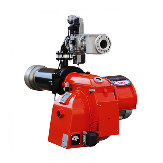
ITALIANO DESCRIZIONE COMPONENTI 1 Testa di combustione 2 Guarnizione 3 Valvola farfalla gas 4.1) Servomotore regolazione gas 4 Valvola funzionamento 5 Valvola di sicurezza 6 Pressostato gas di minima e controllo tenuta gas 7 Display BT 320 8 Vite di regolazione aria alla testa di combustione 9 Pressostato aria 10 Servomotore regolazione aria 11 Quadro elettrico... -
Page 12: Dimensioni Di Ingombro
ITALIANO DIMENSIONI DI INGOMBRO Modello BGN 450 ME 1660 BGN 510 ME 1660 Modello D min D max E Ø F Ø L min L max BGN 450 ME BGN 510 ME Modello N Ø BGN 450 ME BGN 510 ME... -
Page 13: Schema Di Principio Rampa Gas
ITALIANO SCHEMA DI PRINCIPIO RAMPA GAS Lo schema di principio della linea di alimentazione gas è riportato nella figura sotto. PERICOLO / ATTENZIONE Occorre installare, a monte della valvola gas, una valvola di intercettazione manuale e un giunto antivibrante, disposti secondo quanto indicato nello schema di principio. -
Page 14: Applicazione Del Bruciatore Alla Caldaia
ITALIANO APPLICAZIONE DEL BRUCIATORE ALLA CALDAIA MONTAGGIO GRUPPO TESTATA La testa del bruciatore viene imballata separatamente dal corpo bruciatore. Per infilare la flangia isolante (17) che deve essere interposta tra il bruciatore e la piastra di caldaia (18), occorre smontare il diffusore della testa del bruciatore. -
Page 15: Linea Di Alimentazione
ITALIANO LINEA DI ALIMENTAZIONE SCHEMA DI PRINCIPIO PER L'INSTALLAZIONE SARACINESCA-FILTRO-STABILIZZATORE GIUNTO Lo schema di principio della linea di alimentazione gas è riportato ANTIVIBRANTE-RACCORDO APRIBILE. nella figura sotto. Nel caso di rampa gas dotata di regolazione di pressione non incorporato in una valvola monoblocco, riteniamo utile esporre i seguenti consigli pratici relativi all'installazione degli accessori sulla tubazione del gas in prossimità... -
Page 16: Collegamenti Elettrici
ITALIANO COLLEGAMENTI ELETTRICI • Tutti i collegamenti devono essere eseguiti con filo elettrico flessibile. • La sezione minima dei conduttori deve essere di 1.5 mm². • Le linee elettriche devono essere distanziate dalle parti calde. • L’installazione del bruciatore è consentita solo in ambienti con grado di inquinamento 2 come indicato nell’allegato M della norma EN 60335-1:2008-07. - Page 17 ITALIANO • Per richiudere il coperchio del quadro elettrico, avvitare le viti (1) esercitando una coppia di serraggio di circa 5 Nm per assicurare la corretta tenuta. Per accedere al pannello comandi (8), fare scorrere lo sportellino trasparente (7) per un breve tratto nella direzione della freccia indicata in figura esercitando una leggera pressione con un utensile (esempio cacciavite) nella direzione delle freccce, farlo scorrere per un breve trato e separarlo dal coperchio.
-
Page 18: Descrizione Del Funzionamento Adue Stadi Progressivi
ITALIANO DESCRIZIONE DEL FUNZIONAMENTO A CAUTELA / AVVERTENZE DUE STADI PROGRESSIVI La camma elettronica comanda il bruciatore, azionando il servomotore dell'aria comburente, del gas e, se presente I bruciatori ad aria soffiata con modulazione elettronica sono adatti l'inverter del motore ventola, secondo una curva di lavoro per funzionare su focolari in forte pressione o in depressione avente dieci punti impostati (vedi tabella regolazione curva). -
Page 19: Accensione E Regolazione
ITALIANO ACCENSIONE E REGOLAZIONE • Applicare un manometro con scala adeguata alla presa di pressione prevista sul pressostato gas, se l'entità della • Verificare che la tensione della linea elettrica corrisponda a pressione prevista lo consente è preferibile utilizzare uno quella richiesta dal costruttore e, che tutti i collegamenti elettrici strumento a colonna d'acqua. -
Page 20: Misurazione Della Corrente Di Ionizzazione
ITALIANO Per accertare il corretto funzionamento del pressostato aria CAUTELA / AVVERTENZE occorre, con bruciatore acceso in 1° stadio, aumentare il valore Controllare che l’accensione avvenga regolarmente. Nel di regolazione fino a verificarne l'intervento a cui deve conseguire caso in cui il miscelatore sia troppo in avanti, può succedere l'immediato arresto in "blocco"... -
Page 21: Schema Di Regolazione Testa Di Combustione E Distanza Disco Elettrodi
ITALIANO SCHEMA DI REGOLAZIONE TESTA DI COMBUSTIONE E DISTANZA DISCO ELETTRODI 1 - Elettrodo ionizzazione 6 - Entrata gas 2 - Elettrodo accensione 7 - Flangia attacco bruciatore 3 - Disco fiamma 8 - Pomello regolazione testa di combustione. 4 - Miscelatore Spostarsi in avanti per aprire il passaggio aria tra disco e 5 - Tubo mandata gas diffusore. -
Page 22: Manutenzione
ITALIANO MANUTENZIONE Effettuare almeno una volta all’anno e comunque in conformità alle norme vigenti, l’analisi dei gas di scarico della combustione verificando la correttezza dei valori di emissioni. Al termine della stagione di riscaldamento, eseguire le seguenti operazioni: • Pulire le serrande aria, il pressostato aria con presa di pressione ed il relativo tubo se presenti. -
Page 23: Tempi Di Manutenzione
ITALIANO TEMPI DI MANUTENZIONE TESTA DI COMBUSTIONE CONTROLLO VISIVO, INTERGITA CERAMICHE. SMERIGLIATURA ELETTRODI ESTREMITA, VERIFICARE DISTANZA, VERIFICARE ANNUO CONNESSIONE ELETTRICA. CONTROLLO VISIVO INTEGRITA EVENTUALI DEFORMAZIONI, DISCO FIAMMA ANNUO PULIZIA, CONTROLLO VISIVO, INTERGITA CERAMICHE. SMERIGLIATURA SONDA DI IONIZZAZIONE ESTREMITA, VERIFICARE DISTANZA, VERIFICARE ANNUO CONNESSIONE ELETTRICA. -
Page 24: Istruzioni Per L'accertamento Delle Cause Di Irregolarità Nel Funzionamento E La Loro Eliminazione
ITALIANO ISTRUZIONI PER L'ACCERTAMENTO DELLE CAUSE DI IRREGOLARITÀ NEL FUNZIONAMENTO E LA LORO ELIMINAZIONE POSSIBILE CAUSA RIMEDIO IRREGOLARITÁ Invertire l'alimentazione (lato 230V) del trasformatore di accensione e verificare Disturbo della corrente di con micro-amperometro analogico. ionizzazione da parte del Sostituire il sensore fiamma. trasformatore di accensione. -
Page 25: Schemi Elettrici
ITALIANO SCHEMI ELETTRICI 23 / 26 0006160036_201504... - Page 26 ITALIANO 24 / 26 0006160036_201504...
- Page 27 ITALIANO 25 / 26 0006160036_201504...
- Page 28 ITALIANO GNYE VERDE / GIALLO APPARECCHIATURA FOTORESISTENZA / ELETTRODO DI IONIZZAZIONE / FOTOCELLULA UV BRUNO SONDA DI PRESSIONE NERO SONDA DI TEMPERATURA CONNETTORE NERO CON SOVRASTAMPA RELE’ TERMICO FU1÷4 FUSIBILI SPIA BLOCCO ESTERNA / LAMPADA FUNZIONAMENTO RESISTENZE AUSILIARIE SPIA DI FUNZIONAMENTO CONTATTORE MOTORE VENTOLA MOTORE VENTOLA “REGOLATORE ELETTRONICO“...
- Page 29 ENGLISH ENGLISH INDEX Instructions for use in safe conditions ..............................pag 3 Technical specifications ..................................pag 6 Supplied material..................................pag 7 Burner identification plate ................................pag 7 First start up recording data ...............................pag 7 Technical functional characteristics ............................pag 8 Operating range ..................................pag 8 Component description ................................pag 9 Electrical panel ...................................pag 9 Overall dimensions ...................................pag 10 Gas train principle diagram ..............................
- Page 30 ENGLISH DECLARATION OF CONFORMITY CE0085: DVGW CERT GmbH, Josef-Wirmer Strasse 1-3-53123 Bonn (D) We hereby declare under our own responsibility, that our domestic and industrial blown air burners fired by gas, oil and dual fuel, series: BPM...; BGN…; BT…; BTG…; BTL…; TBML...; Comist…; GI…; GI…Mist; Minicomist…; PYR…; RiNOx…; Spark...; Sparkgas...; TBG...;TBL...;...
- Page 31 ENGLISH INSTRUCTIONS FOR USE IN SAFE GENERAL INSTRUCTIONS • The device is not suitable to be used by persons (including CONDITIONS children) with reduced physical, sensory or mental capacities, or lack of experience or knowledge. PURPOSE OF THE MANUAL • such persons can use the device only if they can benefit, through The manual purpose is to contribute to the safe use of the the intermediation of a responsible person, of information product, indicating the conduct and behaviour required to prevent...
- Page 32 ENGLISH SAFETY INSTRUCTIONS FOR INSTALLATION INSTRUCTIONS FOR START-UP, INSPECTION, USE AND MAINTENANCE • The equipment must be installed in a suitable area with adequate ventilation according to the standards and regulations in force. • Start-up, inspection and maintenance of the equipment must •...
- Page 33 ENGLISH INSTRUCTIONS ON ELECTRICAL SAFETY • If the burner repeatedly shuts down in lock-out, do not keep trying to manually reset it but call a qualified technician to solve • Check that the equipment is properly grounded according to the the unexpected problem.
- Page 34 Baltur's laboratory environment conditions and cannot be compared to measurements carried out in different locations. Acoustic pressure was obtained characterizing Baltur's laboratory with a sample source, this measurement has an accuracy of class 2 (engineering class) with a standard deviation f 1.5 dB(A).
- Page 35 ENGLISH SUPPLIED MATERIAL MODEL BGN 450 ME BGN 510 ME INSULATING SEAL STUD BOLTS No. 4 M20 No. 4 M20 HEXAGONAL NUTS No. 4 M20 No. 4 M20 FLAT WASHERS No. 4 Ø20 No. 4 Ø20 INSULATING ROPE BURNER IDENTIFICATION PLATE...
- Page 36 • Electric system with protection class IP54.Gas train outlet from above. OPERATING RANGE mbar BGN 450 ME BGN 510 ME kW x 1000 IMPORTANT The operating ranges are obtained from test boilers corresponding to Standard EN676 and are indicative of the burner-boiler combination.
- Page 37 ENGLISH COMPONENT DESCRIPTION 1 Combustion head 2 Seal 3 Gas throttle valve 4.1) Gas regulation servomotor 4 Operating valve 5 Safety valve 6 Minimum gas pressure switch and gas leak control 7 BT 320 display 8 Screw for regulation of the air supply to the combustion head 9 Air pressure switch 10 Air regulation servomotor 11 Electrical panel...
- Page 38 ENGLISH OVERALL DIMENSIONS Model BGN 450 ME 1660 BGN 510 ME 1660 Model D min D max E Ø F Ø L min L max BGN 450 ME BGN 510 ME Model N Ø BGN 450 ME BGN 510 ME...
- Page 39 ENGLISH GAS TRAIN PRINCIPLE DIAGRAM The basic diagram of the gas supply line is shown in the figure below. DANGER / CAUTION Install a manual on/off valve upstream of the gas valve according to the layout shown in the diagram illustrating the gas train principle.
- Page 40 ENGLISH BURNER CONNECTION TO THE BOILER ASSEMBLING THE HEAD UNIT The burner head is packaged separately from the body of the burner. Remove the combustion head diffuser to insert the insulating flange -17 between the burner and the boiler plate -18. Anchor the burner to the boiler door as follows: •...
- Page 41 ENGLISH SUPPLY LINE GENERAL DIAGRAM FOR THE INSTALLATION OF SHUTTER-FILTER-STABILIZER-VIBRATION-PROOF JOINT- The basic diagram of the gas supply line is shown in the figure OPENABLE FITTING. below. If the gas train is equipped with a pressure regulation device not integrated in a monoblock valve, follow the instructions below to install the accessories on the gas pipe near the burner: •...
- Page 42 ENGLISH ELECTRICAL CONNECTIONS • It is advisable to make all connections with flexible electric wire. • Conductor minimum section must be 1.5 mm². • Electrical lines must be kept away from hot parts. • The burner installation is allowed only in environments with pollution degree 2 as indicated in annex M of the EN 60335- 1:2008-07 regulation.
- Page 43 ENGLISH • To reclose the electrical panel lid, fix the screws (1) with a torque of about 5 Nm to ensure the correct seal. To gain access to the control panel (8), slide the transparent door (7) for a short distance following the direction on the arrow indicated in the figure exerting slight pressure with a tool (e.g.
- Page 44 ENGLISH DESCRIPTION OF PROGRESSIVE TWO- CAUTION / WARNING STAGE OPERATION The electronic cam controls the burner, activating the combustion air, gas servomotor and the fan motor, if the Blown air burners with electronic modulation may be used on inverter is fitted, according to a curve that has ten points set hearths under strong pressure or in a vacuum, according to the (see curve regulation table).
- Page 45 ENGLISH STARTING UP AND REGULATION • Apply a pressure gauge of appropriate scale to the pressure intake on the gas pressure switch. If the foreseen amount of • Check that thee voltage on the mains meets the manufacturer pressure allows it, it is better to use a water column instrument. requirements and that all electrical connections made at the Do not use dial instruments for average pressures.
- Page 46 ENGLISH To ensure correct operation of the air pressure switch you must, CAUTION / WARNING with burner on and in 1st stage, increase its regulation value until Check that the ignition takes place properly. In the event the burner triggers and then it immediately “locks-out”. that the mixer is too far forward, it may happen that the Reset the burner by pressing the appropriate button and readjust outgoing air speed is so high that ignition is difficult.
- Page 47 ENGLISH DIAGRAM FOR REGULATION OF COMBUSTION HEAD AND ELECTRODE DISK DISTANCE 1 - Ionisation electrode 6 - Gas inlet 2 - Ignition electrode 7 - Burner connection flange 3 - Flame disk 8 - Combustion head adjustment knob. 4 - Mixer Move forward to open the air passage between disk and 5 - Gas delivery pipe diffuser.
- Page 48 ENGLISH MAINTENANCE Analyse combustion gases and check that the emission values are correct at least once a year, in compliance with current law. Carry out the following operations at the end of the heating season: • Clean air dampers, the air pressure switch with pressure port and the relevant pipe (if fitted).
- Page 49 ENGLISH MAINTENANCE TIME COMBUSTION HEAD VISUAL INSPECTION OF THE INTEGRITY OF CERAMICS. ELECTRODES TIP GRINDING, CHECK DISTANCE, CHECK ELECTRICAL YEARLY CONNECTION. INTEGRITY VISUAL INSPECTION FOR POSSIBLE WARPING, FLAME DISK YEARLY CLEANING VISUAL INSPECTION OF THE INTEGRITY OF CERAMICS. IONISATION PROBE TIP GRINDING, CHECK DISTANCE, CHECK ELECTRICAL YEARLY CONNECTION.
- Page 50 ENGLISH TROUBLESHOOTING INSTRUCTIONS POSSIBLE CAUSE REMEDY ANOMALY Invert the ignition transformer power supply (230V side) and check using an Disturbance to ionisation current analogue micro-ammeter. from the ignition transformer. Replace flame sensor. Flame sensor (ionisation probe) Correct the position of the flame inefficient.
- Page 51 ENGLISH WIRING DIAGRAMS 23 / 26 0006160036_201504...
- Page 52 ENGLISH 24 / 26 0006160036_201504...
- Page 53 ENGLISH 25 / 26 0006160036_201504...
- Page 54 ENGLISH GNYE GREEN / YELLOW EQUIPMENT PHOTORESISTOR / IONISATION ELECTRODE / UV BLUE PHOTOCELL BROWN PRESSURE PROBE BLACK TEMPERATURE PROBE BLACK CONNECTOR WITH OVERPRINT THERMAL RELAY FU1÷4 FUSES EXTERNAL LOCK INDICATOR LIGHT/ AUXILIARY HEATING ELEMENT OPERATION LAMP OPERATION INDICATOR LIGHT FAN MOTOR CONTACTOR FAN MOTOR ELECTRONIC REGULATOR...
- Page 56 BALTUR S.P.A. Via Ferrarese, 10 44042 Cento (Fe) - Italy Tel. +39 051-6843711 Fax. +39 051-6857527/28 www.baltur.it info@baltur.it Il presente catalogo riveste carattere puramente indicativo. La casa, pertanto, si riserva ogni possibilità di modifica dei dati tecnici e di quant'altro in esso riportato.
Need help?
Do you have a question about the BGN 450 ME and is the answer not in the manual?
Questions and answers