Table of Contents
Advertisement
Available languages
Available languages
Quick Links
ITALIANO
Manuale istruzioni per l'installazione,
l'uso e la manutenzione
Installation, use and maintenance
instruction manual
ISTRUZIONI ORIGINALI (IT)
ORIGINAL INSTRUCTIONS (IT)
BRUCIATORI DI GAS A DUE STADI PROGRESSIVI / MODULANTI
PROGRESSIVE/MODULATING TWO-STAGE GAS BURNERS
IT
EN
CON CAMMA MECCANICA
WITH MECHANICAL CAM
GI 500 MC
GI 700 MC
0006160064_201510
Advertisement
Table of Contents

Related Manuals for baltur GI 700 MC


Summary of Contents for baltur GI 700 MC
- Page 1 BRUCIATORI DI GAS A DUE STADI PROGRESSIVI / MODULANTI CON CAMMA MECCANICA PROGRESSIVE/MODULATING TWO-STAGE GAS BURNERS WITH MECHANICAL CAM ITALIANO GI 500 MC Manuale istruzioni per l'installazione, l'uso e la manutenzione GI 700 MC Installation, use and maintenance instruction manual ISTRUZIONI ORIGINALI (IT) ORIGINAL INSTRUCTIONS (IT) 0006160064_201510...
-
Page 3: Table Of Contents
ITALIANO ITALIANO SOMMARIO Avvertenze per l'uso in condizioni di sicurezza ..........................pag 3 Caratteristiche tecniche ..................................pag 6 Materiale a corredo per fissaggio bruciatore alla caldaia ......................pag 7 Targa identificazione bruciatore..............................pag 7 Dati registrazione prima accensione ............................pag 7 Descrizione componenti ................................pag 8 Campo di lavoro ..................................pag 8 Dimensioni di ingombro ................................pag 9 Caratteristiche costruttive .................................pag 10... - Page 4 ITALIANO DICHIARAZIONE DI CONFORMITÀ CE0085: DVGW CERT GmbH, Josef-Wirmer Strasse 1-3-53123 Bonn (D) Dichiariamo che i nostri bruciatori ad aria soffiata di combustibili luquidi, gassosi e misti, domestici e industriali, serie: BPM...; BGN…; BT…; BTG…; BTL…; TBML...; Comist…; GI…; GI…Mist; Minicomist…; PYR…; RiNOx…; Spark...; Sparkgas...; TBG...;TBL...;...
-
Page 5: Avvertenze Per L'uso In Condizioni Di Sicurezza
ITALIANO AVVERTENZE PER L'USO IN CONDIZIONI (bambini compresi) le cui capacità fisiche, sensoriali o mentali siano ridotte, oppure con mancanza di esperienza o di cono- DI SICUREZZA scenza. • l'uso dell'apparecchio è consentito a tali persone solo nel caso SCOPO DEL MANUALE in cui possano beneficiare, attraverso l'intermediazione di una Il manuale si propone di contribuire all'utilizzo sicuro del prodotto persona responsabile, di informazioni relative alla loro sicurez-... - Page 6 • Prima di avviare il bruciatore e almeno una volta all’anno, far ef- • L’eventuale riparazione dei prodotti dovrà essere effettuata so- fettuare da personale professionalmente qualificato le seguenti lamente da un centro di assistenza autorizzato da BALTUR o operazioni: dal suo distributore locale, utilizzando esclusivamente ricambi - Tarare la portata di combustibile del bruciatore secondo la originali.
- Page 7 ITALIANO Avvertenze particolari per l’uso del gas. che il filo possa venire a contatto con parti metalliche. • Verificare che la linea di adduzione e la rampa siano conformi • L’alimentazione elettrica del bruciatore deve prevedere il neutro alle norme e prescrizioni vigenti. a terra.
-
Page 8: Caratteristiche Tecniche
Baltur e non è confrontabile con misure effettuate in siti diversi. *** La potenza sonora è stata ottenuta caratterizzando il laboratorio Baltur con un sorgente campione; tale misura ha un'accuratez- za di categoria 2 (engineering class) con deviazione standard pari a 1.5 dB(A). -
Page 9: Materiale A Corredo Per Fissaggio Bruciatore Alla Caldaia
ITALIANO MATERIALE A CORREDO PER FISSAGGIO BRUCIATORE ALLA CALDAIA MODELLO GI 500 MC GI 700 MC GUARNIZIONE ISOLANTE PRIGIONIERI N°6 M20 N° 6 M20 DADI ESAGONALI N°6 M20 N° 6 M20 RONDELLE PIANE N°6 Ø20 N° 6 Ø20 TARGA IDENTIFICAZIONE BRUCIATORE... -
Page 10: Descrizione Componenti
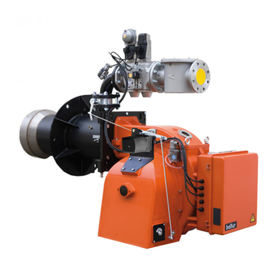
ITALIANO DESCRIZIONE COMPONENTI 1 Testa di combustione 2 Guarnizione 3 Flangia attacco bruciatore 4 Valvola farfalla gas 5 Vite di regolazione aria alla testa di combustione 6 Pressostato aria 7 Servomotore camma meccanica 8 Quadro elettrico 9 Cerniera 10 Motore ventola 11 Trasformatore d'accensione 12 Targa identificazione bruciatore CAMPO DI LAVORO... -
Page 11: Dimensioni Di Ingombro
ITALIANO DIMENSIONI DI INGOMBRO Modello GI 500 MC 1040 1830 GI 700 MC 1065 1835 Modello E Ø F Ø LØ GI 500 MC GI 700 MC Modello N Ø GI 500 MC GI 700 MC 9 / 36 0006160064_201510... -
Page 12: Caratteristiche Costruttive
ITALIANO CARATTERISTICHE COSTRUTTIVE CARATTERISTICHE TECNICO FUNZIONALI I bruciatori risultano composti da: • Bruciatore di gas conforme alle normative europee EN 676 • Parte ventilante in lega leggera d'alluminio. ed alle Direttive Europee 2006/42/CE; 2006/95/CE; 97/23/CE; • Ventilatore centrifugo per alte prestazioni. 2004/108/CE. -
Page 13: Applicazione Del Bruciatore Alla Caldaia
ITALIANO APPLICAZIONE DEL BRUCIATORE ALLA CALDAIA MONTAGGIO GRUPPO TESTATA La testa di combustione viene imballata separatamente dal corpo ventilante. Fissare il gruppo testa al portellone caldaia nel seguente modo: • Posizionare sul canotto le guarnizioni isolanti (13). • Fissare la flangia del gruppo testa (14) alla caldaia (19) tramite i prigionieri, le rondelle, e i relativi dadi in dotazione (7) CAUTELA / AVVERTENZE Sigillare completamente con materiale idoneo lo spazio tra... -
Page 14: Schema Di Principio Rampa Gas
ITALIANO MONTAGGIO RAMPA GAS La rampa gas è omologata secondo normativa EN 676 e viene fornita separatamente. Sono possibili diverse soluzioni di montaggio (1), (2), (3) , della rampa gas. SCHEMA DI PRINCIPIO RAMPA GAS PERICOLO / ATTENZIONE Occorre installare, a monte della valvola gas, una valvola di intercettazione manuale e un giunto anti-vibrante, disposti secondo quanto indicato nello schema di principio. -
Page 15: Collegamenti Elettrici
ITALIANO COLLEGAMENTI ELETTRICI • Tutti i collegamenti devono essere eseguiti con filo elettrico flessibile. • La sezione minima dei conduttori deve essere di 1.5 mm². • Le linee elettriche devono essere distanziate dalle parti calde. • L’installazione del bruciatore è consentita solo in ambienti con grado di inquinamento 2 come indicato nell’allegato M della nor- ma EN 60335-1:2008-07. -
Page 16: Descrizione Del Funzionamento
ITALIANO DESCRIZIONE DEL FUNZIONAMENTO La rampa gas in dotazione è composta da una valvola di sicu- rezza in versione ON/OFF e da una valvola principale a singolo stadio ad apertura lenta. La regolazione della portata di combustibile in primo e in secon- do stadio è... - Page 17 ITALIANO - Correggere se necessario l’erogazione di aria comburente operando sulla vite/viti (11). • Il pressostato aria ha lo scopo di impedire l’apertura delle val- vole gas se la pressione dell’aria non è quella prevista. Il pres- sostato deve quindi essere regolato per intervenire chiudendo il contatto quando la pressione dell’aria nel bruciatore raggiunge il valore sufficiente.
-
Page 18: Accensione E Regolazione
ITALIANO ACCENSIONE E REGOLAZIONE REGOLAZIONE DELLA POTENZA IN SECONDO STADIO Dopo aver completato la regolazione della potenza di accensione, ruotare il deviatore (9) in posizione massimo (MAX) in modo da ISTRUZIONI PER IL FUNZIONAMENTO IN MODALITÀ MA- raggiungere la massima erogazione di aria e gas.Verificare che NUALE DEL BRUCIATORE. - Page 19 ITALIANO - Correggere se necessario l’erogazione di aria comburente operando sulla vite/viti (11). • Il pressostato aria ha lo scopo di impedire l’apertura delle val- vole gas se la pressione dell’aria non è quella prevista. Il pres- sostato deve quindi essere regolato per intervenire chiudendo il contatto quando la pressione dell’aria nel bruciatore raggiunge il valore sufficiente.
-
Page 20: Misurazione Della Corrente Di Ionizzazione
ITALIANO MISURAZIONE DELLA CORRENTE DI IONIZZAZIONE Il bruciatore dà una corrente nettamente superiore, tale da non richiedere normalmente alcun controllo. LFL 1.3xx REGOLAZIONE DELL'ARIA SULLA TESTA DI COMBUSTIO- La testa di combustione è dotata di un dispositivo di regolazione che permette di aprire o chiudere il passaggio dell’aria tra il disco e la testa. Chiudendo il passaggio si riesce così ad ottenere, un’elevata pressione a monte del disco anche con le basse portate. L’elevata velocità e turbolenza dell’aria consente una migliore penetrazione della stessa nel combustibile e quindi, un’ottima miscela e stabilità di fiamma. Può essere indispensabile avere un’elevata pressione d’aria a monte del disco, per evitare pulsazioni di fiamma, questa condizione è praticamente indispensabile quando il bruciatore lavora su focolare pressurizzato e/o ad alto carico termico. CAUTELA / AVVERTENZE Controllare che l'accensione avvenga regolarmente spo- stando per gradi il pomello di comando e fissaggio diffu-... -
Page 21: Apparecchiatura Di Controllo Ecomando Lfl 1.333
ITALIANO APPARECCHIATURA DI CONTROLLO E COMANDO LFL 1.333 Apparecchi di comando e controllo per bruciatori ad aria soffiata da medie a grandi potenzialità (a servizio intermittente) per bru- ciatori a 1 o 2 stadi o modulanti con supervisione della pressione dell’aria per il comando della serranda aria. - Page 22 ITALIANO COLLEGAMENTI ELETTRICI Per il collegamento della valvola di sicurezza vale lo schema del produttore del bruciatore LEGENDA Contatto commutatore di fine corsa per la posizione APER- Valvola del combustibile a regolazione continua TA della serranda aria Fusibile Segnalazione a distanza di un arresto di blocco (allarme) Servomotore serranda aria Relè...
- Page 23 ITALIANO Note sul programmatore sequenza del programmatore segnali in uscita sulla morsettiera Legenda tempi Sec. 31,5 Tempo di pre-ventilazione con serranda aria aperta Tempo di sicurezza Tempo di sicurezza o primo tempo di sicurezza con bruciatori che utilizzano bruciatori pilota Tempo di pre-accensione corto (trasformatore di accensione sul morsetto 16) Tempo di pre-accensione lungo (trasformatore di accensione sul morsetto 15) Intervallo tra l'inizio di t2' ed il consenso alla valvolasul morsetto 19 con t2...
- Page 24 ITALIANO t2', t3', t4' : PROGRAMMA DI COMANDO IN CASO DI INTERRUZIONE E INDICAZIONE DELLA POSIZIONE DI INTERRUZIONE Questi intervalli sono validi solo per gli apparecchi di coman- do e controllo bruciatore serie 01, ovvero LFL.335, LFL1.635, In linea di principio, in caso di interruzione di qualsiasi natura, LFL1.638.
- Page 25 ITALIANO Se si verifica un arresto di blocco in qualsiasi momento tra la partenza e la pre-accensione senza simbolo, la causa è general- mente rappresentata da un segnale di fiamma prematuro, ovvero anomalo, causato ad esempio dall’auto-accensione di un tubo UV. INDICAZIONE DI ARRESTO Programma di avviamento b-b'...
-
Page 26: Particolare Motore Sqm 40 Di Comando Modulazione Per Regolazione Cammes
ITALIANO PARTICOLARE MOTORE SQM 40 DI CO- REGOLAZIONE SERVOMOTORE ARIA SQN72.4C4A20 MANDO MODULAZIONE PER REGOLA- ZIONE CAMMES 0002938080 Camma regolazione aria 2° fiamma (120°) APERTURA MASSIMA ARIA (130°) Chiusura totale aria (bruciatore fermo) (0°) CHIUSURA TOTALE ARIA (BRUCIATORE FERMO) (0°) III Camma regolazione aria 1°fiamma (10°) III APERTURA ARIA D'ACCENSIONE (MAGGIORE DI CAM- IV Camma aria accensione (30°) IV >... -
Page 27: Schema Di Regolazione Testa Di Combustione E Distanza Disco Elettrodi
SCHEMA DI REGOLAZIONE TESTA DI COMBUSTIONE E DISTANZA DISCO ELETTRODI 1 - Elettrodo ionizzatore 2 - Elettrodo accensione GI 500 MC 19÷59 3 - Disco fiamma GI 700 MC 19÷59 4 - Miscelatore 5 - Tubo mandata gas 6 - Entrata gas 7 - Flangia attacco bruciatore 8 - Pomello regolazione testa di combustione. -
Page 28: Manutenzione
ITALIANO MANUTENZIONE Effettuare almeno una volta all’anno e comunque in conformità alle norme vigenti, l’analisi dei gas di scarico della combustione verificando la correttezza dei valori di emissioni. Al termine della stagione di riscaldamento, eseguire le seguenti operazioni: • Pulire le serrande aria, il pressostato aria con presa di pressio- ne ed il relativo tubo se presenti. -
Page 29: Tempi Di Manutenzione
ITALIANO TEMPI DI MANUTENZIONE TESTA DI COMBUSTIONE CONTROLLO VISIVO, INTERGITA CERAMICHE. SMERIGLIATURA ESTREMITA, ELETTRODI ANNUO VERIFICARE DISTANZA, VERIFICARE CONNESSIONE ELETTRICA. DISCO FIAMMA CONTROLLO VISIVO INTEGRITA EVENTUALI DEFORMAZIONI, PULIZIA, ANNUO CONTROLLO VISIVO, INTERGITA CERAMICHE. SMERIGLIATURA ESTREMITA, SONDA DI IONIZZAZIONE ANNUO VERIFICARE DISTANZA, VERIFICARE CONNESSIONE ELETTRICA. COMPONENTI TESTA COMBUSTIONE CONTROLLO VISIVO INTEGRITA EVENTUALI DEFORMAZIONI, PULIZIA, ANNUO... -
Page 30: Precisazioni Sull'uso Del Propano
ITALIANO PRECISAZIONI SULL'USO DEL PROPANO PERICOLO / ATTENZIONE La potenza massima e minima (kW) del bruciatore, è consi- • Valutazione, indicativa, del costo di esercizio; derata con combustibile metano che coincide approssimati- - 1 m3 di gas liquido in fase gassosa ha un potere calorifico vamente con quella del propano. -
Page 31: Schema Di Principio Per Riduzione Pressione G.p.l. A Due Stadi Per Bruciatore Oppure Caldaia
ITALIANO SCHEMA DI PRINCIPIO PER RIDUZIONE PRESSIONE G.P.L. A DUE STADI PER BRUCIATORE OPPURE CALDAIA Manometro e presa di pressione Riduttore di 1° salto Riduttore di 2° salto Uscita ~ 1,5 bar Uscita ~ 30 mbar Portata ~ il doppio del massimo richiesto Portata ~ il doppio del massimo richiesto dall’utilizzatore dall’utilizzatore... -
Page 32: Schema Di Installazione Con Vaporizzatore
ITALIANO SCHEMA DI INSTALLAZIONE CON VAPORIZZATORE A Eventuale collegamento fase gas di emergenza Specifica materiali B Vaporizzatore • Valvola di ripresa liquido C Serbatoio • Rubinetto erogazione liquido con limitatore di flusso. D Gruppo riduzione 1° salto • Raccordi in acciaio con codolo a saldare e rondella rame. Avvertenze •... -
Page 33: Istruzioni Per L'accertamento Delle Cause Di Irregolarità Nel Funzionamento E La Loro Eliminazione
ITALIANO ISTRUZIONI PER L'ACCERTAMENTO DELLE CAUSE DI IRREGOLARITÀ NEL FUNZIONA- MENTO E LA LORO ELIMINAZIONE POSSIBILE CAUSA RIMEDIO IRREGOLARITÁ Invertire l'alimentazione (lato 230V) del trasformatore di accensione e verificare Disturbo della corrente di ionizza- con micro-amperometro analogico. zione da parte del trasformatore di Sostituire il sensore fiamma. -
Page 34: Schemi Elettrici
ITALIANO SCHEMI ELETTRICI 32 / 36 0006160064_201510... - Page 35 ITALIANO 33 / 36 0006160064_201510...
- Page 36 ITALIANO 34 / 36 0006160064_201510...
- Page 37 ITALIANO GNYE VERDE / GIALLO APPARECCHIATURA CONTROLLO TENUTA VALVOLE FOTORESISTENZA / ELETTRODO DI IONIZZAZIONE / NERO FOTOCELLULA UV BRUNO RELE’ TERMICO CONNETTORE NERO CON SOVRASTAMPA FU1÷4 FUSIBILI SPIA DI FUNZIONAMENTO “SPIA DI BLOCCO“ “SPIA DI BLOCCO LDU11“ “CONTATTORE TRIANGOLO“ CONTATTORE ESTERNO CONTATTORE DI LINEA TEMPORIZZATORE CONTATTORE DI STELLA...
- Page 38 ITALIANO 36 / 36 0006160064_201510...
- Page 39 ENGLISH ENGLISH INDEX Instructions for use in safe conditions ..............................pag 3 Technical specifications ..................................pag 6 Material provided to secure the burner to the boiler ........................pag 7 Burner identification plate ................................pag 7 First start up recording data ...............................pag 7 Component description ................................pag 8 Operating range ..................................pag 8 Overall dimensions ..................................pag 9 Design characteristics ................................pag 10...
- Page 40 ENGLISH DECLARATION OF CONFORMITY CE0085: DVGW CERT GmbH, Josef-Wirmer Strasse 1-3-53123 Bonn (D) We hereby declare under our own responsibility, that our domestic and industrial blown air burners fired by gas, oil and dual fuel, series: BPM...; BGN…; BT…; BTG…; BTL…; TBML...; Comist…; GI…; GI…Mist; Minicomist…; PYR…; RiNOx…; Spark...; Sparkgas...; TBG...;TBL...;...
- Page 41 ENGLISH INSTRUCTIONS FOR USE IN SAFE CON- gh the intermediation of a responsible person, of information regarding their safety, of surveillance, of instructions concerning DITIONS its use. • Children should be supervised to ensure that they do not play PURPOSE OF THE MANUAL with the device.
- Page 42 Contact only qualified personnel. sions according to the regulations in force. • Any product repairs must only be carried out by BALTUR autho- - Check the regulation and safety devices are working rised assistance centres or its local retailer using only original properly.
- Page 43 ENGLISH Special instructions for using gas. to the burner. • Check that the feed line and the train comply with current stan- • The use of any components that use electricity means that cer- dards and regulations. tain fundamental rules have to followed, including the following: •...
-
Page 44: Technical Specifications
Baltur's laboratory environment conditions and cannot be compared to measurements carried out in different locations. Acoustic pressure was obtained characterizing Baltur's laboratory with a sample source, this measurement has an accuracy of class 2 (engineering class) with a standard deviation f 1.5 dB(A). - Page 45 ENGLISH MATERIAL PROVIDED TO SECURE THE BURNER TO THE BOILER MODEL GI 500 MC GI 700 MC INSULATING SEAL STUD BOLTS No.6 M20 No. 6 M20 HEXAGONAL NUTS No.6 M20 No. 6 M20 FLAT WASHERS No.6 Ø20 No. 6 Ø20...
- Page 46 ENGLISH COMPONENT DESCRIPTION 1 Combustion head 2 Seal 3 Burner connection flange 4 Gas throttle valve 5 Screw for regulation of the air supply to the combustion head 6 Air pressure switch 7 Mechanical cam servomotor 8 Electrical panel 9 Hinge 10 Fan motor 11 Ignition transformer 12 Burner identification plate...
- Page 47 ENGLISH OVERALL DIMENSIONS Model GI 500 MC 1040 1830 GI 700 MC 1065 1835 Model E Ø F Ø LØ GI 500 MC GI 700 MC Model N Ø GI 500 MC GI 700 MC 9 / 36 0006160064_201510...
- Page 48 ENGLISH DESIGN CHARACTERISTICS TECHNICAL FUNCTIONAL CHARACTERISTICS Burners are composed by: • Gas burner compliant with European Standards EN 676 and • Ventilating part in light aluminium alloy. European Directives 006/42/EC; 2006/95/EC; 97/23/EC; • Centrifugal fan for high performances. 2004/108/EC. • Intake air conveyor. •...
- Page 49 ENGLISH BURNER CONNECTION TO THE BOILER ASSEMBLING THE HEAD UNIT The combustion head is packaged separately from the body of the burner. Anchor the head unit to the boiler door as follows: • Position the insulating seals -13 on the sleeve. •...
- Page 50 ENGLISH ASSEMBLING THE GAS TRAIN The EN 676 approved gas train is sold separately from the burner. The gas train can be assembled in different ways: -1, -2, -3 , of the gas train. GAS TRAIN PRINCIPLE DIAGRAM DANGER / CAUTION Install a manual on/off valve and a vibration-proof joint upstream of the gas valve according to the layout shown in the diagram illustrating the gas train principle.
-
Page 51: Electrical Connections
ENGLISH ELECTRICAL CONNECTIONS • It is advisable to make all connections with flexible electric wire. • Conductor minimum section must be 1.5 mm². • Electrical lines must be kept away from hot parts. • The burner installation is allowed only in environments with pollution degree 2 as indicated in annex M of the EN 60335- 1:2008-07 regulation. - Page 52 ENGLISH OPERATING DESCRIPTION The gas train supplied is composed of an ON/OFF safety valve and a single stage slow opening main valve. The fuel flow rate regulation in the first and second stage is carri- ed out by a streamlined throttle valve -6, activated by the electric servomotor -7.
- Page 53 ENGLISH - If necessary, correct the combustion air supply adjusting the screw(s) -11. • The air pressure switch prevents the opening of the gas valves if the air pressure is not the foreseen one. The pressure switch must therefore be adjusted to intervene and close the contact when the air pressure in the burner reaches a sufficient value.
- Page 54 ENGLISH STARTING UP AND REGULATION damaging it. • To regulate the air flow rate, use the screws -12, and correct the rotation angle of the air shutter and put it in the suitable position INSTRUCTIONS FOR MANUAL BURNER OPERATION. to guarantee the right quantity for the power burned. Combustion may be checked throughout the entire burner opera- •...
- Page 55 ENGLISH - If necessary, correct the combustion air supply adjusting the screw(s) -11. • The air pressure switch prevents the opening of the gas valves if the air pressure is not the foreseen one. The pressure switch must therefore be adjusted to intervene and close the contact when the air pressure in the burner reaches a sufficient value.
- Page 56 ENGLISH IONISATION CURRENT MEASUREMENT The burner provides a significantly higher current and therefore does not normally require any checks at all. LFL 1.3xx AIR REGULATION ON THE COMBUSTION HEAD The combustion head has a regulation device that allows the air passage between the disc and the combustion head to be opened or closed. Closing the passage, you can obtain high pressure upstream of the disc even at low flow rate. The high speed and turbulence of the air provides for its greater penetration into the fuel and therefore an excellent mixture and flame stability. High air pressure upstream of the disc may be necessary to prevent flame fluctuations, this is particularly essential when the burner works on the combustion chamber that is pressurised and/or at a high thermal load. CAUTION / WARNING Check that ignition takes place regularly, moving the diffu- ser control and fastening knob gradually until you reach a...
- Page 57 ENGLISH LFL 1.333 COMMAND AND CONTROL EQUIPMENT Command and control equipment for mid and large output blown- air burners (intermittent service) for 1 or 2 stage burners or for modulating burners with air pressure monitoring for air shutter control. The command and control equipment feature the EC mark accor- ding to the Gas and Electromagnetic Compatibility Directive.
- Page 58 ENGLISH ELECTRICAL CONNECTIONS For the safety valve connection refer to the drawing provided by the burner manufacturer Limit switch commutation contact for air shutter OPEN Fuel valve with continuous regulation position Fuse Remote signal of lock-out stop (alarm) Servomotor air shutter Main relay (operating relay) with “ar…”...
- Page 59 ENGLISH Notes on programmer - Programmer sequence Output signals on terminal board Time key Sec. 31,5 Pre-ventilation time with air shutter open Safety time Safety time or first safety time with burners that use pilot burners Short pre-ignition time (ignition transformer on terminal 16) Long pre-ignition time (ignition transformer on terminal 15) Time between beginning of t2’...
- Page 60 ENGLISH t2', t3', t4' : CONTROL PROGRAM IN CASE OF STOPPING AND INDI- CATION OF STOP POSITION Such time intervals are valid only for burner command and control equipment of series 01, i.e. LFL1.335, LFL1.635, LFL1.638. As a rule, in the event of any kind of stop, the fuel flow is immedia- They do not apply to burners of the series 02 since they have a tely cut off.
- Page 61 ENGLISH If a lock-out stop occurs between start-up and pre-ignition with no symbol, usually the cause is a premature flame, i.e. faulty, flame signal caused for example by the self-ignition of an UV pipe. SHUTDOWN INDICATION Start-up program b-b' “Trips” (without contact confirmation) b(b')-a Post-ventilation program LFL1..., series 01...
- Page 62 ENGLISH DETAIL OF THE MODULATION CONTROL SQN72.4C4A20 AIR SERVOMOTOR ADJUSTMENT MOTOR SQM 40 FOR CAM ADJUSTMENT 0002938080 MAXIMUM AIR OPENING (130°) 2nd flame air regulation cam (120°) TOTAL AIR CLOSURE (BURNER STOPPED)( 0°) Total air closure (burner stopped) (0°) III IGNITION AIR OPENING (GREATER THAN CAM) III 1st flame air regulation cam (10°) IV__TAB__MINIMUM AIR OPENING (LOWER THAN CAM III) IV Ignition air cam (30°) IV >...
- Page 63 DIAGRAM FOR REGULATION OF COMBUSTION HEAD AND ELECTRODE DISK DISTANCE 1 - Ionisation electrode 2 - Ignition electrode GI 500 MC 19÷59 3 - Flame disk GI 700 MC 19÷59 4 - Mixer 5 - Gas delivery pipe 6 - Gas inlet 7 - Burner connection flange 8 - Combustion head adjustment knob.
- Page 64 ENGLISH MAINTENANCE Analyse combustion gases and check that the emission values are correct at least once a year, in compliance with current law. Carry out the following operations at the end of the heating sea- son: • Clean air dampers, the air pressure switch with pressure port and the relevant pipe (if fitted).
- Page 65 ENGLISH MAINTENANCE TIME COMBUSTION HEAD VISUAL INSPECTION OF THE INTEGRITY OF CERAMICS. TIP GRINDING, ELECTRODES YEARLY CHECK DISTANCE, CHECK ELECTRICAL CONNECTION. FLAME DISK INTEGRITY VISUAL INSPECTION FOR POSSIBLE WARPING, CLEANING YEARLY VISUAL INSPECTION OF THE INTEGRITY OF CERAMICS. TIP GRINDING, IONISATION PROBE YEARLY CHECK DISTANCE, CHECK ELECTRICAL CONNECTION.
- Page 66 ENGLISH SPECIFICATIONS FOR PROPANE USE DANGER / CAUTION The burner's minimum and maximum output (kW) is rated • Operating costs approximate assessment; based on its use with methane gas which more or less cor- - 1 m3 of liquid gas in gaseous stage has a lower heating responds to the power values obtained with propane gas.
- Page 67 ENGLISH DIAGRAM ILLUSTRATING THE PRINCIPLE OF L.P.G. PRESSURE REDUCTION IN TWO STAGES FOR BURNER OR BOILER Pressure gauge and pressure intake 1st step reducer 2nd step reducer Output ~ 1.5 bar Output ~ 30 mbar Flow rate ~ double the maximum required by the Flow rate ~ double the maximum required by user the user...
- Page 68 ENGLISH INSTALLATION DIAGRAM WITH VAPORIZER A Any emergency gas phase connection Specific materials B Vaporizer • Liquid recovery valve C Tank • Liquid delivery cock with flow limiter. D 1st stage reducer unit • Steel fitting with welded tang and copper washer. Warnings •...
-
Page 69: Troubleshooting Instructions
ENGLISH TROUBLESHOOTING INSTRUCTIONS POSSIBLE CAUSE REMEDY ANOMALY Invert the ignition transformer power supply (230V side) and check using an Disturbance to ionisation current analogue micro-ammeter. from the ignition transformer. Replace flame sensor. Flame sensor (ionisation probe) Correct the position of the flame sensor, inefficient. - Page 70 ENGLISH WIRING DIAGRAMS 32 / 36 0006160064_201510...
- Page 71 ENGLISH 33 / 36 0006160064_201510...
- Page 72 ENGLISH 34 / 36 0006160064_201510...
- Page 73 ENGLISH GNYE GREEN / YELLOW EQUIPMENT VALVE SEAL CONTROL BLUE PHOTORESISTOR / IONISATION ELECTRODE / UV BLACK PHOTOCELL BROWN THERMAL RELAY BLACK CONNECTOR WITH OVERPRINT FU1÷4 FUSES OPERATION INDICATOR LIGHT “LOCK-OUT INDICATOR LIGHT“ LDU11 SHUTDOWN WARNING LIGHT “TRIANGLE CONTACTOR“ EXTERNAL CONTACTOR LINE CONTACTOR TIMER STAR CONTACTOR...
- Page 74 ENGLISH 36 / 36 0006160064_201510...
- Page 76 BALTUR S.P.A. Via Ferrarese, 10 44042 Cento (Fe) - Italy Tel. +39 051-6843711 Fax. +39 051-6857527/28 www.baltur.it info@baltur.it Il presente catalogo riveste carattere puramente indicativo. La casa, pertanto, si riserva ogni possibilità di modifica dei dati tecnici e di quant'altro in esso riportato.
Need help?
Do you have a question about the GI 700 MC and is the answer not in the manual?
Questions and answers