Table of Contents
Advertisement
Quick Links
Advertisement
Table of Contents

Related Manuals for Thinklogical VelocityDVI-33


Summary of Contents for Thinklogical VelocityDVI-33
- Page 1 HDCP Compliant Digital Video Extension System Velocitydvi-3, Velocitydvi-33 Velocitydvi-6, Velocitydvi-63 Single-Link and Dual-Link Fiber Extension Systems Thinklogical, LLC ® 100 Washington Street Milford, Connecticut 06460 U.S.A. Telephone: 1-203-647-8700 Fax: 1-203-783-9949 www.thinklogical.com...
- Page 2 Copyright © 2013. All rights reserved. Printed in the U.S.A. Thinklogical, LLC ® 100 Washington Street Milford, Connecticut 06460 U.S .A. Telephone 1-203-647-8700 All trademarks and service marks are the property of their respective owners. Subject: VelocityDVI-3, VelocityDVI-6, VelocityDVI-33 and VelocityDVI-63 Extender Product Manual Revision: A (June, 2013)
-
Page 3: Table Of Contents
Table of Contents NTRODUCTION ....................... 3 1.1. C ......................... 3 ONTENTS 1.2. P ....................3 RODUCT VERVIEW 1.3. T DVI-3 -6 E ..............5 ELOCITY XTENDER ODELS 1.4. L ..................... 9 ASER NFORMATION YSTEM EATURES ....................9 2.1. G .................... 9 ENERAL YSTEM EATURES... - Page 4 6.1.4. F ........................40 6.2. P ....................... 40 RODUCT UPPORT 6.2.1. W ......................40 ARRANTY 6.2.2. R ............... 41 ETURN ERCHANDISE UTHORIZATION A: I PPENDIX NSTALLATION VERVIEW ................42 A.1 VEL-3 ........................42 A.2 VEL-3 A/V+ ........................ 43 A.3 VEL-6 ........................44 A.4 VEL-6 A/V+ ........................
-
Page 5: Introduction
1000 meters (3280 feet) away from the controlling computer without loss of resolution. Thinklogical also offers optics that use single-mode fiber optic cables to allow the placement of video devices up to 10, 40 or 80 km (6.2/24.8/49.7 miles) away from the controlling computer without loss of resolution. - Page 6 Velocitydvi Digital Video Extender-3 The Future of Access and Control The Future of Access and Control Transmitter: VEL-000M03-LCTX Receiver: VEL-000M03-LCRX Velocitydvi Digital Video Extender-6 The Future of Access and Control The Future of Access and Control Transmitter: VEL-000M06-LCTX Receiver: VEL-000M06-LCRX Velocitydvi Digital Video Extender-33 VEL-000M33-LCTX/RX...
-
Page 7: The Velocitydvi-3 And -6 Extender Models
1.3. The VelocityDVI-3 and -6 Extender Models VEL-000S03-SCRX VELOCITY 3 DVI VIDEO EXTENDER, SINGLE LINK DVI, AUX DVI OUTPUT, DDC, SINGLE MODE, SC/APC VEL-000S03-SCTX VELOCITY 3 DVI VIDEO EXTENDER, SINGLE LINK DVI, LOCAL DVI OUTPUT, DDC, SINGLE MODE, SC/APC VOP-S05 VELOCITY 3 optics option for TX or RX, SINGLEMODE, DUAL FIBERS, 10KM VEL-000S06-SCRX VELOCITY 6 DVI VIDEO EXTENDER, DUAL LINK DVI, AUX DUAL DVI OUTPUT,... - Page 8 VEL-AV0M03-NKTX VELOCITY 3 A/V+ DVI VIDEO EXTENDER, SINGLE LINK DVI, LOCAL DVI PORT, DDC, SERIAL, AUDIO, MULTI MODE, TX, NEUTRIK VOP-M04 VELOCITY 3 AV+ optics option for TX or RX, MULTI MODE, DUAL FIBER, 50M, or 350M or 1000M, LC or NEUTIK LC VOP-M01 VELOCITY 3 AV+ optics option for TX or RX, MULTI MODE, DUAL FIBER, 50M or 350M or 1000M, SC or ST...
- Page 9 VEL-000M63-LCTX 3-in-1 VELOCITY 6, DVI VIDEO EXTENDER, LOCAL DUAL DVI PORT, DDC, MULTI- MODE, TX, LC VEL-000M63-SCRX 3-in-1 VELOCITY 6 DVI VIDEO EXTENDER, DUAL LINK DVI AUX DUAL DVI OUTPUT, DDC, MULTI-MODE, RX, SC VEL-000M63-SCTX 3-in-1 VELOCITY 6, DVI VIDEO EXTENDER, LOCAL DUAL DVI PORT, DDC, MULTI- MODE, TX, SC VEL-000M63-STRX 3-in-1 VELOCITY 6 DVI VIDEO EXTENDER, DUAL LINK DVI AUX DUAL DVI...
- Page 10 VEL-AN0M06-LCRX VELOCITY 6 A/N+ DVI VIDEO EXTENDER, DUAL LINK DVI, AUX DVI OUTPUT, DDC, SERIAL, AUDIO, MULTI-MODE, RX, LC VEL-AN0M06-LCTX VELOCITY 6 A/N+ DVI VIDEO EXTENDER, DUAL LINK DVI, LOCAL DVI PORT, DDC, SERIAL, AUDIO, MULTI-MODE, TX, LC VEL-AN0M06-SCRX VELOCITY 6 A/N+ DVI VIDEO EXTENDER, DUAL LINK DVI, AUX DVI OUTPUT, DDC, SERIAL, AUDIO, MULTI-MODE, RX, SC VEL-AN0M06-SCTX VELOCITY 6 A/N+ DVI VIDEO EXTENDER, DUAL LINK DVI, LOCAL DVI PORT, DDC,...
-
Page 11: Laser Information
The DVI Extender models Velocity-3, -6, -33 and -63 are designed and identified as Class 1 LASER products. 2. System Features 2.1. General System Features Thinklogical’s VelocityDVI Extender Systems are designed for high resolution video extension ® applications, such as remote projection centers, theaters and assembly halls, and for secure computer installations. -
Page 12: Basic Operation
LED information to the RX. The RX cannot send any information to the TX. In this mode the RX buttons are inoperative. Also, DDC information can only be gathered from the TX local port or the Thinklogical default EDID table. 2.4 Dual Fiber Operation, System-3 In this mode video information is transmitted from the TX to the RX over fiber L1. -
Page 13: Technical Specifications (Systems-3, -6, -33 And -63)
2. 6 Technical Specifications (Systems-3, -6, -33 and -63) Technical Specifications (Systems-3, -6, -33, -63) Vel-3: Any single-link DVI resolution Video Resolution Vel-6: Any single-link or dual-link DVI resolution Transmitter Video DVI-D (2) Power 2.5 mm power connector Fiber Connections ST, SC, LC or Neutrik ®... -
Page 14: Velocity Unbalanced Audio Specifications
2.7 Velocity Unbalanced Audio Specifications 3. Installing DVI Extenders All physical connections to these products use industry-standard connectors. It is recommended that you securely mount each VelocityDVI chassis before installing the cabling and power sources. Please refer to the following appendices at the back of this manual: Appendix A: Installation Overview on pages 42-47 Appendix B: DVI Extender Mounting on page 48 Appendix C: RJ-45 Adapter Pin-outs on page 49... -
Page 15: Ac Power
3 . 1 AC Power Two wall pack AC/DC adapters (PWR-000022-R) are included with the VelocityDVI-3 and VelocityDVI-6 models. The AC wall pack has a universal power rating of 100-240VAC, 50-60Hz and also has interchangeable wall plug adapters for various international AC power receptacles (below). +5VDC Continuous Short Circuit Protection Over Voltage Protection... -
Page 16: The Velocity Dvi-3, -6, -33, -63 Chassis Configurations
3.2 The VelocityDVI-3, -6, -33 and -63 Chassis Configurations The models depicted on pages 14-32 provide an overview of the various dimensions, connectors and features available on Thinklogical’s VelocityDVI-3 and -6 chassis. The VelocityDVI-33 and -63 back panels are shown on page 33. - Page 17 VelocityDVI-3 with Neutrik ® OpticalCon DUO Connector TRANSMITTER DDC MODE ACQUIRE STATUS LCL REM POWER SELECT 5 VDC L1 L2 DVI to Local Display DVI from CPU RECEIVER DDC MODE ACQUIRE STATUS LCL REM POWER SELECT 5 VDC L2 L1 DVI to Display DDC DVI to Display Velocity...
- Page 18 VelocityDVI-3 A/V+ 1.10" (27.94mm) TRANSMITTER DVI to Local Display DVI from CPU DDC MODE ACQUIRE STATUS LINE LCL REM SERIAL POWER SELECT 5 VDC 1.10" (27.94mm) RECEIVER DVI to Display DVI to Display DDC DDC MODE LINE ACQUIRE STATUS LCL REM SERIAL POWER SELECT...
- Page 19 VelocityDVI-3 A/V+ with Neutrik® OpticalCon DUO Connector TRANSMITTER POWER 5 VDC DDC MODE ACQUIRE STATUS LINE LCL REM SERIAL SELECT L1 L2 DVI to Local Display DVI from CPU RECEIVER POWER 5 VDC DDC MODE ACQUIRE STATUS LINE LCL REM SERIAL SELECT L2 L1...
- Page 20 VelocityDVI-3 A/N+ Transmitter (Audio Network) LNK/ACT Power 5VDC Velocity Digital Video Extension System – 3A/N+ Transmitter Status Powered by MRTS Technology ◄ Video/Data ► Data 7.00" (177.80mm) L x 7.49" (190.25mm) W x 1.10" (27.94mm) H Rear Panel Network Status LEDS: Front Panel Network Status LEDS: FOL is ON when Fiber Optic Link is OK.
- Page 21 VelocityDVI-3 A/N+ Receiver (Audio Network) LNK/ACT Power 5VDC Velocity Digital Video Extension System – 3A/N+ Receiver Status Powered by MRTS Technology ◄ Data ► Video/Data 7.00" (177.80mm) L x 7.49" (190.25mm) W x 1.10" (27.94mm) H Front Panel Network Status LEDS: Rear Panel Network Status LEDS: FOL is ON when Fiber Optic Link is OK.
- Page 22 VelocityDVI-3 A/N+ Transmitter with Neutrik® OpticalCon DUO Connector LNK/ACT Power 5VDC Velocitydvi Digital Video Extension System – 3A/N+ with Neutrik Connector ® Transmitter Status Powered by MRTS Technology ◄ Video/Data Neutrik Connector ® ► Data 7.00" (177.80mm) L x 7.49" (190.25mm) W x 2.00" (50.80mm) H Front Panel Network Status LEDS: Rear Panel Network Status LEDS: FOL is ON when Fiber Optic Link is OK.
- Page 23 Front Panel Network Status LEDS: Rear Panel Network Status LEDS: FOL is ON when Fiber Optic Link is OK. 10/100: TX is ON when data is transferring from TX to RX. When lit, speed of link is 100 Mb/sec. RX is ON when data is transferring from RX to TX. When off, speed of link is 10 Mb/sec.
- Page 24 VelocityDVI-6 DVI to Local TRANSMITTER Display DVI from CPU DDC MODE ACQUIRE STATUS LCL REM POWER SELECT 5 VDC RECEIVER DVI to Display DDC DVI to Display RECEIVER DDC MODE ACQUIRE STATUS LCL REM POWER SELECT 5 VDC Velocity Digital Video Extension System – 6 Dual-Link DVI Transmitter Lower Connectors...
- Page 25 VelocityDVI-6 with Neutrik® OpticalCon QUAD Connector TRANSMITTER DDC MODE ACQUIRE STATUS LCL REM POWER SELECT 5 VDC DVI to Local Display DVI from CPU RECEIVER DDC MODE ACQUIRE STATUS LCL REM POWER SELECT 5 VDC DVI to Display DDC DVI to Display Video ►...
- Page 26 VelocityDVI-6 A/V+ 1.10" (27.94mm) TRANSMITTER DVI to Local Display DVI from CPU DDC MODE ACQUIRE STATUS LINE LCL REM SERIAL POWER SELECT 5 VDC 1.10" (27.94mm) RECEIVER DVI to Display DVI to Display DDC DDC MODE LINE ACQUIRE STATUS LCL REM SERIAL POWER SELECT...
- Page 27 VelocityDVI-6 A/V+ with Neutrik® OpticalCon QUAD Connector TRANSMITTER POWER 5 VDC DDC MODE ACQUIRE STATUS LINE LCL REM SERIAL SELECT DVI to Local Display DVI from CPU RECEIVER POWER 5 VDC DDC MODE ACQUIRE STATUS LINE LCL REM SERIAL SELECT DVI to Display DDC DVI to Display Velocity...
- Page 28 VelocityDVI-6 A/N+ Transmitter LNK/ACT Power 5VDC Velocity Digital Video Extension System – 6A/N+ Status Dual-Link DVI Transmitter Powered by MRTS Technology Lower Connector Lower Connector ◄ ► Video/Data Data ◄ Video 7.00" (177.80mm) L x 7.49" (190.25mm) W x 1.10" (27.94mm) H Front Panel Network Status LEDS: Rear Panel Network Status LEDS: FOL is ON when Fiber Optic Link is OK.
- Page 29 VelocityDVI-6 A/N+ Receiver LNK/ACT Power 5VDC Velocity Digital Video Extension System – 6A/N+ Dual-Link DVI Receiver Status Powered by MRTS Technology Lower Connector Upper Connector ► ◄ Video Data ► Video/Data 7.00" (177.80mm) L x 7.49" (190.25mm) W x 1.10" (27.94mm) H Front Panel Network Status LEDS: Rear Panel Network Status LEDS: FOL is ON when Fiber Optic Link is OK.
- Page 30 Front Panel Network Status LEDS: Rear Panel Network Status LEDS: FOL is ON when Fiber Optic Link is OK. 10/100: TX is ON when data is transferring from TX to RX. When lit, speed of link is 100 Mb/sec. RX is ON when data is transferring from RX to TX. When off, speed of link is 10 Mb/sec.
- Page 31 Velocity-6 A/N+ Receiver with Neutrik® QUAD OpticalCon Connector LNK/ACT Power 5VDC Velocity Digital Video Extension System – 6A/N+ with Neutrik Connector ® Dual-Link DVI Receiver Status Powered by MRTS Technology ► Video Neutrik Connector ® ► ◄ Video/Data Data 7.75" (196.85mm) L x 7.49" (190.25mm) W x 2.00" (50.80mm) H Front Panel Network Status LEDS: Rear Panel Network Status LEDS: FOL is ON when Fiber Optic Link is OK.
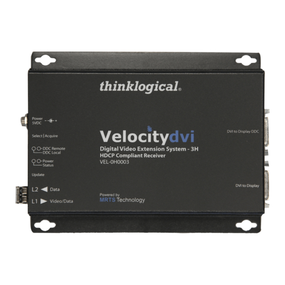
- Page 32 3.2.1. VelocityDVI HDCP Compliant Fiber Optic Extenders Velocity-3H HDCP Compliant VEL-0H0003-LCTX-RX TRANSMITTER ® ® Power 5VDC Velocitydvi DVI to Local Select | Acquire Display DDC Remote DDC Local Digital Video Extension System – 3H Power Status HDCP Compliant Transmitter Update | HID L1 ◄...
- Page 33 Velocity-3AH Audio/HDCP Compliant VEL-AH0003-LCTX-RX TRANSMITTER Line IN Serial ® ® Mic OUT Power 5VDC Velocitydvi Select | Acquire DVI to Local Display DDC Remote DDC Local Digital Video Extension System – 3AH Power Status HDCP Compliant Transmitter VEL-AH0003-LCTX Update | HID L1 ◄...
- Page 34 Velocity-3NH Network/HDCP Compliant VEL-NH0003-LCTX-RX TRANSMITTER Line IN Network ® ® Mic OUT 100/10 | FD/COL Power 5VDC Velocitydvi Select | Acquire DVI to Local Display DDC Remote DDC Local Digital Video Extension System – 3NH Power Status HDCP Compliant Transmitter VEL-NH0003-LCTX Update | HID L1 ◄...
-
Page 35: Table Of Velocitydvi Chassis Dimensions
3.2.2. Velocitydvi-33 and -63 Transmitter and Receiver Back Panels Velocitydvi-33 Transmitter Receiver Velocitydvi-63 Transmitter Receiver 3.2.3. Table of VelocityDVI Chassis Dimensions VelocityDVI Model DIMENSIONS (inches) DIMENSIONS (metric) VEL-3 5.375"W x 7.0"D x 1.1"H 136.65mm x 177.80mm x 27.94mm VEL-3 with Neutrik 5.375"W x 7.0"D x 2.0"H... -
Page 36: Ddc (Display Data Channel ) And Edid (Extended Display Identification Data )
4. DDC and EDID (Display Data Channel) is a VESA standard transport medium between a CPU’s graphics adapter and monitor. The DDC is used to pass EDID (Extended Display Identification Data), which is stored in the monitor and describes its characteristics (vendor name, serial number, frequency range, etc.). With this information the CPU and video card can determine what resolutions the monitor is capable of. -
Page 37: Load Default Edid Table
Local Static mode operates in the same manner as Remote Static mode except that the EDID table is read from a monitor plugged into the local port of the TX. Once the ACQUIRE button is pressed the TX will begin reading the DDC from the locally connected monitor until a valid EDID table is read. The table will then be stored on the TX and presented to the CPU. -
Page 38: Ddc Leds And Mode Button Operation
4.2.1 DDC LEDs and Mode Button Operation • Acquire Button The upper button is the Acquire Button. This button is used to initiate DDC collection. This button works with all modes except Pass-Thru. • Select Button The lower button is used to select the DDC Mode of operation. The modes will cycle through Remote Dynamic, Remote Static, PassThru and Local Static. -
Page 39: Regulatory And Safety Compliance
5.2. Regulatory Compliance Thinklogical VelocityDVI Extender products are designed and made in the USA. VelocityDVI Extender products have been tested by a nationally recognized testing laboratory and found to be compliant with the following standards (both domestic USA and many international locations). -
Page 40: Australia & New Zealand
5.2.2. Australia & New Zealand This is a Class A product. In a domestic environment this product may cause radio interference, in which case the user may be required to take corrective measures. 5.2.3. European Union 5.2.3.1. Declaration of Conformity Product name VelocityDVI Digital Video Extension System-3, VelocityDVI Digital Video Extension System-6, VelocityDVI Digital Video Extension System-33, VelocityDVI Digital Video Extension System-63... -
Page 41: Product Serial Number
Please use one of the following email addresses: info@thinklogical.com – Information on Thinklogical and our products. ® sales@thinklogical.com – Sales Department - orders, questions or issues. support@thinklogical.com – Product support, technical issues or questions, product repairs and request for Return Authorization. Page 39 2 0 1 3 V e l o c i t y D V I E x t e n d e r P r o d u c t M a n u a l , R e v . -
Page 42: Telephone
If you wish to return your device, contact the Thinklogical authorized dealer where you purchased the ® device, or if you purchased directly, call Thinklogical at 1-800-291-3211 (USA). Page 40 2 0 1 3 V e l o c i t y D V I E x t e n d e r P r o d u c t M a n u a l , R e v . A , J u n e ,... -
Page 43: Return Merchandise Authorization
Return Authorization If you have any issue with any Thinklogical product, have product questions or need technical assistance with your Thinklogical system, please contact Customer Support at 1-800-291-3211 (USA only) or 1- 203-647-8700 and let us help. If you must return a product to Thinklogical directly, Customer Support will ask you to describe the ®... -
Page 44: Appendix A: Installation Overview
Appendix A: Installation Overview A.1. VEL-3 Velocitydvi Digital Video Extender-3 Installation Overview STEP 4: Connect the supplied AC Power Adapter (PWR-000022-R) to the Tx and Power Supply plug it into a standard AC source. (PWR-000022-R) Local Monitor STEP 5: Connect the video source (CPU) to the Tx with a DVI-D M-M Transmitter VEL-000M03-LCTX Cable. -
Page 45: Vel-3 A/V
A.2. VEL- 3 A/V+ Page 43 2 0 1 3 V e l o c i t y D V I E x t e n d e r P r o d u c t M a n u a l , R e v . A , J u n e ,... -
Page 46: Vel-6
A.3. VEL-6 Velocitydvi Digital Video Extender-6 Dual-Link Installation Overview STEP 4: Connect the supplied AC Power Adapter (PWR-000022-R) to the Tx and Power Supply plug it into a standard AC source. (PWR-000022-R) Local Monitor STEP 5: Connect the video source Transmitter VEL-000M06-LCTX (CPU) to the Tx with a DVI-D M-M Cable. -
Page 47: Vel-6 A/V
A.4. VEL-6 A/V+ Velocitydvi Digital Video Extender-6AV+ Installation Overview STEP 4: Connect the supplied AC Power Adapter (PWR-000022-R) to the Tx and Power Supply plug it into a standard AC source. (PWR-000022-R) RJ45 to Local Monitor Transmitter VEL-AV0M06-LCTX STEP 5: Connect the video source (CPU) to the Tx with a DVI-D M-M Cable. -
Page 48: Vel-33
Copyright 2013. All rights reserved. Printed in the U.S.A. All trademarks and service marks are the property of their respective owners. STEP 6: Using the supplied DVI-D male to male cables, connect the video output sources to the Transmitter Unit’s DVI IN receptacles. -
Page 49: Vel-63
A.6 VEL-63 Page 47 2 0 1 3 V e l o c i t y D V I E x t e n d e r P r o d u c t M a n u a l , R e v . A , J u n e ,... -
Page 50: Appendix B: Dvi Extender Mounting
Users may choose the most appropriate fasteners and anchors to mount each unit according to the requirements of each application. VelocityDVI-33 and -63 chassis can be desk-top (feet provided) or standard EIA 19” rack-mounted. -
Page 51: Appendix C: Rj45 Adapter Pin - Outs
Appendix C: RJ-45 Adapter Pin-outs Page 49 2 0 1 3 V e l o c i t y D V I E x t e n d e r P r o d u c t M a n u a l , R e v . A , J u n e ,... -
Page 52: Appendix D: Automatic Fail-Over Option
Appendix D: Automatic Fail-Over Option For applications that require an automatic fail-over system, Thinklogical offers a solution. The ® Automatic Fail-Over Option features a transmitter with two separate fiber paths and the option to select which of the two is the viable path. -
Page 53: Appendix E: Velocity System -3/6 Enhanced Status Led Information
Appendix E: Velocity System-3 and System-6 Enhanced Status LED Information* VelocityDVI Systems VelocityDVI Systems Velocity HDCP Compliant Systems Velocity HDCP Compliant Systems STATUS LED STATUS LED *Applies to modules shipped after March, 2013. Velocity System-3 TX STATUS LED DDC MODE DVI SOURCE L2 ACTIVE STATUS LED... - Page 54 Velocity System-3 TX REDUNDANT STATUS LED DDC MODE DVI SOURCE L2 ACTIVE L2’ ACTIVE STATUS LED NEW ENHANCEMENT RED FLASH NOT LOCAL STATIC GREEN FLASH DON’T CARE DON’T CARE ORANGE FLASH DON’T CARE GREEN LOCAL STATIC ORANGE DON’T CARE DON’T CARE DON’T CARE RED FLASH Velocity System-3 RX REDUNDANT STATUS LED...
- Page 55 Velocity System-3 HDCP Compliant TX STATUS LED DDC MODE DVI SOURCE L2 ACTIVE STATUS LED NEW ENHANCEMENT RED FLASH NOT LOCAL STATIC GREEN DON’T CARE ORANGE LOCAL STATIC RED FLASH DON’T CARE DON’T CARE Velocity System-3 HDCP Compliant RX STATUS LED MONITOR L1 ACTIVE STATUS LED...
Need help?
Do you have a question about the VelocityDVI-33 and is the answer not in the manual?
Questions and answers