Regulus CSE2 MIX F W 1F Installation And Operation Manual
Pump station
Hide thumbs
Also See for CSE2 MIX F W 1F:
- Installation and operation manual (24 pages) ,
- Installation and operation manual (22 pages) ,
- Installation and operation manual (16 pages)

Related Manuals for Regulus CSE2 MIX F W 1F


Summary of Contents for Regulus CSE2 MIX F W 1F
- Page 1 Installation and Operation Manual CSE2 MIX F W 1F PUMP STATION CSE2 MIX F W 1F...
-
Page 2: Table Of Contents
AVC ACTUATOR FOR MIXING VALVE ......... 3.3. LK 840 MIXING VALVE ..............3.4. CHECK VALVE ................3.5. FILTER WITH MAGNET ..............3.6. BALL VALVES ................PUMP STATION INSTALLATION ............. TEMPERATURE SENSOR INSTALLATION ..........OPTIONAL ACCESSORIES ..............Regulus CSE2 MIX F W 1F - www.regulus.eu │... -
Page 3: Introduction
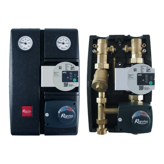
INTRODUCTION CSE2 MIX F W 1F twin-line pump station is designed for mixed heating circuits. It provides flow through the heating system, mixes to the outlet temperature using a motorized mixing valve (controlled by an external controller). The pump station includes a filter with magnet, so it is also suitable for older steel pipe systems. -
Page 4: Pump Station Components
6 – Dirt filter with magnet 7 – Lever for ball valves 8 – Ball valve w. sheath for temperature sensor (heating circuit outlet) 9 – Ball valve w. sheath for temperature sensor (heating circuit inlet) Regulus CSE2 MIX F W 1F - www.regulus.eu │... -
Page 5: Wilo Para 25/8 Sc Pump
2 - electric short circuit in pump 3 - pump overheated 1 - unforced fluid circulation through the pump FLASHING RED AND GREEN 2 - pump speed lower than desired 3 - air in pump Regulus CSE2 MIX F W 1F - www.regulus.eu │... - Page 6 To return to the factory settings, press and hold the operating button for at least 4 seconds (all LEDs flash for 1 second) and turn off the pump by unplugging. When switched on again, the pump will run at the factory settings. Regulus CSE2 MIX F W 1F - www.regulus.eu │...
- Page 7 / n=const and the respective performance curve). LED indicators Operating mode Performance curve constant speed constant speed Δp-v variable Δp-v variable Δp-v variable Δp-c constant Δp-c constant Δp-c constant constant speed Regulus CSE2 MIX F W 1F - www.regulus.eu │...
- Page 8 HW storage tank heating) and for single- line heating systems with radiators. The pump maintains a constant set delivery head regardless of pumping capacity. Q [m³/ h] max. P [W] Q [m³/ h] Regulus CSE2 MIX F W 1F - www.regulus.eu │...
-
Page 9: Avc Actuator For Mixing Valve
Max. power input 2.5 VA IP rating IP42 Protection class II by EN 60730-1 Ambient temperature 0 - 40 °C Cable (cross section - length) 3 x 0.5 mm² - 2 m Regulus CSE2 MIX F W 1F - www.regulus.eu │... -
Page 10: Lk 840 Mixing Valve
< 1 % Kv at 5 m H O pressure difference Connections 3 x G 1“ M Materials Valve housing, spindle and member brass Gasket EPDM Mixing Valve Pressure Drop Diagram Regulus CSE2 MIX F W 1F - www.regulus.eu │... -
Page 11: Check Valve
Dirt trapped on the magnet must be wiped off and then reassembled by inserting the strainer, screwing in and tightening the cap. Filter w. Magnet Pressure Drop Diagram Regulus CSE2 MIX F W 1F - www.regulus.eu │... -
Page 12: Ball Valves
As a result, unintentional closure of the system by an unauthorized person is not possible. OPEN CLOSED groove in the flow direction groove perpendicular to the flow direction Regulus CSE2 MIX F W 1F - www.regulus.eu │... -
Page 13: Pump Station Installation
The package includes a mounting kit that is used to fix the pump station to the intended place. The mounting kit includes: Screw 5x50, round head 2 pcs 6.4 stainless steel washer, DIN 9021/A2 2 pcs Wall plug 8mm TX 2 pcs Regulus CSE2 MIX F W 1F - www.regulus.eu │... -
Page 14: Temperature Sensor Installation
Temperature sensor placement Securing the temperature sensor with the screw Running the sensor cable through the recess in the insulation Regulus CSE2 MIX F W 1F - www.regulus.eu │... -
Page 15: Optional Accessories
G 1“ Fu x G 1“ F x G 1/2“ M with manifold connection fittings Code 17928 – G 1“ Fu x G 5/4“ F manifold connection fittings Code 17920 code 17928 Regulus CSE2 MIX F W 1F - www.regulus.eu │... - Page 16 Fit the plastic adapter on the shaft. The flat edge of the shaft and the arrow on the plastic adapter are located on the same side as the valve arrow on member. plastic adapter Regulus CSE2 MIX F W 1F - www.regulus.eu │...
- Page 17 2 is closed). Having performed the check, tighten the fastening screw and switch back to automatic control. The actuator shall be installed in the same manner as in the figure. Regulus CSE2 MIX F W 1F - www.regulus.eu │...
- Page 18 ©2020 We reserve the right to errors, changes and improvements without prior notice. REGULUS spol. s r.o. E-mail: sales@regulus.eu Web: www.regulus.eu...
Need help?
Do you have a question about the CSE2 MIX F W 1F and is the answer not in the manual?
Questions and answers