
Subscribe to Our Youtube Channel
Related Manuals for Pepperl+Fuchs PMI360DV-F130-IU2E0-V15


Summary of Contents for Pepperl+Fuchs PMI360DV-F130-IU2E0-V15
- Page 1 FACTORY AUTOMATION MANUAL PMI360DV-F130-IU2E0-V15 Inductive Angle Positioning System...
- Page 2 PMI360DV-F130-IU2E0-V15 With regard to the supply of products, the current issue of the following document is ap- plicable: The General Terms of Delivery for Products and Services of the Electrical Indus- try, published by the Central Association of the Electrical Industry (Zentralverband Elektrotechnik und Elektroindustrie (ZVEI) e.V.) in its most recent version as well as the...
-
Page 3: Table Of Contents
PMI360DV-F130-IU2E0-V15 Introduction................. 5 Declaration of Conformity............6 Safety ................... 7 Symbols Used ..................7 Intended Use ..................7 General Safety Instructions ..............7 Product Description ..............8 Use and Application................8 Displays and Controls ................. 9 Accessories ..................9 4.3.1 Connection Cables ................ - Page 4 PMI360DV-F130-IU2E0-V15 Troubleshooting................ 22 Faults when Programming the Outputs ...........22 Faults During Operation..............22 10 Disposal..................24...
-
Page 5: Introduction
PMI360DV-F130-IU2E0-V15 Introduction Introduction Congratulations You have chosen a device manufactured by Pepperl+Fuchs. Pepperl+Fuchs develops, produces and distributes electronic sensors and interface modules for the market of automation technology on a worldwide scale. Symbols used The following symbols are used in this manual: Note! This symbol draws your attention to important information. -
Page 6: Declaration Of Conformity
This product was developed and manufactured under observance of the applicable European standards and guidelines. Note! A Declaration of Conformity can be requested from the manufacturer. The product manufacturer, Pepperl+Fuchs GmbH, D-68307 Mannheim, has a certified quality assurance system that conforms to ISO 9001. ISO9001... -
Page 7: Safety
User modification and or repair are dangerous and will void the warranty and exclude the manufacturer from any liability. If serious faults occur, stop using the device. Secure the device against inadvertent operation. In the event of repairs, return the device to your local Pepperl+Fuchs representative or sales office. Note! Disposal Electronic waste is hazardous waste. -
Page 8: Product Description
The PMI360DV-F130-IU2E0-V15 has an analog output for the analog indication of angular positions. For high resistance loads (>3.3 kΩ), the angular position is output as a voltage value 0 ... -
Page 9: Displays And Controls
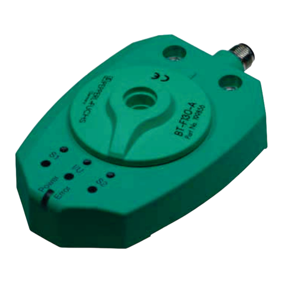
LED indicators Programming buttons 4 LEDs and 3 programming buttons are located on top of the PMI360DV-F130-IU2E0-V15. The central, front "Power/Error" LED is a 2-color LED that lights up or flashes green (normal operation) or red (fault) depending on the operating state of the device. The LEDs "S1", "S2"... -
Page 10: Actuator
PMI360DV-F130-IU2E0-V15 Product Description M12 x 1 single-ended female cordsets, 5-pin Illustration Material Length Model number M12 x 1, straight, 5-pin V15-G-2M-PVC V15-G-5M-PVC 10 m V15-G-10M-PVC V15-G-2M-PUR V15-G-5M-PUR 10 m V15-G-10M-PUR M12 x 1, angled, 5-pin V15-W-2M-PVC V15-W-5M-PVC 10 m V15-W-10M-PVC... -
Page 11: Installation
PMI360DV-F130-IU2E0-V15 Installation Installation Note on Safety Warning! Risk of short circuit Working on live parts can cause injuries and can compromise the function and the electrical safety of the device. Before working on the device, always disconnect the supply voltage. - Page 12 PMI360DV-F130-IU2E0-V15 Installation Dimensions when using a different actuating element Drive shaft Insulation ring made from non-conductive material Separate actuator (L ≥23 µµ) Sensitive surface on the sensor (black, cylindrical inner surface) Sensor Insert the shaft until actuator C and the sensitive surface on sensor D overlap as far as possible.
-
Page 13: Electrical Connection
4. Check that the wires are connected correctly before connecting the cordset to the sensor. On Pepperl+Fuchs cordsets, the wire colors are assigned to the connecting pins in the connector according to DIN EN 60947-5-2. 5. Attach the socket on the cordset to the connector on the sensor and tighten the union nut by hand. -
Page 14: Commissioning
PMI360DV-F130-IU2E0-V15 Commissioning Commissioning Programming the Switching Outputs 2 switching windows with a window width of 5° (+/- 2.5°) are preset at the factory. The switching windows lie between the angle settings 117.5°... 122.5° (S1), and 237.5° ... 242.5° (S2). You can modify the position and width of these switching windows by programming them accordingly. - Page 15 PMI360DV-F130-IU2E0-V15 Commissioning Program switching output 1 (S1) as follows: Programming switching output S1 1. Make sure that the sensor is mounted correctly and securely, and check that an actuator with the specified dimensions is positioned at the correct distance from the surface of the sensor.
-
Page 16: Programming The Analog Output
PMI360DV-F130-IU2E0-V15 Commissioning Note! If interrupted for more than 1 minute, the programming process is terminated. The sensor continues operating with unchanged values. Note! If any other button is actuated, the programming process is terminated. The sensor continues operating with unchanged values. - Page 17 PMI360DV-F130-IU2E0-V15 Commissioning Program the analog output as follows: Programming the analog output 1. Make sure that the sensor is mounted correctly and securely, and check that an actuator with the specified dimensions is positioned at the correct distance from the surface of the sensor.
- Page 18 PMI360DV-F130-IU2E0-V15 Commissioning Note! Programming an angle segment of exactly 360° If you intend to program an angle segment of exactly 360° for the analog output, you can make use of the restriction that prevents the angle segment from exceeding 360°.
-
Page 19: Output Function In Normal Operation
PMI360DV-F130-IU2E0-V15 Output Function in Normal Operation Output Function in Normal Operation Example I/U2 I/U1 0° 90° 180° 270° 360° 20° 60° I/U2 I/U1 Figure 7.1 Output function depends on the position of the actuator and the method used to program the outputs. -
Page 20: Function Of Switching Outputs S1 And S2
PMI360DV-F130-IU2E0-V15 Output Function in Normal Operation 8. Angular range outside of analog measurement range. The function of the analog output depends on whether the output assumes the function of a voltage or a current output (de- pending on the load). - Page 21 PMI360DV-F130-IU2E0-V15 Output Function in Normal Operation The analog output shows the minimum value of the relevant value range (4 mA or 0 V) at the start position (I/U1). If the actuator rotates toward the programmed end position (I/U2), the output value increases proportionally in relation to the rotation angle covered. When the programmed end position (I/U2) is reached, the analog output shows its maximum value (20 mA or 10 V).
-
Page 22: Maintenance And Repair
PMI360DV-F130-IU2E0-V15 Maintenance and Repair Maintenance and Repair Maintenance The sensor's transmission properties are stable over long periods. For this reason, regular adjustments to, and maintenance on the sensor itself, are not necessary. Nevertheless check in the course of normal maintenance intervals that the sensor, the actuator and the connector are securely attached. - Page 23 PMI360DV-F130-IU2E0-V15 Troubleshooting Troubleshooting Faults When Programming the Outputs If unexpected statuses occur when programming the outputs of the inductive angular positioning system, refer to the table below for possible causes and instructions for rectifying the problem. Status Possible cause Action...
- Page 24 PMI360DV-F130-IU2E0-V15 Troubleshooting Faults During Operation If the inductive angular positioning system does not function correctly, refer to the table below for possible causes and instructions for rectifying the problem. Error Possible cause Action "Power/Error" LED does not The power supply is switched...
- Page 25 PMI360DV-F130-IU2E0-V15 Disposal Disposal Electronic waste is hazardous waste. When disposing of the equipment, observe the current statutory requirements in the respective country of use, as well as local regulations. The device does not contain any batteries that require separate disposal.
- Page 26 Twinsburg, Ohio 44087 · USA Tel. +1 330 4253555 E-mail: sales@us.pepperl-fuchs.com Asia Pacific Headquarters Pepperl+Fuchs Pte Ltd. Company Registration No. 199003130E Singapore 139942 Tel. +65 67799091 E-mail: sales@sg.pepperl-fuchs.com www.pepperl-fuchs.com Subject to modifications / DOCT-4795A Copyright PEPPERL+FUCHS • Printed in Germany 02/2019...
Need help?
Do you have a question about the PMI360DV-F130-IU2E0-V15 and is the answer not in the manual?
Questions and answers