Sign In
Upload
Download
Table of Contents
Contents
Add to my manuals
Delete from my manuals
Share
URL of this page:
HTML Link:
Bookmark this page
Add
Manual will be automatically added to "My Manuals"
Print this page
×
Bookmark added
×
Added to my manuals
Manuals
Brands
Pepperl+Fuchs Manuals
Measuring Instruments
PMI Series
Manual
Pepperl+Fuchs PMI Series Manual
Position measurement system with io-link
Hide thumbs
1
2
Table Of Contents
3
4
5
6
7
8
9
10
11
12
13
14
15
16
17
18
19
20
21
22
23
24
25
26
27
28
29
30
31
32
33
34
35
36
37
38
39
40
41
42
43
44
45
46
47
48
page
of
48
Go
/
48
Contents
Table of Contents
Troubleshooting
Bookmarks
Table of Contents
Table of Contents
1 Introduction
Content of this Document
Target Group, Personnel
Symbols Used
Intended Use
General Safety Instructions
Declaration of Conformity
2 Product Description
Use and Application
LED Indicators
Accessories
Damping Element
Parameterization Aids
M12 Connection Cable, 5-Pin
3 Installation
Safety Information
Definition of the Measuring Range/Position
Preparation
Mounting
Connection
4 Commissioning
Commissioning Without IO-Link
Commissioning with IO-Link to a Controller
Commissioning with IO-Link Using Pactware and IODD
Commissioning with IO-Link in an FDT Environment
5 IO-Link Parameterization
Overview
Identification Menu Item
Parameter Menu Item
Observation Menu Item
Diagnosis Menu Item
Process Data Menu Item
Process Data Structure Menu Item
Events Menu Item
Info Menu Item
Connection Info Menu Item
6 Switchpoint Mode
7 Error Behaviour
Process Data, Position Value
Analog Output Error Behavior
8 Maintenance and Repair
Maintenance
Resetting the Output Functions to the Factory Default
9 Troubleshooting
What to Do in Case of a Fault
10 Appendix
Process Data Structure
Telegram Types
IO-Link Communication and ID Parameters
IO-Link Standard Parameters
IO-Link Device Parameters
Error Codes
Event Data
Advertisement
Quick Links
1
Definition of the Measuring Range/Position
Download this manual
FACTORY AUTOMATION
MANUAL
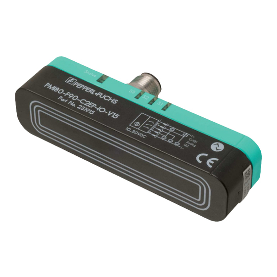
PMIxxx-F90-...-IO-...
Inductive
Position Measurement System
with IO-Link
Table of
Contents
Previous
Page
Next
Page
1
2
3
4
5
Advertisement
Table of Contents
Need help?
Do you have a question about the PMI Series and is the answer not in the manual?
Ask a question
Questions and answers
Related Manuals for Pepperl+Fuchs PMI Series
Measuring Instruments Pepperl+Fuchs PMI360DV-F130-IU2E2-V15 Manual
Inductive angle positioning system (24 pages)
Measuring Instruments Pepperl+Fuchs PMI120-F90 Series Manual
Position measurement system with io-link (48 pages)
Measuring Instruments Pepperl+Fuchs PMI360DV-F130-IU-V15 Manual
Inductive angle positioning system (22 pages)
Measuring Instruments Pepperl+Fuchs PMI360D-F130-IE8-V15 Manual
Inductive position measuring system (20 pages)
Measuring Instruments Pepperl+Fuchs PCV100-F200-B17-V1D-6011 Manual
Data matrix positioning system for tia portal (20 pages)
Measuring Instruments Pepperl+Fuchs PMI360D-F130-IE8-V15-Y205400 Quick Start Manual
Ind. angular measuring system (2 pages)
Measuring Instruments Pepperl+Fuchs PMI360DV-F130-IU2E0-V15 Manual
Inductive angle positioning system (26 pages)
Measuring Instruments Pepperl+Fuchs Pulscon LTC50 Technical Information
Guided level radar (92 pages)
Measuring Instruments Pepperl+Fuchs Pulscon LTC50 HART Manual
Guided level radar (184 pages)
Measuring Instruments Pepperl+Fuchs PMI15V-F166 IO Series Manual
Parameterizing inductive position measurement systems with io-link interface (32 pages)
Measuring Instruments Pepperl+Fuchs LGM Series Manual
Measuring automation light grid (90 pages)
Measuring Instruments Pepperl+Fuchs AS-i Manual
Speed monitor (38 pages)
Measuring Instruments Pepperl+Fuchs IMU360D-F99-B20 Manual
F99 fusion inertial measurement unit with can sae j1939 protocol (33 pages)
Measuring Instruments Pepperl+Fuchs VAS-2A1L-K31 Manual
As-interface safety monitor (108 pages)
Measuring Instruments Pepperl+Fuchs HART LUC-M Series Operating Instructions Manual
Ultrasonic level sensor (64 pages)
Measuring Instruments Pepperl+Fuchs Pulscon LTC57 Manual
Profibus pa guided level radar level measurement in bulk solids (176 pages)
This manual is also suitable for:
Pmi40-f90 series
Pmi80-f90 series
Pmi120-f90 series
Pmi80-f90-iu2ep-io-v15
Table of Contents
Print
Rename the bookmark
Delete bookmark?
Delete from my manuals?
Login
Sign In
OR
Sign in with Facebook
Sign in with Google
Upload manual
Upload from disk
Upload from URL


Need help?
Do you have a question about the PMI Series and is the answer not in the manual?
Questions and answers