
Related Manuals for Pepperl+Fuchs Pulscon LTC50 HART


Summary of Contents for Pepperl+Fuchs Pulscon LTC50 HART
- Page 1 PROCESS AUTOMATION MANUAL Pulscon LTC50 HART Guided Level Radar Level measurement in liquids ISO9001...
- Page 2 Pulscon LTC50 HART With regard to the supply of products, the current issue of the following document is applicable: The General Terms of Delivery for Products and Services of the Electrical Industry, published by the Central Association of the Electrical Industry (Zentralverband Elektrotechnik und Elektroindustrie (ZVEI) e.V.) in its most recent version as well as the supplementary clause:...
-
Page 3: Table Of Contents
Pulscon LTC50 HART Content Important document information ........6 Document function . - Page 4 Pulscon LTC50 HART Content Operation options ..........60 Overview.
- Page 5 Pulscon LTC50 HART Content 13 Repairs ............97 13.1 General information on repairs .
-
Page 6: Important Document Information
Pulscon LTC50 HART Important document information Important document information Document function These Operating Instructions contain all the information that is required in various phases of the life cycle of the device: from product identification, incoming acceptance and storage, to mounting, connection, operation and commissioning through to troubleshooting, maintenance and disposal. - Page 7 Pulscon LTC50 HART Important document information 1.2.2 Electrical symbols Symbol Meaning Direct current A terminal to which DC voltage is applied or through which direct current flows. Alternating current A terminal to which alternating voltage is applied or through which alternating current flows.
- Page 8 Pulscon LTC50 HART Important document information 1.2.4 Symbols for certain types of information Symbol Meaning Allowed Indicates procedures, processes or actions that are allowed. Preferred Indicates procedures, processes or actions that are preferred. Forbidden Indicates procedures, processes or actions that are forbidden.
-
Page 9: Supplementary Documentation
Pulscon LTC50 HART Important document information Supplementary documentation Document Purpose and content of the document Technical Information Planning aid for your device TI01000O (LTC50) The document contains all the technical data on the device and provides an overview of the accessories and other products that can be ordered for the device. - Page 10 Pulscon LTC50 HART Important document information Feature Approval Feature "Electrical output" "Approval" Option IH Option ID Option IE Option PA Option AH Option DH CSA C/US IS Cl.I Div.1 SI00530O SI00530O SI00530O SI00571O SI00530O Gr.A-D CSA C/US XP Cl.I Div.1...
-
Page 11: Basic Safety Instructions
The manufacturer is not liable for damage caused by improper or non-designated use. Verification for borderline cases: • For special measured materials and cleaning agents, Pepperl+Fuchs is glad to provide assistance in verifying the corrosion resistance of wetted materials, but does not accept... -
Page 12: Workplace Safety
It meets general safety standards and legal requirements. It also complies with the EC directives listed in the device-specific EC Declaration of Conformity. Pepperl+Fuchs confirms this by affixing the CE mark to the device. -
Page 13: Product Description
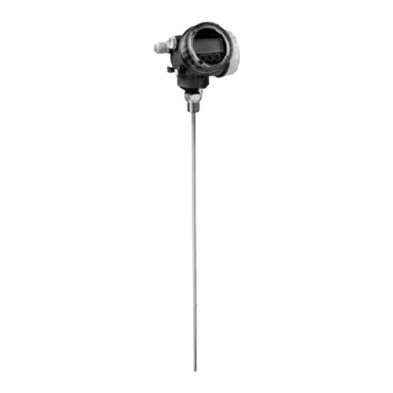
Pulscon LTC50 HART Product description Product description Design 3.1.1 Device Figure 3.1 Design Electronics housing Process connection (thread) Rope probe End-of-probe weight Rod probe... - Page 14 Pulscon LTC50 HART Product description 3.1.2 Electronics housing Figure 3.2 Design of the electronics housing Electronics compartment cover Display module Main electronics module Cable glands (1 or 2, depending on instrument version) Nameplate I/O electronics module Terminals (pluggable spring terminals)
-
Page 15: Registered Trademarks
Pulscon LTC50 HART Product description Registered trademarks HART ® • Registered trademark of the HART Communication Foundation, Austin, USA PROFIBUS ® • Registered trademark of the PROFIBUS User Organization, Karlsruhe, Germany KALREZ , VITON ® ® • Registered trademark of DuPont Performance Elastomers L.L.C., Wilmington, USA TEFLON ®... -
Page 16: Incoming Acceptance And Product Identification
Made in Germany note? DELIVERY NOTE Is the DVD (operating tool) present? If required (see nameplate): Are the Safety Instructions (SI) present? Table 4.1 Note! If one of the conditions does not comply, contact your Pepperl+Fuchs distributor. -
Page 17: Product Identification
Pulscon LTC50 HART Incoming acceptance and product identification Product identification The following options are available for identification of the measuring device: • Nameplate specifications • Order code with breakdown of the device features on the delivery note • Scan the 2-D matrix code (QR code) on the nameplate: all the information for the measuring device is displayed. - Page 18 Pulscon LTC50 HART Incoming acceptance and product identification Device ID Material in contact with process Permitted ambient temperature (T Size of the thread of the cable glands Length of probe Signal outputs Operating voltage Note! Only 33 digits of the extended order code can be indicated on the nameplate. If the extended order code exceeds 33 digits, the rest will not be shown.
-
Page 19: Storage, Transport
Pulscon LTC50 HART Storage, Transport Storage, Transport Storage conditions • Permitted storage temperature: -40 ... +80 °C (-40 ... +176 °F) • Use the original packaging. Transport product to the measuring point Warning! Risk of injury! Housing or probe may be damaged or break away. -
Page 20: Mounting
Pulscon LTC50 HART Mounting Mounting Mounting requirements 6.1.1 Suitable mounting position Figure 6.1 Mounting requirements Mounting distances • Distance (A) between wall and rod or rope probe: • for smooth metallic walls: > 50 mm (2 in) • for plastic walls: > 300 mm (12 in) to metallic parts outside the vessel •... - Page 21 Pulscon LTC50 HART Mounting Additional conditions • When mounting in the open, a weather protection cover (1) may be installed to protect the device against extreme weather conditions. • In metallic vessels: Preferably do not mount the probe in the center of the vessel (2), as this would lead to increased interference echoes.
- Page 22 Pulscon LTC50 HART Mounting 6.1.2 Applications with restricted mounting space Mounting with remote sensor The device version with a remote sensor is suited for applications with restricted mounting space. In this case the electronics housing is mounted at a separate position from which it is easier accessible.
- Page 23 Pulscon LTC50 HART Mounting 6.1.3 Notes on the mechanical load of the probe Tensile load limit of rope probes Feature "Probe" Probe Tensile load limit [kN] Option 2, 3 Rope 4 mm (1/6 in) 316 Table 6.1 Bending strength of rod probes Feature "Probe"...
- Page 24 Pulscon LTC50 HART Mounting Bending torque [M] on rod probes, diameter 8 mm (1/3 in) 20.0 18.0 16.0 14.0 12.0 10.0 v = 0.5 m/s v = 0.7 m/s v = 1.0 m/s Probe length [ ] in meters Figure 6.3 6.1.4...
- Page 25 Pulscon LTC50 HART Mounting Nozzle mounting ø ≤150 (6) mm (in) Figure 6.5 • Permissible nozzle diameter: 150 mm (6 in). For larger diameters the near range measuring capability may be reduced. For nozzles DN300: see next section.
- Page 26 Pulscon LTC50 HART Mounting 6.1.5 Securing the probe Securing rope probes Figure 6.7 Sag of the rope: 1 cm per 1 m of the probe length (0.12 in per 1 ft of the probe length) Reliably grounded end of probe...
- Page 27 Pulscon LTC50 HART Mounting Securing rod probes • For Ex-approvals: For probe lengths 3 m (10 ft) a support is required. • In general, rod probes must be supported if there is a horizontal flow (e. g. from an agitator) or in the case of strong vibrations.
- Page 28 Pulscon LTC50 HART Mounting 6.1.6 Special mounting conditions Bypasses and stilling wells Figure 6.9 Mounting in a stilling well Mounting in a bypass Minimum distance between end of probe and lower edge of the bypass; see table below Minimum distance between end of probe and lower edge of the bypass...
- Page 29 Note! With heat insulated tanks the bypass should also be insulated in order to prevent condensate formation. Note! For information on bypass solutions from Pepperl+Fuchs please contact your Pepperl+Fuchs sales representative. Underground tanks Figure 6.10 Use Pulscon LTC51 with a coax probe for nozzles with large diameters in order to avoid...
- Page 30 Pulscon LTC50 HART Mounting Installation at an angle α Figure 6.11 • For mechanical reasons, the probe should be installed as vertically as possible. • With inclined installations the probe length has to be adjusted in dependence to the installation angle.
- Page 31 Pulscon LTC50 HART Mounting Plastic or glass tanks: mounting the probe externally at the wall For plastic and glass tanks, the probe can also be mounted on the outside wall under specific conditions. Figure 6.13 Plastic or glass tank Metal sheet with threaded sleeve...
- Page 32 Pulscon LTC50 HART Mounting Compensation with the gas phase compensation factor The effect of the dielectric wall can be compared to the effect of a dielectric gas phase. Thus it can be compensated for in the same manner. The compensation factor if given by the quotient of the actual probe length LN and the probe length measured when the tank is empty.
- Page 33 Pulscon LTC50 HART Mounting Vessels with heat insulation Note! If process temperatures are high, the device must be included in normal tank insulation to prevent the electronics heating up as a result of heat radiation or convection. The insulation may not exceed beyond the points labeled "MAX" in the drawings.
-
Page 34: Mounting The Device
Pulscon LTC50 HART Mounting Mounting the device 6.2.1 Required mounting tools • For mounting thread 3/4 in: Hexagonal wrench 36 mm • To shorten rod or coax probes: Saw • To shorten rope probes: • Allen key AF3 mm (for 4 mm ropes) or AF4 mm (for 6 mm ropes) •... - Page 35 Pulscon LTC50 HART Mounting Shortening rope probes Rope probes must be shortened if the distance to the container floor or outlet cone is less than 150 mm (6 in). Figure 6.16 Rope material Torque for set screws 4 mm (0.16 in) 40 mm (1.6 in)
- Page 36 Pulscon LTC50 HART Mounting 6.2.3 Mounting the device Mounting devices with thread Figure 6.17 Devices with mounting thread are screwed into a welding boss or a flange and are usually also secured with these. Note! • Tighten with the hexagonal nut only: •...
- Page 37 Pulscon LTC50 HART Mounting Mounting rope probes Warning! Electrostatic discharges may damage the electronics. • Earth the housing before lowering the rope into the vessel. Figure 6.18 When lowering the rope probe into the vessel, observe the following: • Uncoil rope and lower it slowly and carefully into the vessel.
- Page 38 Pulscon LTC50 HART Mounting 6.2.4 Mounting the "Sensor remote" version Note! This section is only valid for devices of the version "Probe design" = "Sensor remote" (feature "Probe design", option B). For the version "Probe design = Sensor remote" the following is supplied: •...
- Page 39 Pulscon LTC50 HART Mounting Connecting the cable Required tools: open-end wrench AF18 6 Nm 6 Nm (4.42 lbf ft) (4.42 lbf ft) = 100 (4) = 100 (4) 6 Nm 6 Nm (4.42 lbf ft) (4.42 lbf ft) Figure 6.20...
- Page 40 Pulscon LTC50 HART Mounting 6.2.5 Turning the transmitter housing To provide easier access to the connection compartment or display module, the transmitter housing can be turned: max.350° 8 mm 8 mm Figure 6.21 Turning the transmitter housing 1. Unscrew the securing screw using an open-ended wrench.
- Page 41 Pulscon LTC50 HART Mounting 6.2.6 Turning the display module 3 mm Figure 6.22 Turning the display module 1. If present: Loosen the screw of the securing clamp of the electronics compartment cover using an Allen key and turn the clamp 90° counterclockwise.
-
Page 42: Post-Installation Check
Pulscon LTC50 HART Mounting Post-installation check • Is the device undamaged (visual inspection)? • Does the device conform to the measuring point specifications? For example: – Process temperature – Process pressure – Ambient temperature range – Measuring range • Are the measuring point identification and labeling correct (visual inspection)? •... -
Page 43: Electrical Connection
Pulscon LTC50 HART Electrical connection Electrical connection Connection conditions 7.1.1 Terminal assignment 2-wire: 4 ... 20 mA HART – – 4 ... 20 mA Figure 7.1 Terminal assignment 2-wire; 4 ... 20 mA HART Active barrier with power supply (e. g. KCD2-STC-Ex1): observe terminal voltage HART communication resistor (... - Page 44 Pulscon LTC50 HART Electrical connection 2-wire: 4 ... 20 mA HART, switch output – ≥ 250 Ω 4 ... 20 mA Figure 7.2 Terminal assignment 2-wire; 4 ... 20 mA HART, switch output Active barrier with power supply (e. g. KCD2-STC-Ex1): observe terminal voltage HART communication resistor (...
- Page 45 Pulscon LTC50 HART Electrical connection 2-wire: 4 ... 20 mA HART, 4 ... 20 mA – 4 ... 20 mA – 4 ... 20 mA Figure 7.3 Terminal assignment 2-wire, 4 ... 20 mA HART, 4 ... 20 mA Connection current output 2 Connection current output 1 Supply voltage for current output 1 (e.
- Page 46 Pulscon LTC50 HART Electrical connection 4-wire: 4 ... 20 mA HART (10.4 ... 48 V DC) 250Ω 4 ... 20 mA Figure 7.4 Terminal assignment 4-wire; 4 ... 20 mA HART (10.4 ... 48 V DC) Evaluation unit, e. g. PLC HART communication resistor (...
- Page 47 Pulscon LTC50 HART Electrical connection Note! In order to ensure electromagnetic compatibility (EMC): Do not only ground the device via the protective earth conductor of the supply cable. Instead, the functional grounding must also be connected to the process connection (flange or threaded connection) or to the external ground terminal.
- Page 48 Pulscon LTC50 HART Electrical connection 4-wire: 4 ... 20 mA HART (90 ... 253 V AC) ≥ 250Ω 4 ... 20 mA Figure 7.5 Terminal assignment 4-wire; 4 ... 20 mA HART (90 ... 253 V AC) Evaluation unit, e. g. PLC HART communication resistor (...
- Page 49 Pulscon LTC50 HART Electrical connection Note! In order to ensure electromagnetic compatibility (EMC): Do not only ground the device via the protective earth conductor of the supply cable. Instead, the functional grounding must also be connected to the process connection (flange or threaded connection) or to the external ground terminal.
- Page 50 Pulscon LTC50 HART Electrical connection Connection examples for the switch output Connection of a relay Connection of a digital input Suitable relays (examples): 1 Pull-up resistor • Solid-state relay: Phoenix Contact OV- 2 Digital input 24DC/480AC/5 with mounting rail connector UMK-1 OM-R/AMS •...
- Page 51 Pulscon LTC50 HART Electrical connection 7.1.2 Cable specification • Minimum cross-section: See the terminal specification in the Technical Information for the device. • For ambient temperature T 60 °C (140 °F): use cable for temperature T + 20 K.
- Page 52 Pulscon LTC50 HART Electrical connection 7.1.3 Device plug connectors Note! For the versions with fieldbus plug connector (M12 or 7/8 in), the signal line can be connected without opening the housing. Pin assignment of the M12 plug connector Meaning Signal +...
- Page 53 Pulscon LTC50 HART Electrical connection 7.1.4 Power supply 2-wire, 4 ... 20 mA HART, passive Approval Terminal voltage U at the Maximum load R, depending on the supply voltage device at the supply unit • Non-Ex 11.5 ... 35 V R [Ω]...
- Page 54 Pulscon LTC50 HART Electrical connection 2-wire; 4 ... 20 mA HART, switch output Approval Terminal voltage U at the Maximum load R, depending on the supply voltage device at the supply unit • Non-Ex 12 ... 35 V R [Ω] •...
- Page 55 Pulscon LTC50 HART Electrical connection 2-wire; 4 ... 20 mA HART, 4 ... 20 mA Approval Terminal voltage U at the Maximum load R, depending on the supply voltage device at the supply unit Channel 1: 13.5 ... 30 V R [Ω]...
- Page 56 Pulscon LTC50 HART Electrical connection 4-wire, 4 ... 20 mA HART, active Electrical Output Terminal voltage U Maximum load R AH: 4-wire 90 ... 253 V AC; 90 ... 253 V AC (50 ... 60 Hz), 500 4 ... 20 mA HART overvoltage category II DH: 4-wire 10.4 ...
-
Page 57: Connecting The Device
Pulscon LTC50 HART Electrical connection Connecting the device Warning! Explosion hazard! • Comply with the relevant national standards. • Observe the specifications in the Safety Instructions (SI). • Only use the specified cable glands. • Check whether the supply voltage matches the specifications on the nameplate. - Page 58 Pulscon LTC50 HART Electrical connection Figure 7.7 7.2.1 Pluggable spring-force terminals Instruments have pluggable spring-force terminals. Rigid conductors or flexible conductors with cable sleeve can directly be inserted and are contacted automatically. To remove cables from the terminal: Press on the groove between the terminals using a flat-tip screwdriver ...
-
Page 59: Post-Connection Check
Pulscon LTC50 HART Electrical connection Post-connection check • Are cables or the device undamaged (visual inspection)? • Do the cables comply with the requirements? • Do the cables have adequate strain relief? • Are all cable glands installed, firmly tightened and correctly sealed? •... -
Page 60: Operation Options
Pulscon LTC50 HART Operation options Operation options Overview 8.1.1 Local operation Order code for "Display, operation", option D Order code for "Display, operation", option E "SD02" "SD03" Operation with push buttons Operation with touch control Table 8.1 8.1.2 Remote operation Via HART protocol Figure 8.1... - Page 61 Pulscon LTC50 HART Operation options Via service interface (CDI) Figure 8.2 Service interface (CDI) of the measuring device (Common Data Interface) Modem Computer with PACTware operating tool...
-
Page 62: Structure And Function Of The Operating Menu
Pulscon LTC50 HART Operation options Structure and function of the operating menu 8.2.1 Structure of the operating menu Menu Submenu/parameter Meaning Language Defines the operating language of the on-site display. Setup Parameter 1 ... Parameter N When all these parameters have been... - Page 63 Pulscon LTC50 HART Operation options 8.2.2 User roles and related access authorization The two user roles Operator and Maintenance have different write access to the parameters if a device-specific access code has been defined. This protects the device configuration via the local display from unauthorized access.
- Page 64 Pulscon LTC50 HART Operation options 8.2.3 Write protection via access code Using the device-specific access code, the parameters for the measuring device configuration are write-protected and their values can no longer be changed via local operation. Define access code via local display 1.
- Page 65 Pulscon LTC50 HART Operation options 8.2.4 Disabling write protection via access code If the symbol appears on the local display in front of a parameter, the parameter is write- protected by a device-specific access code and its value cannot be changed at the moment using the local display.
- Page 66 Pulscon LTC50 HART Operation options 8.2.6 Write protection via lock switch Unlike write protection via device-specific access code, this allows write access to the entire operating menu – other than Contrast display – to be locked. The values of the parameters are still visible, but can no longer be changed (except for Contrast display), either via the local display, CDI interface or bus protocol.
- Page 67 Pulscon LTC50 HART Operation options 8.2.7 Enabling and disabling the keypad lock The keypad lock allows you disable access to the entire operating menu via local operation. Thus navigating through the operating menu or modifying the values of individual parameters is no longer possible.
-
Page 68: Display And Operating Module
Pulscon LTC50 HART Operation options Display and operating module 8.3.1 Display appearance User ABC_ DEFG HIJK LMNO PQRS TUVW Figure 8.5 Appearance of the display and operation module for on-site operation Measured value display (1 value max. size) Header containing tag and error symbol (if an error is active) - Page 69 Pulscon LTC50 HART Operation options Display symbols for the submenus Symbol Meaning Display/operation Is displayed: • in the main menu next to the selection "Display/operation" • in the header, if you are in the "Display/operation" menu Setup Is displayed: • in the main menu next to the selection "Setup"...
- Page 70 Pulscon LTC50 HART Operation options Measured value symbols Symbol Meaning Measured values Level Distance Current output Measured current Terminal voltage Temperature of the electronics or the sensor Measuring channels Measuring channel 1 Measuring channel 2 Status of the measured value Status "Alarm"...
- Page 71 Pulscon LTC50 HART Operation options 8.3.2 Operating elements Meaning Minus key For menu, submenu Moves the selection bar upwards in a picklist. For text and numeric editor In the input mask, moves the selection bar to the left (backwards). Plus key For menu, submenu Moves the selection bar downwards in a picklist.
- Page 72 Pulscon LTC50 HART Operation options 8.3.3 Entering numbers and text Numeric editor Text editor Editing view Display area of the entered values Input mask Operating elements Table 8.9 Input mask The following input symbols are available in the input mask of the numeric and text editor:...
- Page 73 Pulscon LTC50 HART Operation options Text editor Symbol Meaning Selection of letters from A to Z ABC _ … Toggle • between upper-case and lower-case letters • for entering numbers • for entering special characters Confirms selection. Switches to the selection of the correction tools.
- Page 74 Pulscon LTC50 HART Operation options 8.3.4 Opening the context menu Using the context menu, the user can call up the following menus quickly and directly from the operational display: • Setup • Conf. backup disp. • Simulation Calling up and closing the context menu The user is in the operational display.
- Page 75 Pulscon LTC50 HART Operation options 8.3.5 Envelope curve on the display and operating module In order to assess the measuring signal, the envelope curve and – if a mapping has been recorded – the mapping curve can be displayed: (2s)
-
Page 76: Device Integration Via The Hart Protocol
Pulscon LTC50 HART Device integration via the HART protocol Device integration via the HART protocol Overview of the Device Description files (DD) HART Manufacturer ID 17 (0x11) Device type 0x34 HART specification DD files For information and files see: • www.pepperl-fuchs.com •... -
Page 77: Commissioning (Via Operating Menu)
Pulscon LTC50 HART Commissioning (via operating menu) Commissioning (via operating menu) 10.1 Installation and function check Make sure that all final checks have been completed before you start up your measuring point: • Checklist "Post-installation check", see chapter 6 • Checklist "Post-connection check", see chapter 7.2 10.2... -
Page 78: Configuration Of A Level Measurement
Pulscon LTC50 HART Commissioning (via operating menu) 10.3 Configuration of a level measurement 20 mA 100% 4 mA Figure 10.2 Parameters for level measurement with the guided radar Probe length Distance Level Reference point of measurement Empty calibration (= zero) -
Page 79: Recording The Reference Curve
Pulscon LTC50 HART Commissioning (via operating menu) 7. Navigate to: Setup menu Full calibration. Enter distance F between the minimum (0 %) and maximum (100 %) level. 8. Navigate to: Setup menu Level. Displays the measured level L. -
Page 80: Configuration Of The On-Site Display
Pulscon LTC50 HART Commissioning (via operating menu) 10.5 Configuration of the on-site display 10.5.1 Factory settings of the on-site display for level measurements Parameter Factory setting for devices Factory setting for devices with 1 current output with 2 current outputs Format display 1 value, max. -
Page 81: Configuration Of The Current Outputs
Pulscon LTC50 HART Commissioning (via operating menu) 10.6 Configuration of the current outputs 10.6.1 Factory setting of the current outputs for level measurements Current output Allocated measuring 4 mA value 20 mA value value Level linearized 0 % or the... -
Page 82: Configuration Management
Pulscon LTC50 HART Commissioning (via operating menu) 10.7 Configuration management After commissioning, you can save the current device configuration, copy it to another measuring point or restore the previous device configuration. You can do so using the Configuration management parameter and its options. -
Page 83: Protection Of The Settings Against Unauthorized Changes
Pulscon LTC50 HART Commissioning (via operating menu) 10.8 Protection of the settings against unauthorized changes There are two ways to protect the settings against unauthorized changes: • Via parameter settings (software locking), see chapter 8 • Via locking switch (hardware locking), see chapter 8... -
Page 84: Diagnostics And Troubleshooting
Pulscon LTC50 HART Diagnostics and troubleshooting Diagnostics and troubleshooting 11.1 General trouble shooting 11.1.1 General errors Error Possible cause Remedial action Device does not respond. Supply voltage does not match the Connect the correct voltage. value indicated on the nameplate. - Page 85 Pulscon LTC50 HART Diagnostics and troubleshooting 11.1.2 Parametrization errors Error Possible cause Remedial action Measured value wrong If measured distance (Setup menu • Check and adjust the Empty Distance) matches the real calibration parameter if distance: necessary, see page 115.
-
Page 86: Diagnostic Information On Local Display
Pulscon LTC50 HART Diagnostics and troubleshooting 11.2 Diagnostic information on local display 11.2.1 Diagnostic message Faults detected by the self-monitoring system of the measuring device are displayed as a diagnostic message in alternation with the measured value display. Measured value display in alarm condition... - Page 87 Pulscon LTC50 HART Diagnostics and troubleshooting Diagnostics event and event text The fault can be identified using the diagnostics event. The event text helps you by providing information about the fault. In addition, the corresponding symbol is displayed before the diagnostics event.
- Page 88 Pulscon LTC50 HART Diagnostics and troubleshooting Remedial measures X X X X X X X X X X X X X X 20.50 S801 Supply voltage Menu Diagnostic list Diagnostics 1 S801 Supply voltage Diagnostics 2 Diagnostics 3 Supply voltage...
-
Page 89: Diagnostic Event In The Operating Tool
Pulscon LTC50 HART Diagnostics and troubleshooting Calling up remedial measures in diagnostics menu The user is in the Diagnostics menu at an entry for a diagnostics event, e. g. in Diagnostic list submenu or in Previous diagnostics. 1. Press The message for the remedial measures for the selected diagnostic event opens. -
Page 90: Diagnostic List
Pulscon LTC50 HART Diagnostics and troubleshooting 11.4 Diagnostic list In the Diagnostic list submenu, up to 5 currently pending diagnostic messages can be displayed. If more than 5 messages are pending, the messages with the highest priority are shown on the display. - Page 91 Pulscon LTC50 HART Diagnostics and troubleshooting Diagnostic Short text Repairing action Status signal Diagnostic number (from the behavior factory) (from the factory) Module connection Alarm 1. Check module connection 2. Change electronic modules Main electronic failure Change main electronic module...
- Page 92 Pulscon LTC50 HART Diagnostics and troubleshooting Diagnostic Short text Repairing action Status signal Diagnostic number (from the behavior factory) (from the factory) Simulation measured Deactivate simulation Warning value Simulation current Deactivate simulation Warning output 1 to 2 Switch output Deactivate simulation current output...
-
Page 93: Event Logbook
Pulscon LTC50 HART Diagnostics and troubleshooting 11.6 Event logbook 11.6.1 Event history A chronological overview of the event messages that have occurred is provided in the Event list submenu Navigation Diagnostics Event logbook Event list A maximum of 20 event messages can be displayed in chronological order. If the advanced HistoROM function is enabled in the device (order option), up to 100 entries can be displayed. - Page 94 Pulscon LTC50 HART Diagnostics and troubleshooting 11.6.3 List of information events Info number Info name I1000 -------- Device OK I1089 Power on I1090 Configuration reset I1091 Configuration changed I1092 Trend data deleted I1110 Write protection switch changed I1137 Electronic changed...
-
Page 95: Firmware History
Pulscon LTC50 HART Diagnostics and troubleshooting 11.7 Firmware history Date Software Modifications Operating Description of Technical version Instructions Parameters Information 07.2010 01.00.zz Original software • BA01000O/98/EN • GP01000O/98/EN • TI01000O/98/EN/ /05.10 /05.10 05.10 01.2011 01.01.zz • SIL integrated • BA01000O/98/EN •... -
Page 96: Maintenance
Pulscon LTC50 HART Maintenance Maintenance The measuring device requires no special maintenance. 12.1 Exterior cleaning When exterior-cleaning the device, always use cleaning agents that do not attack the surface of the housing and the seals. -
Page 97: Repairs
13.1.1 Repair concept The Pepperl+Fuchs repair concept assumes that the devices have a modular design and that repairs can be done by the Pepperl+Fuchs service or specially trained customers. Spare parts are contained in suitable kits. They contain the related replacement instructions. -
Page 98: Spare Parts
The measuring device must be returned if repairs or a factory calibration are required, or if the wrong measuring device has been ordered or delivered. According to legal regulations, Pepperl+Fuchs, as an ISO-certified company, is required to follow certain procedures when handling returned products that are in contact with medium. -
Page 99: Accessories
Pulscon LTC50 HART Accessories Accessories 14.1 Device-specific accessories 14.1.1 Weather protection cover Accessory Description Weather protection cover mm (in) 298.5(11.8) 298.5(11.8) 273.8(10.8) 273.8(10.8) 164 (6.46) 164 (6.46) 255.1(10) 255.1(10) mm (in) mm (in) a 37.8 mm (1.49 in) b 54 mm (2.13 in) The weather protection cover can be ordered together with the device (product structure, feature "Accessory enclosed", option B "Weather... - Page 100 Pulscon LTC50 HART Accessories 14.1.2 Mounting bracket for the electronics housing Accessory Description Mounting bracket for the electronics housing 122 (4.8) 140 (5.5) 175 (6.9) 158 (6.2) mm (in) A Wall mounting B Pipe mounting For the "Sensor remote" device version, the mounting bracket is part of the delivery.
- Page 101 Pulscon LTC50 HART Accessories Mounting kit, isolated Accessory Description Mounting kit, isolated 1 Insulating sleeve 2 Eye-bolt For reliably insulated fixing of the probe. Maximum process temperature: 150 °C (300 °F) For rope probes 4 mm (1/6 in) or 6 mm (1/4 in) with PA > steel: •...
-
Page 102: Communication-Specific Accessories
Pulscon LTC50 HART Accessories 14.2 Communication-specific accessories Accessory Description HART Loop Converter Evaluates the dynamic HART variables and converts them to KFD2-HLC-Ex1.D.** analog current signals or limit values. Table 14.4 Accessory Description WirelessHART-Adapter Connects field devices to a WirelessHART network. The... -
Page 103: Operating Menu
Pulscon LTC50 HART Operating menu Operating menu 15.1 Overview of the operating menu (for local display) Language page 151 Setup chapter 15.3 Device tag page 113 Distance unit page 113 Tank type page 113 Tube diameter page 114 Medium group... - Page 104 Pulscon LTC50 HART Operating menu Setup Advanced setup Linearization chapter 15.3.4 Linearization type page 127 Unit after linearization page 129 Free text page 129 Maximum value page 130 Diameter page 130 Intermediate height page 131 Table mode page 132...
- Page 105 Pulscon LTC50 HART Operating menu Setup Advanced setup Switch output chapter 15.3.12 Switch output function page 146 Assign status page 147 Assign limit page 147 Assign diagnostic behavior page 147 Switch-on value page 148 Switch-on delay page 149...
- Page 106 Pulscon LTC50 HART Operating menu Diagnostics chapter 15.4 Actual diagnostics page 163 Previous diagnostics page 163 Operating time from restart page 164 Operating time page 164 Diagnostics Diagnostic list chapter 15.4.1 Diagnostics 1 to 5 page 165 Diagnostics Event logbook chapter 15.4.2...
- Page 107 Pulscon LTC50 HART Operating menu Diagnostics Simulation chapter 15.4.6 Assign measurement variable page 173 Value process variable page 173 Simulation current output page 173 Value current output page 174 Switch output simulation page 174 Switch status page 174 Simulation device alarm page 174 Diagnostics ...
-
Page 108: Overview Of The Operating Menu (For Operating Tool)
Pulscon LTC50 HART Operating menu 15.2 Overview of the operating menu (for operating tool) Setup chapter 15.3 Device tag page 113 Distance unit page 113 Tank type page 113 Tube diameter page 114 Medium group page 114 Empty calibration page 115... - Page 109 Pulscon LTC50 HART Operating menu Setup Advanced setup Linearization chapter 15.3.4 Linearization type page 127 Unit after linearization page 129 Free text page 129 Level linearized page 129 Maximum value page 130 Diameter page 130 Intermediate height page 131...
- Page 110 Pulscon LTC50 HART Operating menu Setup Advanced setup Switch output chapter 15.3.12 Switch output function page 146 Assign status page 147 Assign limit page 147 Assign diagnostic behavior page 147 Switch-on value page 148 Switch-on delay page 149...
- Page 111 Pulscon LTC50 HART Operating menu Diagnostics chapter 15.4 Actual diagnostics page 163 Timestamp page 163 Previous diagnostics page 163 Timestamp page 163 Operating time from restart page 164 Operating time page 164 Diagnostics Diagnostic list chapter 15.4.1 Diagnostics 1 to 5...
- Page 112 Pulscon LTC50 HART Operating menu Diagnostics Simulation chapter 15.4.6 Assign measurement variable page 173 Value process variable page 173 Simulation current output page 173 Value current output page 174 Switch output simulation page 174 Switch status page 174 Simulation device alarm page 174 Diagnostics ...
-
Page 113: Setup Menu
Pulscon LTC50 HART Operating menu 15.3 Setup menu Note! Symbols • : Indicates the navigation path to the parameter via display and operating module. • : Indicates the navigation to the parameter via operating tools (e. g. PACTware). • : Marks parameters which can be locked by an access code. See chapter 8. - Page 114 Pulscon LTC50 HART Operating menu Tube diameter Blocking Navigation Setup Tube diameter Prerequisite • Tank type (page 113) = Bypass/pipe • The probe is coated. Description Specify diameter of bypass or stilling well. User entry 0 to 9.999 m Factory setting 0.0384 m...
- Page 115 Pulscon LTC50 HART Operating menu Empty calibration Blocking Navigation Setup Empty calibr. Description Specify the distance E between the process connection and the minimum level (0 %). User entry Depending on the probe Factory setting Depending on the probe Additional information Figure 15.1...
- Page 116 Pulscon LTC50 HART Operating menu Level Navigation Setup Level Description Displays the measured level L (before linearization). Additional information Note: The unit is defined in the Level unit parameter (page 125). Figure 15.3 Level in case of liquid measurements...
- Page 117 Pulscon LTC50 HART Operating menu Signal quality Navigation Setup Signal quality Description Displays the signal quality of the evaluated echo. Display • Strong The evaluated echo exceeds the threshold by at least 10 mV. • Medium The evaluated echo exceeds the threshold by at least 5 mV.
- Page 118 Pulscon LTC50 HART Operating menu Confirm distance Blocking Navigation Setup Confirm distance Description Specify, whether the measured distance matches the real distance. Depending on the selection the device automatically sets the range of mapping. Selection • Manual map • Distance OK •...
- Page 119 Pulscon LTC50 HART Operating menu Present mapping Navigation Setup Present mapping Description Indicates up to which distance a mapping has already been recorded. Mapping end point Blocking Navigation Setup Map. end point Prerequisite Confirm distance (page 118) = Manual map or Distance too small Description Specify new end of the mapping.
- Page 120 Pulscon LTC50 HART Operating menu 15.3.1 Mapping wizard Note! The Mapping wizard is only available when operating via the local display. When operating via an operating tool, all parameters concerning the mapping are located directly in the Setup menu (page 113).
- Page 121 Pulscon LTC50 HART Operating menu 15.3.2 Advanced setup submenu Advanced setup Navigation Setup Advanced setup Locking status Navigation Setup Advanced setup Locking status Description Indicates the write protection with the highest priority that is currently active. User interface •...
- Page 122 • If no key is pressed for 10 min, or the user switches from the navigation and editing mode back to the measured value display mode, the device automatically locks the write protected parameters after another 60 s. Note: Please contact your Pepperl+Fuchs Sales Center if you lose your access code.
- Page 123 Pulscon LTC50 HART Operating menu 15.3.3 Level submenu Level Navigation Setup Advanced setup Level Medium type Navigation Setup Advanced setup Level Medium type Description Specify type of medium. User interface • Liquid • Solid Factory setting •...
- Page 124 Pulscon LTC50 HART Operating menu Process property Blocking Navigation Setup Advanced setup Level Process property Description Specify typical rate of level change. Selection For Medium type = Liquid • Fast > 1m (40 in)/min • Std. < 1 m (40 in)/min •...
- Page 125 Pulscon LTC50 HART Operating menu Advanced process conditions Blocking Navigation Setup Advanced setup Level Adv. conditions Description Specify additional process conditions (if required). Selection • None • Oil/water condensate (only for Medium type = Liquid) • Probe near tank bottom (only for Medium type = Liquid) •...
- Page 126 Pulscon LTC50 HART Operating menu Blocking distance Blocking Navigation Setup Advanced setup Level Blocking dist. Description Specify upper blocking distance UB. User entry 0 to 200 m Factory setting • For coax probes: 0 mm (0 in) •...
- Page 127 Pulscon LTC50 HART Operating menu 15.3.4 Linearization submenu Linearization Navigation Setup Advanced setup Linearization Linearization type Blocking Navigation Setup Advanced setup Linearization Lineariz. type Description Select linearization type. Selection • None • Linear • Table •...
- Page 128 Pulscon LTC50 HART Operating menu • Angled bottom The output value corresponds to the volume or weight in a silo with an angled bottom. The following additional parameters have to be specified: – Unit after linearization (page 129) – Maximum value (page 130): Maximum volume or weight –...
- Page 129 Pulscon LTC50 HART Operating menu Unit after linearization Blocking Navigation Setup Advanced setup Linearization Unit lineariz. Prerequisite Linearization type (page 127) None Description Select unit of the linearized value. Selection SI units US units Imperial units •...
- Page 130 Pulscon LTC50 HART Operating menu Maximum value Blocking Navigation Setup Advanced setup Linearization Maximum value Prerequisite Linearization type (page 127) has one of the following values: • Linear • Pyramid bottom • Conical bottom • Angled bottom •...
- Page 131 Pulscon LTC50 HART Operating menu Intermediate height Blocking Navigation Setup Advanced setup Linearization Intermed. height Prerequisite Linearization type (page 127) has one of the following values: • Pyramid bottom • Conical bottom • Angled bottom Description Specify intermediate height H.
- Page 132 Pulscon LTC50 HART Operating menu Table mode Blocking Navigation Setup Advanced setup Linearization Table mode Prerequisite Linearization type (page 127) = Table Description Select editing mode of the linearization table. Selection • Manual • Semi-automatic • Clear table •...
- Page 133 Pulscon LTC50 HART Operating menu Table number Blocking Navigation Setup Advanced setup Linearization Table number Prerequisite Linearization type (page 127) = Table Description Select table point you are going to enter or change. User entry 1 to 32...
- Page 134 Pulscon LTC50 HART Operating menu Activate table Blocking Navigation Setup Advanced setup Linearization Activate table Prerequisite Linearization type (page 127) = Table Description Activate (enable) or deactivate (disable) the linearization table. Selection • Disable • Enable Factory setting...
- Page 135 Pulscon LTC50 HART Operating menu 15.3.5 Edit table submenu Edit table Note: The Edit table submenu is only available when operating via the local display. When operating via an operating tool, all parameters concerning the table editor are located directly in the Linearization submenu (chapter 15.3.4).
- Page 136 Pulscon LTC50 HART Operating menu 15.3.6 Safety settings submenu Safety settings Navigation Setup Advanced setup Safety sett. Output echo lost Blocking Navigation Setup Advanced setup Safety sett. Output echo lost Description Define the behavior of the output signal in case of a lost echo.
- Page 137 Pulscon LTC50 HART Operating menu Ramp at echo lost Blocking Navigation Setup Advanced setup Safety sett. Ramp echo lost Prerequisite Output echo lost (page 136) = Ramp at echo lost Description Define the slope of the ramp in the case of a lost echo.
- Page 138 Pulscon LTC50 HART Operating menu Blocking distance Blocking Navigation Setup Advanced setup Safety sett. Blocking dist. Description Specify upper blocking distance UB. User entry 0 to 200 m Factory setting • For coax probes: 0 mm (0 in) •...
- Page 139 Pulscon LTC50 HART Operating menu 15.3.7 SIL/WHG confirmation wizard SIL/WHG confirmation Note: Wizard SIL/WHG confirmation wizard is only available for devices with SIL or WHG approval (Feature: "Additional approval", option A: "SIL" or C: "WHG overfill prevention") which are currently not in the SIL- or WHG-locked state.
- Page 140 Pulscon LTC50 HART Operating menu 15.3.9 Probe settings submenu Probe settings The Probe settings submenu helps to ensure that the end of probe signal within the envelope curve is correctly assigned by the evaluation algorithm. The assignment is correct if the length of probe indicated by the device matches the actual length of the probe.
- Page 141 Pulscon LTC50 HART Operating menu Confirm probe length Blocking Navigation Setup Advanced setup Probe settings Confirm length Description Select, whether the value displayed in the Present probe length parameter (page 140) matches the actual length of the probe. Based on this input, the device performs a probe length correction.
- Page 142 Pulscon LTC50 HART Operating menu 15.3.10 Probe length correction wizard Probe length correction Note: The Probe length correction wizard is only available when operating via the local display. When operating via an operating tool, all parameters concerning the probe length correction are located directly in the Probe settings submenu (chapter 15.3.9).
- Page 143 Pulscon LTC50 HART Operating menu 15.3.11 Current output 1 to 2 submenu Current output 1 to 2 Note: The Current output 2 submenu (chapter 15.3.11) is only available for devices with two current outputs. Navigation Setup Advanced setup Curr.output 1 to 2...
- Page 144 Pulscon LTC50 HART Operating menu Current span Blocking Navigation Setup Advanced setup Curr.output 1 to 2 Current span Description Select current range for process variable and alarm signal. Selection • 4...20 mA • 4...20 mA NAMUR • 4...20 mA US •...
- Page 145 Pulscon LTC50 HART Operating menu Failure mode Blocking Navigation Setup Advanced setup Curr.output 1 to 2 Failure mode Prerequisite Current span (page 144) Fixed current Description Select behavior of the output current in case of an error.
- Page 146 Pulscon LTC50 HART Operating menu 15.3.12 Switch output submenu Switch output Navigation Setup Advanced setup Switch output Switch output function Blocking Navigation Setup Advanced setup Switch output Switch out funct Description Select function for switch output.
- Page 147 Pulscon LTC50 HART Operating menu Assign status Blocking Navigation Setup Advanced setup Switch output Assign status Prerequisite Switch output function (page 146) = Digital Output Description Select device status for switch output. Selection • Off • Digital output AD 1 •...
- Page 148 Pulscon LTC50 HART Operating menu Switch-on value Blocking Navigation Setup Advanced setup Switch output Switch-on value Prerequisite Switch output function (page 146) = Limit Description Enter measured value for the switch-on point. User entry Signed floating-point number...
- Page 149 Pulscon LTC50 HART Operating menu Switch-on value < Switch-off value • The output is closed if the measured value is smaller than Switch-on value. • The output is opened if the measured value is larger than Switch-off value. Figure 15.11...
- Page 150 Pulscon LTC50 HART Operating menu Switch-off delay Blocking Navigation Setup Advanced setup Switch output Switch-off delay Prerequisite • Switch output function (page 146) = Limit • Assign limit (page 147) Off Description Define switch-off delay. User entry 0.0 to 100.0 s...
- Page 151 Pulscon LTC50 HART Operating menu 15.3.13 Display submenu Display Note: The Display submenu is only visible if a display module is connected to the device. Navigation Setup Advanced setup Display Language Navigation Setup Advanced setup Display Language Description Set display language.
- Page 152 Pulscon LTC50 HART Operating menu Format display Navigation Setup Advanced setup Display Format display Description Select how measured values are shown on the display. Selection • 1 value, max. size • 1 bargraph + 1 value • 2 values •...
- Page 153 Pulscon LTC50 HART Operating menu Note: • The Value 1 to 4 display parameters (page 153) specify which measured values are shown on the display and in which order. • If more measured values are specified than the current display mode permits, the values alternate on the device display.
- Page 154 Pulscon LTC50 HART Operating menu Display interval Navigation Setup Advanced setup Display Display interval Description Set time measured values are shown on display if display alternates between values. User entry 1 to 10 s Factory setting Additional information The Display interval parameter is only relevant if the number of measured values defined exceeds the number of values the selected display format can display simultaneously.
- Page 155 Pulscon LTC50 HART Operating menu Header text Blocking Navigation Setup Advanced setup Display Header text Prerequisite Header (page 154) = Free text Description Enter display header text. Factory setting ___________________ Additional information The number of characters displayed depends on the characters used.
- Page 156 Pulscon LTC50 HART Operating menu Backlight Navigation Setup Advanced setup Display Backlight Prerequisite The device has the SD03 local display (with optical keys). Description Switch the local display backlight on and off. Selection • Disable • Enable...
- Page 157 Pulscon LTC50 HART Operating menu 15.3.14 Configuration backup display submenu Configuration backup display Note: This submenu is only visible if a display module is connected to the device. The configuration of the device can be saved to the display module at a certain point of time (backup).
- Page 158 Pulscon LTC50 HART Operating menu Configuration management Blocking Navigation Setup Advanced setup Conf.backup disp Config. managem. Description Select action for managing the device data in the display module. Selection • Cancel • Execute backup • Restore • Duplicate •...
- Page 159 Pulscon LTC50 HART Operating menu Backup state Navigation Setup Advanced setup Conf.backup disp Backup state Description Displays which backup action is currently in progress. Comparison result Navigation Setup Advanced setup Conf.backup disp Compar. result Description Displays the comparison result between the device and the display.
- Page 160 Enter access code parameter (page 122). Note: Please contact your Pepperl+Fuchs Sales Center if you lose your access code. Note: For display operation: The new access code is only valid after it has been...
- Page 161 Pulscon LTC50 HART Operating menu Device reset Blocking Navigation Setup Advanced setup Administration Device reset Description Select to which state the device is to be reset. Selection • Cancel • To factory defaults • To delivery settings •...
- Page 162 Pulscon LTC50 HART Operating menu 15.3.16 Define access code wizard Define access code Note: The Define access code wizard is only available when operating via the local display. When operating via an operating tool, the Define access code parameter is located directly in the Administration submenu. The Confirm access code parameter is not available for operation via operating tool.
-
Page 163: Diagnostics Menu
Pulscon LTC50 HART Operating menu 15.4 Diagnostics menu Diagnostics Navigation Diagnostics Actual diagnostics Navigation Diagnostics Actual diagnos. Description Displays current diagnostic message. Additional information The display consists of: • Symbol for event behavior • Code for diagnostic behavior • Operating time of occurrence •... - Page 164 Pulscon LTC50 HART Operating menu Operating time from restart Navigation Diagnostics Time fr. restart Description Displays the time the device has been in operation since the last device restart. User interface Days (d), hours (h), minutes (m), seconds (s)
- Page 165 Pulscon LTC50 HART Operating menu 15.4.1 Diagnostic list submenu Diagnostic list Navigation Diagnostics Diagnostic list Diagnostics 1 to 5 Navigation Diagnostics Diagnostic list Diagnostics 1 Description Display the current diagnostics messages with the highest to fifth-highest priority.
- Page 166 Pulscon LTC50 HART Operating menu 15.4.2 Event logbook submenu Event logbook Note: The Event logbook submenu is only available when operating via the local display. When operating via PACTware, the event list can be displayed in the PACTware function Event List/HistoROM.
- Page 167 Displays serial number of the device. Additional information Note: Uses of the serial number • To identify the device quickly, e. g. when contacting Pepperl+Fuchs. • To obtain specific information on the device: See www.pepperl-fuchs.com. Note: The serial number is also indicated on the nameplate.
- Page 168 Pulscon LTC50 HART Operating menu Device revision Navigation Diagnostics Device info Device revision Description Displays the device revision with which the device is registered with the HART Communication Foundation. Additional information The device revision is needed to allocate the correct Device Description file (DD) to the device.
- Page 169 Pulscon LTC50 HART Operating menu 15.4.4 Measured values submenu Measured values Navigation Diagnostics Measured val. Distance Navigation Diagnostics Measured val. Distance Description Displays the measured distance D between the reference point (lower edge of the flange or threaded connection) and the level.
- Page 170 Pulscon LTC50 HART Operating menu 15.4.5 Data logging submenu Data logging Note: The Data logging submenu is only available if the advanced functionality of the HistoROM has been activated in the device. Navigation Diagnostics Data logging Assign channel 1 to 4...
- Page 171 Pulscon LTC50 HART Operating menu Logging interval Blocking Navigation Diagnostics Data logging Logging interval Description Define logging interval t User entry 1.0 to 3600.0 s Factory setting 30.0 s Additional information This parameter defines the interval between the individual data points in the data log, and thus the maximum loggable process time T •...
- Page 172 Pulscon LTC50 HART Operating menu Display channel 1 to 4 submenu Note: The Display channel 1 to 4 submenu is only available for operation via the local display. When operating via PACTware, the logging diagram can be displayed in the PACTware function Event List/HistoROM.
- Page 173 Pulscon LTC50 HART Operating menu 15.4.6 Simulation submenu Simulation Navigation Diagnostics Simulation Assign measurement variable Blocking Navigation Diagnostics Simulation Assign meas.var. Description Select process variable to be simulated. Selection • Off • Level • Level linearized • Thickness linearized Factory setting Additional information •...
- Page 174 Pulscon LTC50 HART Operating menu Value current output 1 to 2 Blocking Navigation Diagnostics Simulation Value curr.out 1 to 2 Prerequisite Simulation current output (page 173) = On Description Enter current value for the simulation. User entry 3.59 to 22.5 mA Factory setting 3.59 mA...
- Page 175 Pulscon LTC50 HART Operating menu 15.4.7 Device check submenu Device check Navigation Diagnostics Device check Start device check Blocking Navigation Diagnostics Device check Start dev. check Description Start a device check. Selection • No • Yes Factory setting Additional information In the case of a lost echo a device check can not be performed.
- Page 176 Pulscon LTC50 HART Operating menu Launch signal Navigation Diagnostics Device check Launch signal Prerequisite Device check has been performed. Description Displays result of the display check for the launch signal. User interface • Check not done • Check not OK •...
-
Page 177: Index
Pulscon LTC50 HART Index Access authorization to parameters ............63 Access code . - Page 178 Pulscon LTC50 HART Index Damping (parameter) ..............144 Data logging (submenu) .
- Page 179 Pulscon LTC50 HART Index Display damping (parameter) ............. . . 154 Display interval (parameter) .
- Page 180 Pulscon LTC50 HART Index HART device variables ..............76 HART protocol .
- Page 181 Pulscon LTC50 HART Index Maintenance ................96 Manufacturer ID (parameter) .
- Page 182 Pulscon LTC50 HART Index Ramp at echo lost (parameter) ............. . . 137 Record map (parameter) .
- Page 183 Pulscon LTC50 HART Index Stilling well ................28 Switch output (submenu) .
- Page 184 PROCESS AUTOMATION – PROTECTING YOUR PROCESS Worldwide Headquarters Pepperl+Fuchs GmbH 68307 Mannheim · Germany Tel. +49 621 776-0 BA01000O/98/EN/15.13 E-mail: info@de.pepperl-fuchs.com For the Pepperl+Fuchs representative closest to you check www.pepperl-fuchs.com/contact www.pepperl-fuchs.com Subject to modifications DOCT-2788 Copyright PEPPERL+FUCHS • Printed in Germany 12/2014...
Need help?
Do you have a question about the Pulscon LTC50 HART and is the answer not in the manual?
Questions and answers