Table of Contents
Advertisement
Quick Links
Advertisement
Table of Contents

Related Manuals for Pepperl+Fuchs LGM Series


Summary of Contents for Pepperl+Fuchs LGM Series
- Page 1 LGM Series Measuring Automation Light Grid Manual...
- Page 2 Phone: +49 621 776 - 0 E-mail: info@de.pepperl-fuchs.com North American Headquarters Pepperl+Fuchs Inc. 1600 Enterprise Parkway Twinsburg, Ohio 44087 Phone: +1 330 425-3555 E-mail: sales@us.pepperl-fuchs.com Asia Headquarters Pepperl+Fuchs Pte. Ltd. P+F Building 18 Ayer Rajah Crescent Singapore 139942 Phone: +65 6779-9091 E-mail: sales@sg.pepperl-fuchs.com https://www.pepperl-fuchs.com...
-
Page 3: Table Of Contents
LGM Series Contents Introduction........................ 6 Declaration of conformity ..................7 Declaration of Conformity................7 IO-Link Manufacturer's Declaration ............. 7 Safety .......................... 8 Symbols relevant to safety ................8 Intended Use ....................8 Product Description ....................9 Use and Application ..................9 Indicators and Control elements.............. - Page 4 LGM Series Contents Commissioning and Operating the Light Grid with IO-Link ....25 7.2.1 Programmable Functions of the Light Grid ................ 25 7.2.2 Description of Individual Measurement Methods (Measured Value Modes)...... 28 7.2.2.1 FBB = Lowest Object Position across All Partial Objects ............28 7.2.2.2...
- Page 5 LGM Series Contents 11.4 Switch-On Delay and Number of Beams ........... 80 11.5 Switching Frequencies and Time Delay before Availability..... 84 11.6 Profile length and weight ................85 11.7 Accessories....................86 11.7.1 Installation accessories ....................86 11.7.1.1 Mounting Aid OMH-SLCT-01 ....................87 11.7.1.2...
-
Page 6: Introduction
Introduction Introduction Congratulations You have chosen a device manufactured by Pepperl+Fuchs. Pepperl+Fuchs develops, pro- duces and distributes electronic sensors and interface modules for the market of automation technology on a worldwide scale. Before you install this device and put it into operation, please read the operating instructions thoroughly. -
Page 7: Declaration Of Conformity
This product was developed and manufactured in line with the applicable European standards and directives. Note A declaration of conformity can be requested from the manufacturer. The product manufacturer, Pepperl+Fuchs Group, 68307 Mannheim, Germany, has a certified quality assurance system that conforms to ISO 9001. ISO9001 IO-Link Manufacturer's Declaration The quality of the IO-Link and SDCI standard is guaranteed by a manufacturer's declaration. -
Page 8: Safety
Secure the device against unintended operation. To have the device repaired, return it to your local Pepperl+Fuchs representative or your sales center. Note Repairs If the light grid requires repair, please send the emitter and receiver together to Pepperl+Fuchs. -
Page 9: Product Description
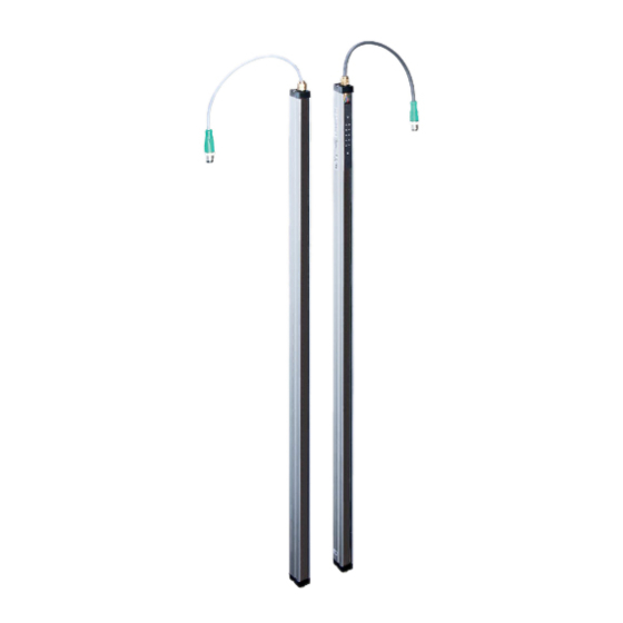
LGM Series Product Description Product Description Use and Application Features Object identification, object measurement, and positioning ■ Detecting and counting irregular objects ■ Measuring and sorting a wide variety of objects ■ Object identification ■ Description The measuring LGM light grid consists of an emitter and receiver strip. Located between the strips is the measuring detection field consisting of infrared light beams. - Page 10 LGM Series Product Description Figure 4.2 Function indicator on the receiver unit Operation indicator: indicates power-on, power-save mode, IO-Link mode aktive, or fault state Status indicator: indicates detection field status, functional reserve, or fault state Operation indicator and status indicator on the receiver...
-
Page 11: Interfaces And Connections
LGM Series Product Description Control elements Number Symbol Parameter Description Menu button Function selection OK button Function confirmation For a detailed description of the function status indicators, please see see chapter 7.1. Interfaces and Connections Use two M12 plugs for the electrical connection. The emitter unit has a cable with a 4-pin plug and the receiver unit a cable with an 8-pin plug. -
Page 12: Accessories
LGM Series Product Description Accessories An extensive range of accessories with detailed descriptions can be found in the appendix see chapter 11.7. Scope of Delivery The scope of delivery includes: Emitter unit and receiver unit ■ Quick start guide ■... -
Page 13: Installation
Check the package contents against your order and the shipping documents to ensure that all items are present and correct. Should you have any questions, direct them to Pepperl+Fuchs. Retain the original packaging in case the device is to be stored or shipped again at a later date. - Page 14 LGM Series Installation Emitter unit Detection field + 159 21.2 Detection field 137.8 Receiver unit Figure 5.1 Light Grid Dimension Drawing To mount the slim panels, use customized bore holes (d = 4.5 mm for M4 screws) or a rear, continuous groove (for flat M6 nuts in accordance with ISO 4035).
-
Page 15: Multiple Positions
LGM Series Installation Figure 5.2 Position the center point of the installation holes. Figure 5.3 Installation holes Installation Align the emitter and receiver units so they are parallel to one another and at the same height. The units must be aligned with an accuracy of approximately ± 5°. -
Page 16: Connecting The Sensor Units
LGM Series Installation Figure 5.5 Multiple assignment of two pairs of light grids Connecting the Sensor Units Caution! Electrical connection Wiring work that requires the opening and closing of electrical connections must always be per- formed with the power disconnected. - Page 17 LGM Series Installation Connection Description Test input The emitter unit features a test input with two functionalities: Pin 4 test mode • power safe mode • These functionalities can be activated by connection of the test input to either +U or 0 V.
- Page 18 LGM Series Installation Connection Description Switching output (C/Q) This connection has 2 functions. (By default, Pin 4 the switching output is active once the device is powered on; SIO mode) Switching output: This signal output is active (active with dark ON, inactive with light ON) if an object is detected or identified according to parameter settings.
-
Page 19: Grounding/Shielding
LGM Series Installation Grounding/Shielding Grounding/Shielding The system does not require grounding in standard cases. If EMC faults occur, use a grounding cable with the cable lug supplied in the scope of delivery. The grounding/shielding must always be mounted on the receiver strip. This is purely functional grounding rather than protective grounding. -
Page 20: Commissioning
LGM Series Commissioning Commissioning Final Assembly Checking the Mounting and Settings 1. Check the position of the light strips in relation to one another. The emitter strip and receiv- er strip must be aligned with one another with an accuracy of approximately ± 5°. -
Page 21: Operation
LGM Series Operation Operation Operating the Light Grid Using the Programming Interface The Receiver Strip Can Be Manually Configured and Parameterized Using the Programming Interface Standard operation in accordance with configuration and parameterized values ■ Functions of first parameterization level ■... - Page 22 LGM Series Operation The following table shows the indicators and functions of the programming interface in parame- terization mode. Number Symbol Parameter Display mode Description Menu key Repeatedly press the Menu key to select the required parameterization function OK key...
- Page 23 LGM Series Operation Number Symbol Parameter Display mode Description Signal tracking Signal tracking function selected In non-stable ambient conditions, e.g., soil- 11 8 ing and temperature changes, signal track- ing ensures that the response threshold remains constant . Reflective objects that...
- Page 24 LGM Series Operation Press the OK key to switch between permitted values or to start the selected function, e.g., to teach in parameters or to reset to default settings. Before object or suppression area teach-in, the corresponding object must be located in the detection field.
-
Page 25: Commissioning And Operating The Light Grid With Io-Link
LGM Series Operation Number Symbol Parameter Status Switching signal polarity Not inverted (dark-on) Signal tracking Inactive Table 7.3 Default settings Commissioning and Operating the Light Grid with IO-Link Commissioning with IO-Link To activate the sensor via the IO-Link, proceed with the following steps: Set the corresponding port on the IO-Link master to which the sensor is connected to IO-Link status. - Page 26 LGM Series Operation Object measurement Gap measurement NCBM CLBB NCBB CFBB Zero point reference Figure 7.2 Overview of all the Light Grid's Measurement Value Modes The measured values are based on the zero point reference in unit of millimeteres (mm). For operation with cable outlet downwards, the receiver unit can be configured via IO-Link for the zero-point reference on the cable side.
- Page 27 LGM Series Operation Abbreviation Description Total beams Gap height as the sum of all gap areas within the upper made object limits NCBM Number of con- Gap height of the largest contiguous gap area, within the secutive beams outer object limits...
-
Page 28: Description Of Individual Measurement Methods (Measured Value Modes)
LGM Series Operation Abbreviation Description GAPS Static gap identifi- An object is detected if the upper and lower limits of a gap cation match the parametrized positions of the gap field. Defined detec- Any object is detected if at least one beam is interrupted... -
Page 29: Lbb = Highest Object Position Across All Partial Objects
LGM Series Operation Figure 7.5 Function 0 = Lowest object position across all partial objects 7.2.2.2 LBB = Highest Object Position across All Partial Objects In this configuration, the distance between the first beam (at the zero point reference) and the last interrupted beam is measured. -
Page 30: Nbb = Object Height Across All Partial Objects
LGM Series Operation Figure 7.6 Function 1 = Highest object position across all partial objects 7.2.2.3 NBB = Object Height across All Partial Objects In this configuration, the distance between the first interrupted beam and the last interrupted beam is measured. The reading is in mm. -
Page 31: Tbb = Object Height As The Total Height Of All Partial Objects
LGM Series Operation Figure 7.7 Function 2 = Object height across all partial objects 7.2.2.4 TBB = Object Height as the Total Height of All Partial Objects In this configuration, the distance between the first interrupted beam and the last interrupted beam is measured. -
Page 32: Ncbb = Object Height Of The Largest Contiguous Partial Object
LGM Series Operation Figure 7.8 Function 3 = Object height as the total height of all partial objects 7.2.2.5 NCBB = Object Height of the Largest Contiguous Partial Object In this configuration, the distance between the first interrupted beam and the last interrupted beam is measured and the height of the object is output. -
Page 33: Cbb = Middle Object Position Of The Largest Contiguous Partial Object
LGM Series Operation Figure 7.9 Function 4 = Object height of largest contiguous partial object 7.2.2.6 CBB = Middle Object Position of the Largest Contiguous Partial Object In this configuration, the distance between the first interrupted beam and the last interrupted beam is measured and the middle position of the object is output. -
Page 34: Cfbb = Lowest Object Position Of The Largest Contiguous Partial Object
LGM Series Operation Figure 7.10 Function 5 = Middle object position of largest contiguous partial object 7.2.2.7 CFBB = Lowest Object Position of the Largest Contiguous Partial Object In this configuration, the distance between the first interrupted beam and the last interrupted beam is measured and the lowest position of the object is output. -
Page 35: Clbb = Highest Object Position Of The Largest Contiguous Partial Object
LGM Series Operation Figure 7.11 Function 6 = Lower object position of largest contiguous partial object 7.2.2.8 CLBB = Highest Object Position of the Largest Contiguous Partial Object In this configuration, the distance between the first interrupted beam and the last interrupted beam is measured and the highest position of the object is output. -
Page 36: Mbb = Middle Object Position Across All Partial Objects
LGM Series Operation Figure 7.12 Function 7 = Highest object position of largest contiguous partial object 7.2.2.9 MBB = Middle Object Position across All Partial Objects In this configuration, the distance between the first interrupted beam and the last interrupted beam is measured and the middle position of the object is output. -
Page 37: Fbm = Lowest Gap Position Across All Partial Objects
LGM Series Operation Figure 7.13 Function 8 = Middle object position across all partial objects 7.2.2.10 FBM = Lowest Gap Position across All Partial Objects In the following drawing, it is not the object itself that is measured. Instead, it is the gaps (holes) between the objects that are measured. -
Page 38: Lbm = Highest Gap Position Across All Partial Objects
LGM Series Operation Lowest gap position in mm Lowest gap position in mm Figure 7.14 Function 20 = Lowest gap position across all partial objects 7.2.2.11 LBM = Highest Gap Position across All Partial Objects In the following drawing, it is not the object itself that is measured. Instead, it is the gaps (holes) - Page 39 LGM Series Operation In this configuration, the distance between the first beam and the first interrupted beam of the highest partial object is measured. The reading is in mm. If there is one object only, the larger empty area is always measured. The reading is in mm.
-
Page 40: Nbm = Gap Height Within All Partial Objects
LGM Series Operation 7.2.2.12 NBM = Gap Height within All Partial Objects In the following drawing, it is not the object itself that is measured. Instead, it is the gaps (holes) between the objects that are measured. In this configuration, the distance between the first gap and the last gap is measured across all partial objects. -
Page 41: Tbm = Gap Height As The Total Of All Empty Areas
LGM Series Operation Figure 7.16 Function 22 = Gap height within all partial objects 7.2.2.13 TBM = Gap Height As the Total of All Empty Areas In the following drawing, it is not the object itself that is measured. Instead, it is the gaps (holes) -
Page 42: Ncbm = Gap Height Of The Largest Contiguous Empty Area
LGM Series Operation In this configuration, the heights of all gaps are added together. The reading is in mm. If there is one object only, the larger empty area is always measured. The reading is in mm. Figure 7.17 Function 23 = Gap height as the total of all empty areas 7.2.2.14... - Page 43 LGM Series Operation In the following drawing, it is not the object itself that is measured. Instead, it is the gaps (holes) between the objects that are measured. In this configuration, the largest contiguous empty area is output. The reading is in mm.
-
Page 44: Cbm = Middle Gap Position Of The Largest Contiguous Empty Area
LGM Series Operation Figure 7.18 Function 24 = Gap height of largest contiguous empty area 7.2.2.15 CBM = Middle Gap Position of the Largest Contiguous Empty Area In the following drawing, it is not the object itself that is measured. Instead, it is the gaps (holes) - Page 45 LGM Series Operation In this configuration, the largest contiguous area is measured and the middle position is calcu- lated. The reading is in mm. If there is one object only, the larger empty area is always measured and the middle position is output.
-
Page 46: Trn = Number Of Transitions From Interrupted To Vacant Beams
LGM Series Operation 7.2.2.16 TRN = Number of Transitions from Interrupted to Vacant Beams In this configuration, the number of transitions from interrupted to vacant beams and vice-versa are output. If the number is odd, one of the two synchronous beams has been interrupted by an object. - Page 47 LGM Series Operation TRN = 2 TRN = 1 TRN = 6 TRN = 7 Figure 7.20 Function 30 = Number of transitions from detected to nondetected beams...
-
Page 48: Io-Link Programming
FrameCapability Supports SPDU (0x01) 0x04 RevisionID IO-Link 1.0 (0x10) 0x05 ProcessDataIn 16-bit data capacity, supports SIO (0x50) ID Parameters Address Name Value Description 0x07 VendorID1 (MSB) Hexadecimal: All Pepperl+Fuchs IO-Link devices 0x0001 have the same vendor ID 0x08 VendorID2 (LSB) Decimal: 1... -
Page 49: Process Data
ID in the specified 0x0A DeviceID2 00720 range Decimal: 0x0B DeviceID3 (LSB) 1050369 ... 1050 Device ID for Devices in the LGM Series Device ID LGM devices 0x100701 (1050369) LGMnn-100 0x100702 (1050370) LGMnn-200 0x100703 (1050371) LGMnn-300 0x10071F (1050399) -
Page 50: Io-Link Parameters
Constant www.pepperl- fuchs.com/io-link This parameter contains a link to the Pepperl+Fuchs IO-Link website with additional information on IO-Link devices and tools, and the latest software downloads. The value is fixed, has an invariable text length, and cannot be modified. Product Name... - Page 51 LGM Series IO-Link Programming Product ID Date Index hex (dec) index type/Length Type Default value 0x13 (19) char[11] Constant Example: 251331-0034 This parameter contains the order number/item number of the device specific to Pep- perl+Fuchs The value is fixed, has an invariable text length, and cannot be modified.
-
Page 52: Parameterization And Configuration
LGM Series IO-Link Programming This parameter can be used to further identify the device by means of a numerical value. This value may be a plant ID. The value can be altered within the permissible value range and is saved permanently in the device. - Page 53 LGM Series IO-Link Programming The value can be altered within the permissible value range (see table) and is saved perma- nently in the device. Permissible value range Value Abbreviation Function Description and remarks First beam Lowest object position across all partial...
- Page 54 LGM Series IO-Link Programming Date Index hex type/Len Value Default (dec) Subindex R/W Type range Unit value 0x40 (64) 3 Uinteger Remanent 0 ... <max <max- Length> Length> Gap range - position 2 0x40 (64) 4 Uinteger Remanent 0 ... <max <max-...
- Page 55 LGM Series IO-Link Programming Date Index hex type/Len Value Default (dec) Subindex R/W Type range Unit value Tolerance factor 0x49 (73) 3 Uinteger Remanent 0 ... 5 These parameters are used to configure the operating values for suppression area 1.
- Page 56 LGM Series IO-Link Programming Measurement Mode Value Range Value Function Description and remarks Single beam scanning The device functions with basic position reso- lution Three-way beam crossover The device functions with three times as much position resolution Measuring Type Configuration - Detection Direction...
- Page 57 LGM Series IO-Link Programming Switching Signal Configuration - Switching Signal Polarity Index Date Subin- type/Le Default (dec) ngth Type Value range Unit value 0x70 Uinte- Remanent 0 ... 1 (112) ger 8 Switching Signal Configuration - Switching Signal Delay Index...
- Page 58 LGM Series IO-Link Programming Teach-in - Switching Signal Date Index type/ Defau Sub- Lengt Value (dec) index R/W Type range Unit value 0x69 Uinte- Vola- 0 ... 2 (105) ger 16 tile Sensor Configuration - Response Threshold Index Date Subin-...
-
Page 59: Monitoring
LGM Series IO-Link Programming Event Configuration - Warning: Test Mode Active Index Date Subin- type/Le Default (dec) ngth Type Value range Unit value 0x74 Uinte- Remanent 0bXXXX 1XXX (116) ger 8 Event Configuration - Warning: Excess Temperature Index Date Subin-... - Page 60 LGM Series IO-Link Programming Output Mode Control - Q Polarity (BD1) Permis- sible Index Index Subin- Date value Default type/Length Memory range setting 0x70 uint[8] Remanent 0 ... 1 Output of switching state at output Q 0 = dark ON, 1 = light ON...
-
Page 61: Diagnostic Function
LGM Series IO-Link Programming Specification of measured object height. This value is composed of the highest measured object position minus the lowest object position. 8.4.4 Diagnostic Function In the event of a fault, the sensor transmits a corresponding fault message with an error code via IO-Link to the connected control unit for each event. - Page 62 LGM Series IO-Link Programming OVT Operating Hours Index Index Subin- Date Permissible type/Length Memory value range 0xE2 uint[32] Remanent 0 ... 4294967295 OVT Exceeded Counter Index Index Subin- Date Permissible type/Length Memory value range 0xE2 uint[16] Remanent 0 ... 65535 Number of instances of excess temperature: Specification of the number of instances of excess temperature that have occurred.
- Page 63 LGM Series IO-Link Programming Specification of measured object height. This value is composed of the highest measured object position minus the lowest object position. Device Characteristics - Number of Beams (Physically) Index Index Subin- Date Permissible type/Length Memory value range...
-
Page 64: Events
LGM Series IO-Link Programming Specification of IO-Link version ID. This is a read-only field. 8.4.5 Events The device sends events via the IO-Link interface depending on the parameterization. These are available only in communicative operation. The following events are possible see chapter 11.1.5:... -
Page 65: Maintenance And Repair
If it appears that safe operation of the sensor system is no longer possible, it must be taken out of operation and secured against inadvertent use. Always send both parts of the device (transmitter and receiver strip) to Pepperl+Fuchs together for repair. -
Page 66: Troubleshooting
LGM Series Troubleshooting Troubleshooting 10.1 Troubleshooting Before requesting field service, check that the following actions have been taken: The plant has been tested according to the following checklists. ■ Telephone assistance obtained from the Service Center to isolate the problem. - Page 67 LGM Series Troubleshooting Press the Menu button repeatedly until the "H3" icon starts flashing. If you now press the OK button , the light grid will be restored to its factory settings..
-
Page 68: Appendix
LGM Series Appendix Appendix 11.1 Process Data Structure The process data is transmitted as a 16-bit word. See chapter 8.3 11.1.1 IO-Link Communication and ID Parameters Address hex (dec) Name Type Data type Attributes Value Comment Communication parameter 0x00 (0) -
Page 69: Io-Link Predefined Parameters - Standard Index
LGM Series Appendix 11.1.2 IO-Link Predefined Parameters - Standard Index Index hex (dec) Name Type Data type Attributes Value System style 0x02 (2) System com- uint8 Static mand 0x0D (13) Profile ID record Static 0x0E (14) PD input record Static... -
Page 70: Io-Link Device Parameters
LGM Series Appendix 11.1.3 IO-Link Device Parameters Index hex (dec) Sub Name Type Data type Value Default Unit Comment Operation parameters 0x40 (64) Switch- record ing signal detection range - Q (BD1) Lowest uint16 0 ... 3200 mm Depending on... - Page 71 LGM Series Appendix Index hex (dec) Sub Name Type Data type Value Default Unit Comment 0x49 (73) Blanking record range 1 - FBR1 Lowest uint16 0 ... 3200 position range - Highest uint16 0 ... 3200 position range - FBR1 tol- uint8 0 ...
- Page 72 LGM Series Appendix Index hex (dec) Sub Name Type Data type Value Default Unit Comment 0x51 (81) hysteresis R/W uint8 0 - small 1 - medium 2 - large 0x55 (85) Stability uint8 0 - low level control threshold threshold...
- Page 73 LGM Series Appendix Index hex (dec) Sub Name Type Data type Value Default Unit Comment 0x61 (97) Measure- uint8 0 - normal ment scan/single beam mode overscan/crossin g beam 0x62 (98) Evalua- uint8 0 - normal tion mode 1 - inverse...
- Page 74 LGM Series Appendix Index hex (dec) Sub Name Type Data type Value Default Unit Comment 0x69 (105) Teach sta- uint16 LSB: Status 0bXXXX 0000 - flags are no objects Teach- read-only 0bXXXX XXX1 - Q taught 0bXXXX XX1X - blanking range...
- Page 75 LGM Series Appendix Index hex (dec) Sub Name Type Data type Value Default Unit Comment 0x73 (115) Local uint8 0xb0000 0000 - Actual setting of control no button local control ele- status pressed ments 0xb0000 00X1 - function select button pressed...
-
Page 76: Error Codes
LGM Series Appendix Index hex (dec) Sub Name Type Data type Value Default Unit Comment 0xE2 (226) Operat- record ing moni- OVT Oper- uint32 0 ... 4294967295 Operating hours ating with exceeded Hours operation condi- tions uint16 0 ... 65535... -
Page 77: Result Data
LGM Series Appendix 11.1.5 Result Data The sensor is capable of transmitting events that occur: Instanc Event Event Event Type Mode qualifier code Description Parameter error Error Single shot 0x74 0x6320 Parameter modi- Message Single shot 0x54 0x6350 fied Hardware fault... - Page 78 LGM Series Appendix Indicators/operating means Operation indicator LED green: constantly on - power-on double pulse flashing (0.8 Hz) - undervoltage flashing (4 Hz) - short circuit flashing with short interruptions (1 Hz) - IO-Link mode Status indicator Emitter: LED yellow...
-
Page 79: Type Code
30 m 11.3 Type code Automation light grids from the LGM Series are designated a code according to the fol- lowing format: LGMxx - yyyy - IO/Options xx thereby denotes the resolution, yyyy the height of the detection field, IO the integrated IO interface, and Options further options. -
Page 80: Switch-On Delay And Number Of Beams
LGM Series Appendix Resolution [mm] Detection field [mm] IO-Link interface Options 100, 300, … 3200 /110/115b 300, 600, … 3000 /110/115b Clarification of Options /110 Push-pull switching output 0.1 A, short-circuit proof, reverse polarity pro- tected (series) /115b M12 plug-in connector with 200 mm connection cable (pigtail, series) 11.4... - Page 81 LGM Series Appendix Switch-on delay [ms] C/Q output with object parameterization and Detection Number of C/Q output without updated measured Versions field [mm] beams object parameterization value Type Max. Type Max. LGM17-200 200 LGM17-300 300 LGM17-400 400 LGM17-500 500 LGM17-600 600...
- Page 82 LGM Series Appendix Switch-on delay [ms] C/Q output with object parameterization and Detection Number of C/Q output without updated measured Versions field [mm] beams object parameterization value Type Max. Type Max. LGM17- 2800 2800 LGM17- 2900 2900 LGM17- 3000 3000...
- Page 83 LGM Series Appendix Switch-on delay [ms] C/Q output with object parameterization and Detection Number of C/Q output without updated measured Versions field [mm] beams object parameterization value Type Max. Type Max. LGM25- 2300 2300 LGM25- 2400 2400 LGM25- 2500 2500...
-
Page 84: Switching Frequencies And Time Delay Before Availability
LGM Series Appendix 11.5 Switching Frequencies and Time Delay before Availability Maximum time delay before Maximum switching fre- availability t Versions quency [Hz] LGM8-100 LGM8-300 LGM8-600 LGM8-900 LGM8-1200 LGM8-1500 LGM8-1800 LGM8-2100 LGM17-100 LGM17-300 LGM17-600 LGM17-900 LGM17-1200 LGM17-1500 LGM17-1800 LGM17-2100 LGM17-2400... -
Page 85: Profile Length And Weight
LGM Series Appendix Maximum time delay before Maximum switching fre- availability t Versions quency [Hz] LGM50-1200 LGM50-1500 LGM50-1800 LGM50-2100 LGM50-2400 LGM50-2700 LGM50-3000 Table 11.2 Maximum switching frequencies and maximum time delay before availability 11.6 Profile length and weight Profile length and weight... -
Page 86: Accessories
LGM Series Appendix Overall length of the trans- Weight of transmitter / Detection field [mm] mitter / receiver strip [mm] receiver strip [g] 2800 2960 1550 2900 3060 1600 3000 3160 1650 3100 3260 1700 3200 3360 1750 Table 11.3 Profile length and weight per strip 11.7... -
Page 87: Mounting Aid Omh-Slct-01
LGM Series Appendix Designation Illustration Description OMH-SLCT-05 Mounting bracket AA SLCT-01 Profile alignment tool Table 11.4 Accessories list 11.7.1.1 Mounting Aid OMH-SLCT-01 Model number: OMH-SLCT-01 The emitters/receivers can be secured using mounting aids that grip the dovetail guide. There are dovetail guides on three sides of the profile. When mounting and aligning the unit, avoid subjecting the profile to mechanical tension. -
Page 88: Alignment Aid
LGM Series Appendix OMH-LGS-01 OMH-SLCT-01 ø 4.3 OMH-SLCT-01 OMH-LGS-01 42.8 Figure 11.1 Dimensional drawing and fitting mounting accessory OMH-LGS-01 11.7.1.3 Alignment aid Order code: AA-SLCT-01 The transmitter and receiver should always be aligned at the same height in parallel to one another. -
Page 89: Connecting Cables
LGM Series Appendix ø 21 24.5 21.5 23.4 11.1 ø 5.5 Figure 11.2 Dimensional drawing and assembly of the alignment AA-SLCT-01 11.7.2 Connecting Cables Various 4-pin and 8-pin connecting cables are available in different cable lengths. Connecting cables for automation light grids... - Page 90 Pepperl+Fuchs Quality Download our latest policy here: www.pepperl-fuchs.com/quality www.pepperl-fuchs.com © Pepperl+Fuchs · Subject to modifications Printed in Germany / DOCT-2871D...
Need help?
Do you have a question about the LGM Series and is the answer not in the manual?
Questions and answers